Power
Operated and Colour Light Signals
Power Operated Mechanical Signals
Signalling
using electrical systems appeared on the Lancaster & Preston
Railway as far back as 1849 but the equipment available at that time
was simply not reliable enough for the job. Power operated points and
semaphore signals started to appear in about 1900. There were various
systems used but the most common point operating system was probably the electro-hydraulic
type. In these the signalman operated a switch which caused a
hydraulic pump at the point to move the blades across.
On the subject of power operated semaphore signals John Webb was able to advise that-
There were many schemes in the 20th century (Crewe, Hull, LSWR in the Southampton area, Southern Railway after 1923, East coast mainline around Thirsk etc) where some form of power signalling was in use. They included electrical solenoids, electro-pnumatic, electric motor etc. I warmly recommend "Two Centuries of Signalling History" by Geoffery Kitchenside and Alan Williams, published by OPC in 1998 for a quite detailed and well-illustrated tour of signalling developments.
The
first power operated signal box in Britain was at Bishopsgate in
London, on the Great Eastern Railway, which opened in 1899 (the first
in the world was probably the Westinghouse system installed on the
Philadelphia & Reading Railroad in America in 1884). The
Lancashire & Yorkshire Railway was one of the pioneers of power
operation and they also developed double-acting three position levers
for power operated signal boxes. In the centre position everything
was at its normal orientation, pulling the lever set a series of
points for one route, pushing it set them the other way. The
combination of power operation and three-position switches resulted
in a dramatic reduction in the number of levers required for a given
signal box but the system was not widely adopted.
Power
operation also reduced the number of signal boxes required as it
allowed the box to operate signals at much greater distances. The
re-signalling of a station at Wigan in 1939 with colour light signals
and power operated points reduced the signals boxes required from
twelve to three.
Electric Coloured Light
Signals
Electric coloured light signals were
experimented with as early as 1913 but it was the 1920's before
they became widespread. The lamps used need to have six or seven
thousand candle power to be clearly visible in daylight and making
lamps which were sufficiently powerful and also reliable was a major
challenge for the existing technology.
Incidentally as it is
railway terminology to refer to a signal as 'on' when it is at stop
or red and 'off' when it is at proceed, i.e. yellow or green
confusion is avoided by not using on and off to refer to individual
lamps they would be referred to as 'lit' and 'out'
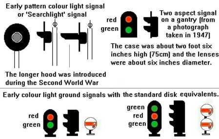
Early
colour light signal designs were many and varied, the light units
were usually mounted on a post and pointing along the track. Mounted
on the front of the light housing was a large back-plate painted
black to make the signal more visible. Building on trusted technology
the signals had a single lamp with a reflector behind and a
mechanical spectacle plate carrying coloured glass filters mounted in
front of the lamp, all inside the casing. The spectacle plate was
operated by polarized relays, switching between red and either green
(for a home signal) or yellow (for a distant signal). This single
glass design was widely used and remained popular on Eastern Region
of BR for many years. They are still in widespread use around the
world, notably in the USA.
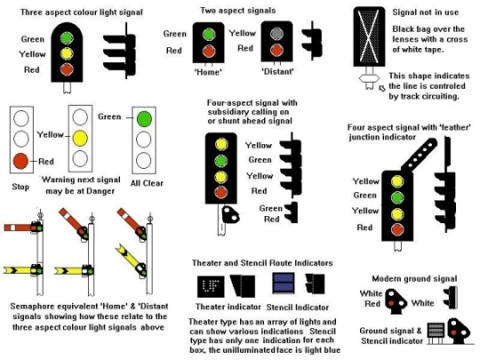
More recent designs have favoured
the use of separate lamps and lenses for the different colours. The
simplest type is the two aspect signal which has two separate lights,
one above the other. These can be used to replace simple semaphore
signals with red and green lights for a 'home' signal and
red and yellow for a 'distant'. The first serious use of
colour light signals was on the Liverpool Overhead Railway where over
fifty two-aspect (that means two lens) colour light signals were
installed in 1921. The three aspect colour light signal has three
lights, red at the bottom then yellow and green at the top. The three
aspect signal serves the same function as the combined home and
distant semaphore type signal as shown in the sketch below.
Fig___
Early colour light signals
Note you will often see colour light signals with
long 'hoods' on the front, these were introduced in the
Second World War as part of the black-out precautions to prevent
enemy bombers using the signals to find their way to the target. Once
fitted they remained in place until major maintenance was required
and some long hoods lasted into the 1970's.
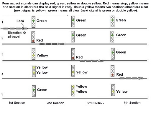
The most
common design on busy lines is the four-aspect signal which has four
separate lamps mounted one above the other. The four aspect has a
yellow at the top, then a green, another yellow and a red at the
bottom. Red means stop, green means all-clear, yellow means the next
signal is red and double yellow means the next signal is yellow. The
four aspect signal first appeared on the Southern Railway commuter
lines in the London area in 1923 and its application is probably best
explained in the form of a drawing.
Fig___ Four aspect
colour light signalling
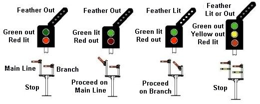
Junction signals have a rack of five white lamps inclined
at 45 degrees in the direction of the diverging line. These lights
are called 'feathers' by railwaymen and several sets of
'feathers' can be added at thirty degree angles where more
than one diverging route is approached. Adding the 'feather'
to a simple two aspect signal means it can replace a bracket signal
with two arms. When the signal shows a red light it means 'Stop',
a green light with the feather switched off means 'Proceed on
the main line', a green light with the white feather illuminated
means 'Proceed on the branch line'. A three aspect signal
with a feather can replace four semaphore arms on a bracket signal,
in this case a yellow light with no feather means 'Proceed on
the main line with caution' and a yellow with the feather
illuminated means 'Proceed on the branch line with caution'.
It is quite usual to see feather added to four aspect signals,
particularly at junctions on busy suburban or main lines.
Fig___
Junction signal with semaphore equivalent
There are two different variations on the old mechanical
route indicating box. The stencil type has a fixed cut-out with a
light behind it, these boxes are typically twelve inches wide by nine
inches high by about six inches deep and you may see two or even
three of these small boxes one above the other. They are usually
associated with ground signals, allowing one signal to control a
number of sidings. The second design, known by railwaymen as
'theatre' indicators, uses a box with an array of lights
which can be switched to show letters and numbers as required, these
tend to be quite large, typically eighteen inches square by six
inches thick. At Stockport station, which is on a four-track main
line, the platform starter signals have this latter type. The lights
are switched to show F or S for Fast and Slow lines. Originally the
theatre indicators used a matrix of lamps, usually 5 x 7, but more
recently fibre optics have been used, allowing a single lamp to be
used for each indication.
The modern colour light ground
signal has three lights, two white and a red arranged as shown in the
sketch, the lower white light is always on. Two white lights means
'all clear', one white and a red means 'stop'. To
avoid having multiple electric ground signals it is common practice
to add a stencil route indicator allowing one signal to cover two or
three routes.
The old 'shunt ahead' and 'calling
on' signals described above have been replaced with small units
resembling modern electric colour-light ground signals but with only
two lights, both white. These units are mounted on the post or gantry
immediately below the main signal unit and often have hoods on the
lenses to make them more visible against the sky.
Fig___
Sketches of modern signals
Models
of colour light signals are available from a number of sources, most
now use LED's but I believe some still use small 'grain of wheat
lamps'. These lamps are less reliable than LED's, running them on
reduced voltage prologues their life considerably but changing the
bulbs when they fail calls for a steady hand (and a removable
signal!). Both these ranges offer two, three and four aspect signals
suitable for any period from the later 1920's to the present
day.
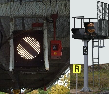
The colour light equivalent of the old banner repeater
signal is a circular housing with a matrix of white lights. These are
switched to show the position of the associated signal. John Sullivan
was kind enough to supply me with a photograph of one of these units
in use in 2003, the picture on the left shows the signal displaying the all clear
indication. The photo on the right is a free standing banner repeater with an associated stencil display in use at Stockport in 2007. This signal is located at the end of a platform road close by an overbridge where the main line curves slightly, so the actual signal cannot be seen, it is displaying the 'danger' aspect.
Fig___ Colour light banner repeater signal
A photo of the older mechanical type is included in the section on Signals -
Mechanical Types & Fog Signals.
^
Go to top of page
International Good Guys ~ Gazing into the middle distance since 1971 ~ Site maintained by

All material Copyright © Mike Smith 2003 unless otherwise credited