Communications, & Traffic Control
This section details the methods of communication used by the
railways and covers the systems used to control the flow of traffic and monitor
rolling stock use.
There is an associated page in this section covering the use
of single stroke bells by signal boxes and the use of locomotive head codes
(Communications, Control and Signalling - Bell Codes & Locomotive Head
Codes).
Communications &
Control
In 1835 an American called Samuel Morse developed the
famous Morse Code, this was devised to allow messages to be written down on a
moving strip of paper by use of an electromagnet which pulls a pencil into
contact with the paper. This is 'writing at a distance' hence the
generic term of 'telegraphy'. The code consists of short and long
lines (called dots and dashes or dits and dahs) arranged in sequence for each
letter of the alphabet and for the numbers 0-9, for example A is one short
followed by one long, usually expressed at 'dit dah'. In America the
telegraphist working on the railways proved able to understand the clicks
produced by the electromagnet and the moving tape was dispensed with. The
clicking contacts were fine for a single man alone in a room but where more
than one operator was working a buzzer or beeper and a set of headphones was
added to the equipment.
In 1839 Wheatstone and Cooke introduced the
world's first telegraph service, employing Morse Code, between the Great
Western Railway stations at Paddington and West Drayton. The GWR, having
pioneered two different telegraph systems then lost interest and did not fully
take up the telegraph until the 1850's. Other companies however saw the
potential for the system and the link between the railway and telegraphy
continued as most of the telegraph lines were installed alongside the railway
lines.
For many railway company internal communications it was not
necessary to use anything as sophisticated as Morse code, for example signal
boxes only needed to send a very limited range of signals to each other. Signal
boxes used simple single stroke bells in which a coil of wire was mounted
inside the bell, inside the coil was a brass rod and underneath was an iron
plate. When power was applied the iron plate was pulled sharply up against the
coil, flipping the brass rod upwards to strike the shell of the bell, giving a
single 'ting'.
Signalmen, usually called 'bobbies', had
standard codes such as three pause three pause two. The man in the receiving
box then sent the same message back down the line to confirm he had heard it
correctly. Signalmen had to learn not only these codes but also to distinguish
the bells of other boxes by the sound they made, at a major junction there
might be twenty different bells connected to outlying signal boxes, all ringing
frequently. By the end of the nineteenth century most signal boxes were
equipped with single-stroke telegraph equipment and other simple electrical
instruments which indicated the position of signals controlled by adjacent
boxes and the like.
The bobby with a train to send gives one bell to
attract the attention of the next box on the line. If that box replies by
sending one bell the first bobby sends the code for the type of train he or she
wishes to send, the second box sends this same code back to accept the train.
As the train passes the first box the bobby sends 2 bells (train entering
section) and the second bobby sends this back to confirm he heard it. When the
train clears the second box the signalman there sends 2-1 which means
'train out of section' and the first box sends this back as an
acknowledgment.
There had to be a degree of standardisation in bell
signals where two companies lines met and the signal box on one line needed to
communicate with the box on the other line. There were however a number of
variations specific to the individual companies and it was only in 1960 was a
truly national set of codes established (and even then there were a few extra
codes used where special circumstances existed. See section on Bell Codes and
Loco Head Codes for details).
With the introduction of 'block working' (described below) there came a need for electrical signalling system that would allow one signal box to indicate to another how his signals and points were set. The instruments used were called 'block instruments' and featured a needle that could be electrically pulled to one side or the other to indicate 'clear' or 'blocked'.
The railways adopted the telephone for some communications duties but the single stroke bells and electrical 'block' instruments remained standard equipment into the early twenty first century.
Operational communications & telegraphic codes
The railways had to keep track of large numbers of individual
vehicles, arranging for these to be placed where required to ease traffic flow
and the use of telegraph systems made this work considerably easier. Using the
telegraph messages could be sent in the Morse code, describing the make up of a
train being sent down the line or requesting a special type of vehicle. Simple
bell codes were impractical for this work so Morse code was used.
Messages sent by Morse code are sent letter by letter, when used with a
buzzer or 'clicker' messages in Morse code are easier to write down and less
liable to mistakes than if a telephone were used, but sending and writing out
the message takes time. This resulted in the development of the 'telegraphic
codes', these were books listing commonly used words and phrases each with a
single code word. Sending the code word saved time and effort and telegraphic
codes sent in Morse remained in wide use all over the world until the
teleprinter was developed in the 1940's. These telegraphic codes were not
'secret' as such, the Post Office Telegraphy Act 1884 specifically prohibits
the use of 'secret language' in any messages sent via the Post Office system
and this was applied to the railways private telegraph systems as well.
Telegraphic code books were compiled and sold commercially to shipping
companies, railways and other large commercial concerns. The railway code books
contained single words for describing all the standard wagon types and also of
frequently used sentences, such as 'Please arrange for a horse box to be
included in the pick up goods train on . . .'.
All the railway companies
used telegraphic codes, but of course they each had their own. There was a
degree of standardisation but the London North Western Railway, the Caledonian
Railway and some others used very different systems to everyone else. It was
only in 1943 that a standard country-wide railway telegraphic code was
established and it took several years for this unified code to be
applied.
The telegraphic code word for a vehicle was sometimes written
on the body side or chassis of a wagon or van but this was not by any means
universal and was more likely on a non-standard or specialised vehicle than on
a run of the mill five plank open or ventilated van. Sometimes the marking used
was different from the telegraphic code, as an example the GWR 4-plank long
wheel base open 'tube wagon', coded OPEN C, had the code written on the lower
left of the body, whereas the ventilated van (available from Peco) which was
coded MINK had the word 'VENTILATED' on the lower left of the body side. Where
the details of such markings are known, and relevant to specific models, they
have been included in the text. The reader is recommended to look for
photographs of the original rather than models on other's layouts, even the RTR
models are often wrongly marked.
The wartime standard telegraphic codes
remained in use under British Railways, with new ones added when required, up
to the introduction of the TOPS computerised system in 1974. TOPS is more fully
discussed under Control below, a list of TOPS codes is included in Appendix
1.
Telephones, Teleprinters and Facsimile
Alexander Graham Bell, a Scottish scientist, was experimenting with
sending different sounds down a single pair of wires to allow multiple Morse
code calls via a single line when he found he had accidentally invented the
telephone. Practical telephones appeared on the market in the 1870's and by the
early 1880's they had been adopted by the railways (public telephone boxes
appeared in the mid 1880's).
The railways made some use of teleprinters
(usually called 'telex'), but usually only between major centres. Telex consist
of two electric typewriters linked together by a telephone type connection
(telex did not use the normal telephone lines but had a separate network).
Facsimile (or 'fax') has been little used operationally by the railways, it
sends text messages at about the same speed as telex but the print out is often
less readable and the railways had little operational need for the simple
drawings facsimile can reliably transmit.
By the time fax had become a
practical proposition computers were in place and the GPO telephone people had
invented the 'modem' allowing computers to be connected together via the
telephone system. This was intended as a replacement and improvement for telex and the original specification allowed fifty characters per second to be transmitted, a major improvement on the older teleprinter. Telex was well established however and remained the workhorse of business communications into the 1990's. Meanwhile British Railways had purchased an American computer system for controlling
traffic movements called TOPS (Total Operations Processing System, discussed in
more details below). One big advantage was that the central TOPS computers
could be directly accessed by customers tracking a specific shipment through
the system. Getting the customers computer to check with the TOPS computer is a
better option than faxing poor quality copies of bits of paper so the customer
could hand type the data into their machine.
The transmission speeds were slow, big business used specially laid high speed data cables for their traffic but modem technology remained a specialised niche market until the 1980's. Then the growth of home computer ownership provided a mass market for improved equipment able to use the conventional telephone system. Telephone systems used something called 'multiplexing' to allow more than one telephone call to be carried on a single pair of wires, the introduction of digital technology greatly increased the carrying capacity of the line and by the late 1980's, with the telephone network was itself switching to fully digital technology. By the later 1980's computer data could be routinely transmitted many
times faster and cheaper than standard fax. With the opening of the Internet to private subscribers in the early 1990's the mass market funded the development of ever more sophisticated equipment and easy to use programs were produced to allow the sending of messages by 'e-mail'. This has now largely replaced the fax machine as the principle medium for sending documents between offices and has been widely adopted by the railways for internal communications.
Radio
Systems
Telegraph, telephone and e-mail require wires to be run between the subscribers and so cannot be used to communicate with trains on the move through the system. If a train was stopped unexpectedly by a signal the driver had to dismount to use a telephone link to the signal box. The military had found radio to be a vital communications medium and they funded the development of improved radio communication systems following the second world war. Using radio links between the locomotive and track
authorities such as signal boxes and stations is a relatively new idea. In the
1970's an analogue network was devised called the National Radio Network (NRN).
This was up and running by the mid 1980's but the limitations of the system,
principally the limited traffic capacity of the analogue system, reduced its
usefulness. A revised system called Cab Secure Radio (CSR) was developed in the
later 1980's which allowed direct communication between the driver and the
signalling staff but this was still based on analogue signalling methods and
had limited traffic capacity. By the early 1990's the cost of the old analogue
cellular phone service was greater than that for a digital system and Railtrack
worked with Racal (who handled all the railway communications services up to
1997) on a fully digital service called Digital Advanced Radio for Trains. This
system would allow data to be passed to drivers using small screens in the cab
and also supported direct voice communications between the train and the
track authorities. In the event the upheavals in the industry meant that DART was never implemented and by the end of the 1990's interest was increasingly focused on finding a cheaper alternative. In the meantime train crews began using standard civilian mobile telephones to contact the controllers via the normal telephone system. This is less than ideal, I was on a train involved in an incident one evening and it took the staff a good fifteen minutes to establish communications with the signallers. With the closure of the manned signal boxes there is no longer a human checking that a train is clear of a section and increasingly the railways are relying on track circuits to report back the position of the train (track circuits use the train axle to make an electrical connection between the rails, causing a signal to be passed back to the signallers).
Traffic Control
From the start of railways men were used to regulate the traffic
flow, the staff doing this were employed as 'policemen', this being a new 'high
tech' term as the Metropolitan Police had been established in 1829, a year
before the opening of the Liverpool and Manchester line. Uniforms for railway
staff were introduced by the Liverpool & Manchester Railway in the 1830's
and the railway 'policemen' used the same uniform as the Metropolitan police
force; a belted single breasted tunic and top hat. The Metropolitan Police were
set up by Robert Peel and were soon being called 'Bobbie's Men'
or simply 'bobbies' and this term was adopted for the railway
'policemen' by railway staff, a nickname which stuck even after the change of
the job title to signalman.
In the early days the engine driver carried
a great deal of responsibility for safety. Before starting he had to check that
the loads were secure and sheeted over with tarpaulin and when on the line he
was to ensure he maintained a distance of about 600 yards from the train in
front, more where the track was on an incline. Where things became difficult,
such as when the 'wrong line' had to be used, the engine driver obeyed the
instructions of the bobbies stationed by the line side.
Time Tables
The increase in the connecting of lines
and the arrival of through services in the late 1830's prompted the compilation
of the first proper time tables, which became the backbone of railway
operations. One side effect of the time table was the standardisation of time
throughout the country, prior to this each town used local time, the time that
would be shown on a sun dial. The standard was taken as the local time at the
Greenwich Naval Observatory and was known as Greenwich Mean Time or GMT for
short. Norwich local time is about five minutes ahead of GMT, Oxford is about
five minutes behind and Bristol is some ten minutes behind. Obviously everyone
had to keep the same time if timetables were to make sense, on the railways
staff were issued with pocket watches, stations were equipped with clocks, and
'time signals' were sent out each day by the electric telegraph apparatus so
that all the clocks and watches could be synchronised. The new national
standard time was generally known as 'Railway Time' up to about the 1860's
after which the term GMT became increasingly common.
The Interval System
As train speeds increased in the
1830's it had become dangerous to rely on the eyesight of the locomotive driver
but with a time table to work to trains could be sent out with a fair degree of
surety that the line ahead was clear.
This idea was developed into the
'interval' system of working in which if one train reached a signal man too
soon after an earlier train it was stopped or told to slow down. Providing
speeds were maintained and no trains actually broke down this system worked
quite well and was adopted by all the railway companies at the time. The
railway companies published official lists of intervals for different types of
train and locomotives were fitted with brackets on the front to carry lamps
which indicated the type of train they were pulling and hence the official
speed at which they would be travelling. These lamps on the front of the
locomotive were called the 'Headcode' (see section on Bell Codes and Loco Head
Codes).
The 'bobby' had to decide, based on the 'headcode', if the last
train was far enough ahead for safety and indicate this to an approaching train
crew. The intervals between trains were based on the average speed of the
various kinds of train and signal men and crossing keepers along the line used
signals of various kinds to advise the train crew how long it had been since
the last train passed by and what kind of train it was. This method of working
was generally abandoned in favour of the 'block system' described below,
however the block system relied on electrical communication between signal
boxes and interlocking of mechanical signalling which took time to
evolve.
Block Working
Up to the mid
1880's stopping a train was a major exercise, not to be undertaken lightly, so
the railway often had right of way and level crossing gates were normally
closed across the road, leaving the railway open. Similarly signals were
normally left at the 'all clear' position unless the signalman decided
otherwise. After 1889 all level crossings had to be manned and after 1890, with
improvements in braking systems and the widespread introduction of electric
telegraph equipment, signals were normally set to Danger and level crossing
gates were normally kept closed across the railway. Level crossings are
discussed in more detail in the section on signals.
In 1844 the Yarmouth
& Norwich Railway had introduced the so called 'block' system in which the
track was divided up into sections, with a signal box at each end connected by
electric signalling systems of the bell type (this was one of the first uses
for electrical signalling systems). Only one train was allowed on the section
of line between any two signal boxes, the idea being that this would prevent
trains running into the rear of the train ahead and on single lines it would
prevent collisions.
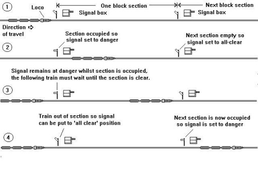
As a train approached a box the signal man would
'offer' the train to the next box up the line using his single stroke bell
apparatus to tell him what kind of train it was. If the previous train was
clear of the section the distant signalman would send the acceptance code. When
the train passed into a section the first signalman would set the local 'home'
signal to danger to prevent any train following it up the line, a 'distant'
signal farther up the line might also be set to warn oncoming traffic
(information on home and distant signals will be found in the section on
signals).
The signalman would watch the train pass and check that there
was a lamp on the last wagon (this meant no wagons had been left behind in the
last section). Then he would send a message to the next box telling them the
train had passed him in their direction and another message to the signal box
on the other side telling him that the train has passed and no wagons had been
left in the section. Only when the next signal box on the line sent a message
saying that the train had passed out of the section and no wagons were missing
from the end did the signalman change his signals to 'all clear'. This is
called 'block signalling' because the signalman 'blocked' the section by
setting his signals to Danger. Following an accident in Ireland in 1889 block
working became mandatory and by the time of the First World War the entire
British railway system was using this block system. With the introduction of
electrical interlocking, enabling a signalman in one box to prevent the
signalman in the next box from changing a signal to 'all clear', block working
became very safe and effective.
Fig___ Principles of the
Block System
Single Line Working
Single
line, on which trains travelled in both directions on the same track, presented
additional problems. One simple solution was to only allow a single locomotive
to be operating on the single line at any one time, which in many cases was not
a problem as single lines tended to be confined to the more remote areas where
traffic was light.
Where more than one locomotive was likely to operate
the first solution adopted was to have a man authorised to accompany trains and
only when he was on board could the train proceed. Someone realised that the
man was not required as long as his badge of office was used and in 1853 the
LNWR introduced a system involving a staff or baton, which was handed to the
train driver as he entered the section of track, only a driver in possession of
the staff could proceed.
This system had its complications of
course, with only one token once a train had passed in one direction the
signalman had to wait for another train to return the token before he could
allow any further trains to pass. This was often not a problem as many of
branch lines were unlikely to see more than one train on the line at a
time.
With the development of electric communication and signalling the
staff system was developed to incorporate an electrical locking mechanism for
which the 'staff' was the key. Over time a range of alternative devices were
developed using smaller 'keys', 'tablets' or 'tokens'. These were not so easy
to exchange so they were placed in a sturdy leather pouch fitted with an
eighteen inch diameter hoop to make it easier for signalmen or train crew to
catch them with their arm as they passed.
The electric token system
invented by Edward Tyler in 1878 revolutionised single line signalling. The
basic idea was to have a number of tokens, sometimes called a 'tablet', which
fitted into receivers in the signal boxes at each end of a section. Only when
all the tokens were in place was the circuit completed and the signals released
but they could be divided between the signal boxes in any order. In this way
once a train was in the section, carrying a token, the signals could not be
changed at either end of the section, nor could the block signalling
instruments be altered. The token was passed to the train driver, so he knew he
was protected by the signals, and he dropped it off at the next signal box. The
signalman in the second box inserted the token into a slot where it completed
an electrical circuit and released the signals for that section in both signal
boxes. In some systems the token also served as a key for unlocking
intermediate points en route, mainly for remote sidings and the
like.
The older 'staff' type tokens, perhaps two feet long, remained in
use on lines where they were installed but later systems favoured smaller
tokens. Where the older staff type was exchanged by hand the staff type token
was often not fitted with the catching ring. To make life easier a simple
track-side stand was sometimes provided for the signalman to exchange the
token, the alternative was to build a landing extending out from the steps up
to the box. These stands were equipped with a light (oil gas or electric) and
represent the easiest option to model if your chosen prototype allows.
Where it was difficult for the signalman to exchange the token with the
driver various forms of 'tablet exchange apparatus' were provided.
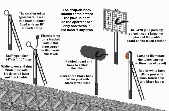
The tokens were set up on a post by the track with the arm loop angled towards
the line (for this duty the older 'staff' or baton type tokens were also fitted
with the eighteen inch diameter loop). The driver or fireman would reach out
and catch the loop on his arm as the train passed. To drop off the tablet there
would be a corresponding post fitted with a large hook and backed by a padded
board or a large square net so the train crew could simply drop the ring onto
the hook as they passed. This avoided the risk of the token bouncing and
getting under the wheels of the train which would damage it and prevent it
working. To allow operations at night both the token post and the catching post
would either have a bracket with an electric lamp on it fitted to the post
itself or a separate post carrying an oil lamp, facing away from the direction
of travel.
Fig___ Typical tablet exchange apparatus
The advantage of having
all these posts and lamps on a layout is that they can help arrest the eye so
they serve well at the entrance to a fiddle yard if a signal box is close by.
The disadvantage is that (as far as I am aware) making the token appear and
disappear is difficult without resorting to a rotating section of ground with a
loaded and empty post on the two sides. On balance it is probably better to add
a small timber platform with a handrail (to prevent the signalman falling under
the train) and a lamp by the track side. The lamp at least can be made
operational for 'night running'. With a bit of care you can cut through the
signal box steps (before assembling the model) about half way up and insert a
timber landing extending toward the track. You would need to replace the
handrails with home made ones and these should run round all three sides of the
platform.
At speeds above about twenty miles per hour catching the
ring on your arm was likely to cause injury so, once the smaller tokens were in
use, automated token exchange apparatus was developed. These consisted of a
trackside post with swinging arms with spring loaded clips, one to hold the
pouch the other to catch the pouch on the loco. The arms were swung out toward
the track when in use. A similar pair of arms were fitted to the locomotive. In
Scotland this system was introduced after several drivers had been hurt
collecting hooped tokens and all these systems allowed the exchange to take
place safely and reliably at speeds of up to about sixty miles per hour.
In actual practice, with the exception of busy commuter type lines,
single track systems can be nearly as efficient as double track lines. I had
this explained to me at length by a professional railway man during a train
journey in America and from memory the difference was in the region of two or
three percent on a rural line. There were several quite major single track
lines in the UK, including several Scottish lines such as the Highland and the
Great North of Scotland as well as the Somerset and Dorset and the Midland and
Great Northern in the south of England. By the later 1920's the first three of
these employed the automatic exchange apparatus but I believe the M&GN
retained the arm-and-loop method to the end.
In the early 1980's
British Railways encouraged the development of Radio Electronic Token Block
(RETB) signalling systems, mainly for the single track lines in Scotland. These
do away with signals by the line side, replacing them with in-cab indicators
and also eliminates the need for mechanical tokens and the staff and signal
boxes required to operate them. This is much cheaper than conventional
signalling and the application of RETB to the more remote single tracked lines
in Scotland after 1984 probably saved them from closure.
The one
drawback with this system is that the signalman is no longer able to monitor
the passing trains for signs of problems such as overheating axle boxes. Hot
axle boxes were already a concern with the steady increase in transit speeds
and to combat this problem British Railways began working on a system of
trackside sensors which would be able to pick up the heat from such a problem
as the train ran by and pass a warning to the signal control centre. (when
updating this document I posted an enquiry on the uk.railway newsgroup on this
issue. The following is based on replies to that post:
Hot axle box
detectors are fitted on most main lines in Britain, approx. every 30 miles. The
earliest models date from about 1965 and were made by Hawker Siddely. I suspect
there are very few, if any of these still in use. The "standard" piece of kit
is made by the Servo Corporation of the USA.)
The only bit I can
comment a little on is HABD - Hot Axle Box Detectors.
They are as you say
still under development & there's still a lot of problems with getting it
right !
What little I know is that they're very delicate/sensitive equipment
that's out in the environment, and they keep going wrong :(
There are 3
types that I know of & they all seem to suffer similar problems..
The
newest on ECML have a problem in that they're programmed with train
configurations, which don't include E* !!!! That really throws
them...
Monitoring Rolling Stock
Use
In the early years of the railways, when tracks ran point
to point, the companies did not take much interest in controlling rolling stock
movement. Within a few years the Liverpool & Manchester Railway was having
to send a locomotive down the line before the morning and evening rush hours to
clear odd wagons on the system. They decided to do a check and sent a team
round to identify and mark any company owned railway wagons, the men found
about four hundred and carved numbers on them. Things were then left for
another couple of years by which time railways had started to join up so that
wagons began to wander and entire trains appeared on the system from other
lines. At this point it became necessary to keep proper records of rolling
stock ownership and to follow them through the system to ensure they were
returned. The railway companies decided that every vehicle was to carry a cast
metal 'registration plate', bolted to the chassis, showing the
vehicle number and the company on who's lines it was normally at home. Some
companies and private owners added painted details on the vehicle sides but in
the event of a fire it was often only the cast plate that survived. Each day,
usually about mid morning, the staff at each station and marshalling yard would
send a report listing all the wagons and vans in their yards back to their
company central office.
Central Traffic
Monitoring and Control
The Railway Clearing House (RCH) was
formed by a group of railway companies in 1842, partly to coordinate payments
for wagon movements through the system and partly to help establish safe
working practices and common standards for connecting railways. Every junction
between companies would have an exchange yard where checkers from the Railway
Clearing House would note the numbers of wagons, vans, tarpaulins and ropes
from each company and send these in to be collated and the accounts drawn up.
In the early days the man in charge of a marshalling yard decided if
additional trains needed to be run to move the stock in the yard on toward its
destination. This resulted in a degree of confusion as extra slow goods trains
were slotted into the already crowded time tabled services. In 1907 the General
Superintendent of the Midland Railway introduced a degree of centralised
control, establishing an office at Rotherham linked by telephone to the yards
and signal boxes in the area. This idea of a central control linked by
telephone to the rest of the system proved a great success and was subsequently
adopted by many other companies such as the Lancashire & Yorkshire, Great
Central, Great Northern, London & North Western, Great Eastern and North
Eastern. Even so these central control points only covered a limited area and
it was only following the 1923 grouping that the whole system became properly
coordinated.
The railway companies divided their territory into
'districts' and each district headquarters received daily reports by telegraph
and telephone regarding wagons in the area. These were summarised and passed
back to the head office where the Superintendent of the Lines Department (some
companies called this the Traffic Department) collated this data. The traffic
department then compiled lists of wagons belonging to other companies and
passed these to the RCH so that any fees due could be dealt with.
The
traffic department were also responsible for arranging for wagons to be
positioned on the system ready for use. If a station master was advised that a
horse was to be moved from his station he would add a code word from his
telegraphic code book to his daily return requesting a horse box be dropped off
ready. Each yard or station would report in, typically twice a day, with a
summary of the rolling stock in hand, and it is worth remembering that
everything was done by staff and a lot was done with pen and ink by armies of
clerks.
Following the lead set by the Midland Railway most of the larger
companies developed basically similar systems of centralised traffic control.
Obviously a degree of planning was required to ensure that the train
would be able to pass efficiently through the system, this would be worked out
beforehand.
Each train departure was reported back to a central control
point, where details of the train and the number of coaches or wagons involved
were written on a card. This card was then placed on a large but simplified
diagram of the railway system covered by that control point. The control centre
could see the entire system at a glance and their permission was required
before a train could set off along the line. As the train moved through the
system its position was reported to the control point and the card was moved
from section to section on the diagram until it reached its destination or
passed to another control centre. Because of this a particular timetable entry,
say a passenger train from Liverpool to Birmingham at a set time, was called a
'diagram' and this term remains the technically correct description today with
trains being 'diagrammed' to run along a certain route at a certain
time.
Not all the pre-grouping (that is pre-1923) companies used these
expensive centralised control systems however, the LNWR for one remained based
on time tables and time intervals with the 'block system' of signalling
(discussed above) as the main protection for trains in transit.
Electronic Traffic Monitoring & TOPS
The LNER
was the first to invest in a system of punched cards to provide a degree of
automation for train control in the 1930's. By the late 1940's tele-printers
(commonly called 'telex') had come into use and following nationalisation
Eastern Region of BR did a lot of work developing automated traffic control
systems. It was 1971 before any money was forthcoming and a new computerised
system based on large IBM all transistorised main-frame computers was procured
form an American company. This new system was TOPS (Total Operations Processing
System), in which every wagon and van, with its load, location and what have
you is listed on the central computer.
Under TOPS three letter
identification codes replaced the old telegraphic wagon description codes and
they are painted on every vehicle. The first letter of the TOPS code designates
the general type of stock, the second the particular type (although some
individual codes refer to completely different types of vehicle). The third
letter defines the braking system, for example the Graham Farish OAA is an open
wagon, of the first design and fitted with air brakes. Details of TOPS markings
will be found in the section on Livery.
TOPS was introduced on Western
Region in 1973 and implementation for the whole network was completed in 1974,
some twenty odd years after Eastern Region's original work. The delay, coupled
with inflation, meant that the total cost had risen to some sixteen million
pounds and by this time the profile of the railway system had changed. TOPS was
devised to handle the million-plus wagon fleet, but by the mid 1970's the
railways were concentrating on bulk shipments, 'liner' inter-city freight
services and merry-go-round traffic.
TOPS proved popular with customers
however as they could directly access the computers and find details of their
own shipments as they travelled through the system. By the early 1980's British
Railways were providing Hewlett Packard microcomputers to senior managers so
they could directly access the TOPS system, these machines were pre-PC designs
based on an 8-bit Zilog Z-80 chip with a tape drive (this was the era before
the floppy disk) and a four inch display screen.
I asked on an internet
newsgroup (uk.railway) whether the TOPS system was still in use in 2003. I
suggested that the original TOPS mainframe computers might be life expired and
need replacing and the software might have been revised. The following is one
of the replies:
It could have been, but they haven't. We still use the same old DOS applications and I believe they still run on the same (if refurbished) computers! The only concession is that interfaces which allow the screen displays to appear on "Windows" PCs have been written.
I suspect the software, and particularly the databases, are of such awe-inspiring complexity that TPTB have taken the line "While it ain't broke, don't fix it". I remember reading somewhere that certain other institutions in a similar position still run their old DOS mainframes etc for similar reasons. It also has to be said that TOPS/TRUST outages are relatively rare and are normally down to communication link failure rather than problems with the operating system. Would "Windows" perform as well?
Things may be about to change. The Central Reservation System is at last to enter the 21st century, so we can look forward to a new era of your seat reservations not being available because the computer system has crashed rather than the current cause, which is that the label printer has broken down.
Your pocket timetables (at least the ones SWT produce) are still edited using the old BR system software and the old mainframe at Nottingham. The hi-tech output comes to us as comma-separated text files (!) which are then manipulated and dropped in modern desk-top publishing software to produce the glossy publication available at all staffed SWT stations. Did someone ask why we don't use our own Train Planners' output directly? We share our routes with no less than five other train operators and two others (as well as TfL) share some of our stations, so we need access to national data in order to satisfy the requirement to be "impartial".
In the early 1980's a European standard system rail traffic control
system began development, originally called the Hermes Project by the mid
1990's this was approaching maturity and had been renamed the European
Rail Traffic Management System (ERTMS). Pending completion of this system
international freight movements continued to be coordinated using the old
telegraphic codes passed via the international telex network.
Following
privatisation Railtrack joined the international working group on ERTMS and
this formed a cornerstone of its forward planning. The idea is to integrate the
functions of network control, traffic management and signalling in a small
number of regional Network Coordination Centres (NCS). These will be linked to
the trains by a secure digital network passing data to and from the trains
on-board computers and passing information to and from the driver using data
panels and voice.
The plan called for the first NCS to be installed to
handle traffic on the West Coast Main Line in the year 2000 with the remainder
being commissioned in the following two or three years. I am not sure of the
current status of this project.