Open Cast Mines & Quarries
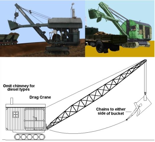
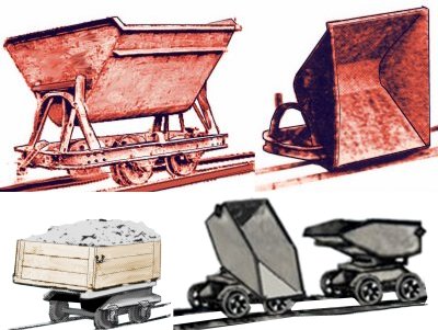
A lot of material lies close to the surface, where only a thin layer of soil (called the 'over burden') has to be removed. Where this is done we get the 'open cast mine' and the quarry. Open cast mining usually features a large pit in the ground where the mineral is recovered using large steam cranes. Some cranes are the conventional 'digger' type but in larger open cast sites 'drag cranes' were used. Drag cranes have a simple open fronted bucket which is dragged across the surface to collect material, the bucket is tipped up to empty it. Drag cranes are common in sand pits but the really big examples were used for quarrying 'ironstone'.
Fig ___ Steam and diesel excavators and a drag crane
Quarries, according to the various Acts governing their operation, are at least eighty foot deep, this could mean a cliff face eighty foot high in the side of a hill or a hole in the ground eighty foot deep. The latter would often require steam pumps to lift out the water and some had cranes suspended from small trolleys running on ropes strung over the hole.
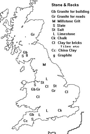
There are a wide range of rock types mined and quarried in the UK, coal and metal ores are considered separately but the map below shows the principal areas associated with the recovery of stone and gravel in the UK.
Fig ___ Stone and gravel mining areas
Sand & Gravel
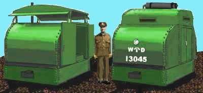
Both sand and gravel are basically composed of rock ground down by the action of water, the former rather more finely than the latter. Their uses are however widely different. Sand is used in the manufacture of concrete, as an abrasive (for which material with a high proportion of garnet is employed) and in the manufacture of glass. Glass works had to be careful about their sources, in the sands from south Kings Lynn and the Isle of Weight were both regularly used and some firms used sand from Reigate. Glass works making flint glass want sand with no iron in it as this would colour the glass (see Glass Works). Sand is generally recovered from open sand pits located in river valleys using drag cranes to recover the material. The sand works at Leighton Buzzard formed the basis of one of Dave Rowe's superb working diorama's and his book on Mechanical Models (see Bibliography) should be read by anyone considering a sand works for their layout. The sand drying works at Leighton was connected to the pit by a 15" narrow gauge railway which used armoured locomotives left over from the First World War to haul trains of side tipping wagons.
Fig ___ Armoured locomotives
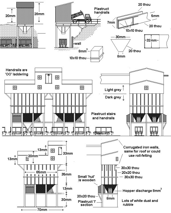
The sand is dried and graded before being piled up ready for shipping (in the case of Leighton Buzzard this was principally by canal). For loading into railway wagons a system of conveyor belts feeding storage silos or hoppers over the track might be employed. A shallow hopper is available in the Heljan range which would serve, intended for use in a Continental loco depot it would need a conveyor feed from a silo or stock pile for this application.
The conveyors could be suggested as described earlier using square section wood strips supported at an angle on iron pylons and clad in corrugated iron sheet. An alternative, with the possibility of moving elements might be an overhead rope-way. In both cases the main works could be off stage, perhaps screened by trees to the rear of the layout.
Some glass requires sand which has been processed to remove impurities, for example flint glass uses sand which has been washed and bleached with acid to remove any traces of iron. This kind of sand is shipped in sheeted open wagons or in covered hopper wagons (Graham Farish offer such a wagon in the range of modern air braked wagons). The glass works at the other end of this operation will be considered later.
Fig ___ Structures associated with a sand drying plant
Gravel is basically what most people would refer to as pebbles, it may be recovered in a similar way to sand or pumped from water filled gravel pits on the coast (when it is often referred to a shingle). Principal sources in the UK are along the South East coast, notably at Dungeness in Kent and Chesil Beach in Dorset. At one time gravel was a major commodity in the building trades, but since the Second World War it has largely been replaced by crushed stone chippings.
After washing and grading the gravel is stockpiled in the open, subsequently being loaded into railway wagons from over track loading silos, or in earlier times by men with wheelbarrows and shovels (note commercially available silos have been discussed earlier in connection with building kits).
Fig ___ Gravel depot
Stone Quarries
Stone quarries can be divided into two categories; those producing large lumps of stone for building work or carving and those which ship out broken stone or 'aggregate', in practice however the former generated quite a lot of broken stone which they sold if they could.
Cut stone quarries generally use wedges driven into existing cracks or man made holes to break away the block from the surface. The blocks are often trimmed to approximate shape and size whilst still attached to the rock face, this was originally done with hand saws and similar tools but powered equipment had appeared by the turn of the century. Granite, limestone, marble and sandstone are the important building stones and slate is used for roofing.
Broken stone or aggregate quarrying is usually accomplished with explosives and results in rubble comprised of lumps from about four foot across down to dust. The large lumps need to be broken down further and up to the mid Victorian times this was often done using convict labour armed with picks and sledge hammers. Hand-breaking of stone using hammers continued into the 1930's at smaller quarries but a good man could only break up perhaps half a ton a day. Steam powered jaw crushers appeared in the mid nineteenth century and rapidly replaced convict labour in the quarries.
Fig ___ Steam stone crusher
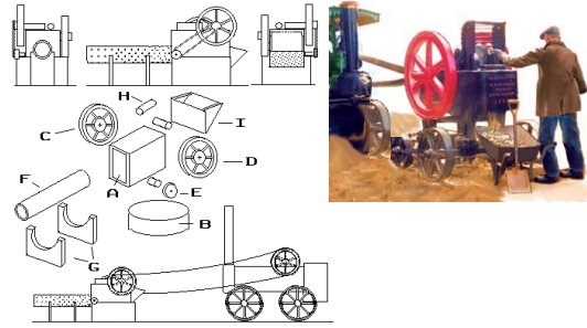
The main body of the unit (A) can be any rectangular section material, solid or tubular, about 6mm wide, 10mm long and 8-10mm high. This sits on a base (B) which is about 6mm high, roughly the same length as the main box but slightly wider. One one side of the main box is the drive wheel (C), this carries the drive belt from the mobile engine. On the other side and mounted at the top is the heavy fly-wheel (D), both these wheels can be represented by small press-studs.
On the same side as the fly-wheel is a smaller wheel (E) which is linked to the centre of the fly-wheel by a belt and operates the 'trommel' (F). To represent the trommel a length of old 'Biro' tube about 15mm long would serve, paint this black with some light grey dry-brushed on. When dry add black dots with a fibre-tipped pen to represent the holes. Any pieces too big to pass through the holes fell out of the far end and were shovelled back into the feed hopper for another run. The two supports for the trommel (G) are solid walls as they serve to keep the rubble divided by size as it falls from the holes. These can be made up from 20 thou card easily enough. A couple of lengths of 2mm rod or similar are glued to the top of the main box to represent the 'works' (H) and a simple hopper (I), made from paper or plastic card is added to the rear.
These machines were usually in the open, perhaps covered by a simple wooden frame with a sloping corrugated iron roof. They were usually arranged to be at a higher level with chutes down which the rubble can be shovelled into quarry wagons or directly into railway wagons.
Mechanically broken rubble, generally no larger than 'half brick' sized (about a 4 inch cube), was screened for size before being loaded into railway wagons. The 'screen' or 'grader' was part of or close by the crushing plant so the oversize bits could be easily re-cycled. The Kibri gravel works mentioned under minerals handling above would serve rather well for a larger stone crusher and loading screen.
The early stone crushers of the 'jaws' type were small enough to be moved about as required and a portable steam engine was often used to drive them. One of these machines would therefore set the scene in a small quarry set in any period up to the end of the 1930's. Even in a larger quarry one of these small machines left derelict on the site helps set the scene, they were usually painted all-over black but add some dry-brushed white to represent the rock dust.
Fig ___ Small aggregates quarries
Aggregates quarrying uses various hard volcanic rocks such as granite and basalt (usually called 'granite' regardless of their actual nature), as well as sandstone and limestone. Broken limestone is used in large quantities as a flux for iron and steel making as well as in cement manufacture. If cooked in a kiln it produces lime which is used in agriculture and in various industrial processes, lime burning is discussed in more detail below.
Both granite and limestone are used as railway ballast and in road making, the hard granite goes into the foundations (called 'hardcore'), the limestone is laid on top. For road building a coating of tar might be applied to the limestone, tar will stick to limestone better than to any other rock. Where road-stone (chippings) were carried it was common to state 'Granite' on the wagon side even if the rock were for example basalt.
In smaller works up to the early 1950's the broken stone might be tipped directly from small wheeled tubs running on light plateways along loading banks in or near the quarry.
Up to the 1950's a common arrangement was to transport the crushed rock to the railway in horse drawn carts of tipping motor lorries which were emptied into wagons from a raised loading bank (see Fig ___). Many if not most quarries handling broken stone invested in light plateways, often carrying small tipper wagons. Probably the most common type was the side-tipper as show top in the sketch below, however there were end-tipping wagons, some of which could swivel to tip sideways, as shown in the lower sketch below.
Fig ___ Tipping wagons used in quarries
At larger quarries handling regular large supplies the graded stone would be stored in over-track loading bunkers. The over-track loader might itself be remote from the quarry (or quarries) it served, connected by a lightly constructed plateway or sometimes a small steam hauled light railway. In the 1960's and 70's there was shift away from narrow gauge railways as conveyor belt systems improved.
A larger quarry or modern aggregate depot such as that as Merehead would require a massive amount of space even in N so a remote railway loading point makes an attractive alternative for the modeller. Smaller loading establishments still exist and suitable wagons for a modern scene would be the Graham Farish or Fleetline PGA 50 ton hopper wagons as used by ARC and Foster Yeoman. One such establishment in the North East uses a raised roadway leading to a simple and quite small hopper, tipper lorries are reversed along the roadway and PGA hoppers are pulled through underneath the hopper. The upper sketch in Fig ___ is loosely based on this prototype in the North East.
The lower sketch is of a rather more substantial loader which incorporates some storage capacity. The sketch is based on a prototype at Wirksworth near Duffield, the crushed rock is supplied from the grader at the main works by a covered conveyor belt.
Both these would serve for layouts set after the mid 1930's, the lorry fed hopper requires a locomotive to move the wagons as the trucks arrive. The larger hopper held enough to quickly load thirty or more wagons, which speeds loading considerably but costs a lot more to build.
Fig ___ Remote Limestone Loading Arrangements
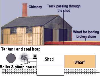
On the Tannant Valley railway the Steetly limestone quarry company used petrol lorries from the early 1930's to deliver crushed limestone to the railway. The lorries were tipper types and a loading bank was provided so they could pour directly into the open railway wagons. Dornaplas offer their Thornycroft lorry in a tipper version (DRN8) for pre-war layouts and their Ford lorry as a tipper (DRN14) for more modern layouts. On the same siding was a large building in which they produced tar coated stone chippings for use on the roads, known in the industry as 'blacktop'. Note this would be associated with a limestone quarry as this is the best stone for tarred chippings.
There are a couple of photographs of such a facility in the late Mike Lloyd's book The Tannant Valley Railway. I do not have my copy to hand bur from memory the siding was a dedicated private siding at some remote location, the loading bank was long enough to hold perhaps ten wagons in the open and a further three or four could fit inside the tin shed covering the tarred chippings plant at the buffers end of the siding. The plant consisted of a rotating metal drum, the chippings were put in and hot tar spreayed or poured in as the drum rotated, giving the stone an even coating.
The building if built to scale would need to be something like eight inches long by four inches wide in N, but it was rather nondescript in character. The original has a corrugated metal walls and roof but 'random stone' walls would be reasonable and easy to model using embossed card. You would need some form of chimney, but one is available as part of a set of 'industrial fittings' from Ratio, and as part of a 'boiler house' from Kestrel.
Up to the 1930's the tar would be from the gas works and would arrive either in large wooden barrels (black and carried in unsheeted open wagons) or in elderly, often rectangular, black tank wagons. If you opt for barrels these can be unloaded at the wharf, if you decide to use tank wagons you need a tar tank (less common I believe). The tanks used were usually a vertical cylindrical tank about ten feet in diameter and thirty feet high which was steam-heated and hence mounted on a brick plinth. The tarred chippings were not carried in Railway Company wagons after 1921, PO stock, often iron bodied, were used after that date. The wagons used were often three plank and no higher than five planks (quite a few were iron bodied). A Peco 'sand' load insert, painted black, would serve for the load. I believe this traffic started in the early 1920s and had faded away on the railways by the later 1930s.
Fig ___ Simple aggregate loading point and tarred chippings plant
These days the tar coating works is as often as not remote from the quarry and closer to where the material is to be used. As recently as the late 1980's BR was using old HTV twenty one ton hopper wagons to deliver the crushed limestone with the bitumen coming from oil refineries in four wheeled tank wagons. Taylor plastic models offer a conversion kit for the Peco 45 ton long wheelbase tanker to produce a standard bitumen tank wagon. The tarred chipping would then be sent out by road but the basic facilities would remain as a simple shed (probably with a lot of roof ventilation) to contain the rotating drums in which the chippings are tarred, I would asume these would probably be gas fired by the 1980s.
The other end of the aggregate business might be a builders merchant's private siding but was often the local station goods yard. The goods yards were progressively closed in the 1960's but with the construction boom of the 1970's purpose built unloading points were built, in some cases redundant coal drops were utilised.
Since the 1970's unloading points would see regular long trains of PGA stone hoppers of the type released by Graham Farish, these are bottom discharge wagons requiring a raised drop. The stone might simply be poured into the under track bays for loading into lorries by mechanical shovel or a mobile hopper with a conveyor belt might be positioned in a bay to directly load road vehicles. This latter idea means you can save some space as the storage facilities could be relatively small scale.
Where one-off flows occur BR have used bogie and four wheel tippler wagons delivered to a convenient siding and unloaded by a small crane equipped with a grab.
In XXX Redland Stone developed a self-unloading stone train using hopper wagons equipped with diesel powered conveyor belts, these pass the load to a bogie wagon equipped with a swivelling boom conveyor for unloading.
These days minerals such as limestone are often shipped by rail to a convenient point where they are stockpiled and delivered by road. In some depots tippler wagons are used for this traffic, the tippler itself often being enclosed in a large building from which the stone is moved by mechanical shovel. The example shown in the sketch below was drawn from a photograph taking in the 1980's of a depot in Scotland handling crushed limestone.
Fig ___ Modern aggregate unloading facilities.
Slate
Slate is probably the first thing which springs to mind when quarries are mentioned. This material was principally produced in North Wales, notably at the quarries in Llanberis and Bethesda although there were also quarries in Scotland, the Lake District and at Delabole in Northern Cornwall. Welsh slate is dark grey, Devon slate is blue, Skiddaw slate from the Lake District is green and purple and Ballachulish slate from Scotland is black.
The graphite in Lake District slate allowed the development of the pencil industry.
Most slate quarries were located in the hills and most Welsh slate was shipped by sea, so there were often narrow gauge lines built, often gravity-operated, running down from the quarry to the docks. The well known Festiniog railway was built to carry slate down to the docks at Port Maddock XXX Spelling XXX
The slate is these days blown off the face of the quarry with explosives (in earlier times they hammered in wedges to break blocks off the face). The resulting blocks are sorted and some are cut into large slabs using rotary saws housed in cutting sheds. Slate slabs are used for electrical insulating panels in large switchboards, billiard table tops and it was once used for sinks and draining boards. It is most commonly associated with thin oblongs used as roofing material, cut to standard sizes by hand, then loaded on-edge into the small narrow gauge wagons for sending down the mountain. The narrow gauge line might reach all the way to the docks or it might arrive at a transfer yard where the narrow gauge wagons were loaded onto standard gauge transporter wagons. (See Fig ___).
Slate quarrying produced a great deal of waste, something like seventy five percent of the material cut from the rock ended up on the surrounding tips. The slate processing was often done in buildings sitting on top of these tips, which makes a full size slate quarry a difficult proposition for a model railway.
A better option is therefore to have a set of exchange sidings where the narrow gauge wagon way meets the railway proper.
When shipped by standard gauge railway the slates were stacked on-edge resting of a bed of bracken or straw in low-sided wagons, typically three plank types.
Fig ___ Slate exchange sidings
Cut Stone
Other than slate the three principal types of building stone and aggregate shipped in the UK were sandstone,: granite and limestone.
Sandstone comes in a wide range of colours and textures, including grey millstone grit shipped from Derbyshire to Sheffield for the grinding of steel, the whitish Scottish stone used in Edinburgh and shipped down to London, and the red stone of the Midlands and elsewhere. Millstones for use in grinding corn disappeared in the early part of the twentieth century following the introduction of mills with steel rollers.
Granite can range from white to red, depending upon the location of the quarry, much used for building bridges and lighthouses because of its strength. Most of Aberdeen is built of a pale granite, and the surrounding area has produced considerable quantities of the stone. Other granite quarries were located in North Wales and Westmoreland, the largest sources were however in Devon & Cornwall, where there have been several thousand quarries at one time or another since the nineteenth century. Building blocks were sometimes shipped having been roughly shaped to within a couple of inches of the desired size and shape but the finishing was more commonly done on site at the quarry. Kerb stones, stone setts for roads and inlaying in tram and railway lines were produced from granite, a large quantity being shipped by rail or sea from Scotland to London.
Limestone is a white or whitish rock, used in blocks for building, kerb stones etc. or as rubble in steel and cement manufacture or to make lime (discussed below). Cement is made by roasting limestone (Calcium Carbonate), clay and coke and ends up as a mix of calcium silicate and calcium aluminate, this sets hard when mixed with water and will set under water (unlike mortar)
Limestone was an important building material until the decline in its use after the rebuilding of London following the second world war. Portland Stone is perhaps the most famous building limestone, St Paul's Cathedral is built from it and cement got the name Portland as it resembled this rock. Pulverised limestone dust, carried in sheeted PO wagons, is used in mines to prevent explosions, ICI was a major supplier and wagons used for this traffic by this firm were marked 'For Calbux only' - cal being calcium carbonate or lime, and bux referring to Buxton, a major source of supply of this material. Chalk is a form of limestone, principally used in the manufacture of cement in the older 'wet' kiln process (see Cement).
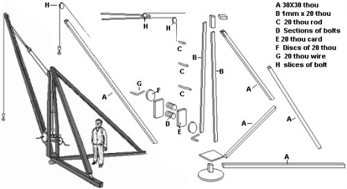
The nature of the stone being recovered has considerable effect on the nature of the quarry, its installations and the appearance of the finished product. The 'Shire Albums' range of small booklets includes a useful book "Quarries and Quarrying", which contains several pictures of quarry operations, although little on the connection with railways. The standard kit for loading cut stone onto railway wagons was the portable derrick crane, there were many variations on this basic idea, many of which are not difficult to make. The example below is a small hand operated type, using the Ratio OO scale LNER lattice signals kit you can produce a much larger type to the same basic design but steam or diesel powered.
Fig ___ Basic derrick crane
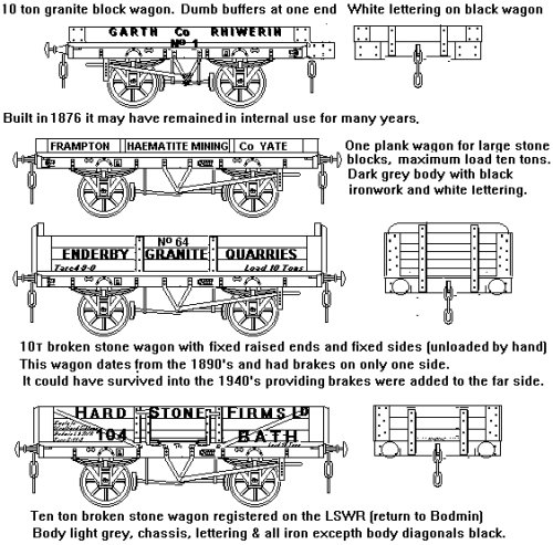
Stone could be shipped either as blocks for building (or cladding buildings), cut into kerb stones or road 'setts' or as rubble for road building, railway ballast and more recently the production of concrete. The wagons used for cut stone were generally private owner, usually of two or three plank sided types. Blocks would be laid on a bed of bracken to cushion them in transit. Stone blocks were often moved from the quarry face to the railway on small horse drawn trolleys, running on iron 'plate ways'. Is worth noting that there have been extensive stone mines operating underground in areas where the stone was only found at some depth most of these being of the 'drift' type. Where the bed of rock sloped down steeply it was necessary to have some mechanical aids to lift the cut stones up the adit, and one picturesque option is the capstan operated by a horse as shown in Fig ___ above.
Fig ___ Wagons for cut stone
Lime
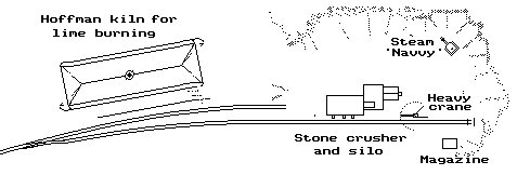
Lime is produced in a kiln or oven in which limestone rock is heated to over nine hundred degrees centigrade, reducing it first to rubble, or if continued to powder. The lime burning kilns tended to be quite large even in 'N', and they came in a variety of designs. One of the more common was the tapering square tower, in N gauge these would be perhaps 30mm wide at the bottom, tapering to about 20mm at the top and about 60mm high. They were usually brick built structures, often leaning up against a cliff face as this meant the stone could be tipped in at the top without having to be hoisted up the outside, there were large (six foot wide and six foot high) arched openings at the bottom where coal was carried in. Hoffman type kilns were also used for burning lime (see Fig ___) and the drawing below shows a Hoffman type kiln located in the quarry itself. A real example of such a kiln in a quarry was located close by the old Settle and Carslile railway route and this continued operating into the 1960's. A very detailed description of this works by Mr. M. R. G. Trueman was published in the Industrial Archeology Review Vol.XIV Number 2 (Spring 1992) which should be available through your local library.
Fig ___ Large quarry with lime kiln
The limestone was carried on a narrow gauge plate way in small open sided trucks. These had ends about two foot high and the rock was piled perhaps three foot high, tapering inward toward the top. After burning in the kiln the lime was dug out by hand and moved in wheelbarrows to the railway loading dock (laid alongside the kiln) where it would be tipped into 'cottage topped' wagons as available from Peco and Graham Farish.
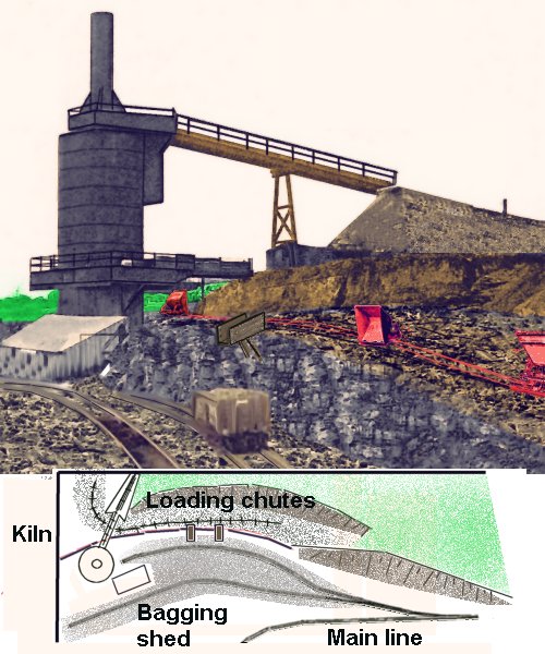
Not all kilns were of the Hoffman type however, some were vertical kilns and some of these were tall structures mounted in the open rather than the more common mine-shaft type. The sketch below is loosely based on the kiln at Rogiet (near Chepstowe in Gwent, formerly Monmouth). The sketch shows how such a kiln could serve as a scenic break set into a corner of the layout, allowing the quarry proper to be off-scene with a narrow gauge line feeding the loading chutes on the upper siding. The second siding runs to the lime kiln but also serves as wagon storage.
Fig ___ Large vertical lime kiln
^
Go to top of page