Industrial and agricultural
vehicles and equipment
Note - For detailed information on cranes and lifting equipment see also 'Wagon Loads and Materials Handling - Materials Handling' and for more information on trucks and lorries see also 'Appendix One - Roads and road traffic - Road Vehicles - Commercial Vehicles'
This section discusses the sort of vehicles and equipment that can be used to detail to an industrial or agricultural scene on a layout. More information on the vehicles and cranes described below can be found in the section on Wagon Loads & Materials Handling in the sub sections Road Vehicles, Industrial and Farm Machinery and Materials Handling - Hoists and Cranes respectively. Barrels, sacks, cases, crates and other packaging that represent much of the 'clutter' in an industrial scene are discussed in Appendix One - Packaging Materials & Containers.
Tractors and tugs
Industry often has to move large and heavy materials about the place, one option is to put it on a trailer and tow it with a tractor. Often surprisingly vintage equipment would be retained on the farm or at a factory, for example steam lorries were penalised from the early 1930s by road taxes based on axle weights, however they remained in use in larger factories such as steel works, dockyards, engineering works and the like where this tax did not apply.
Small four wheeled trailers could be pulled by hand or towed by the little Lister three wheelers described below but for bigger jobs the first option was horses, later supplemented (but never completely replaced) by steam traction engines (which could also be fitted with a crane). Steam lorries were also used within the works, carrying things or towing trailers, my local gas works used a steam lorry to top tanks of ammoniacal liquor about the works well into the 1950s (although by this time it was not used on the roads because of the high tax on steam road vehicles). See also Appendix one - Road Traffic - Steam, Motor and Electric Commercial Vehicles.
By the 1920s industry was making regular use of oil or petrol powered agricultural tractors.
Fig ___ A XXX tractor from about XXX
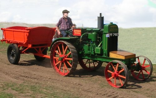
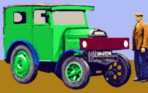
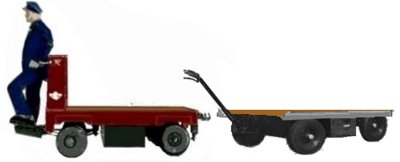
Agricultural tractirs were used in larger factories unaltered other than having road-going tyres (sometimes solid rubber, sometimes pneumatic). Some however were more extensivley modified for use as tugs. The example shown below dates from the 1930s, it has road-going pneumatic tyres and has a cab fitted, the sketch is based on a photo of such a machine towing a heavy trailer in the 1930s.
Fig ___ An industrial tractor
The Co-Op in London used an agricultural tractor (fitted with a cab) in the 1930s to tow the road-rail milk tank wagons from the railway yard to their dairy. The LNER (and presumably other railway companies) operated similar tractors, one job being to tow the road-rail tank trailers used for milk traffic from the station to the factory.
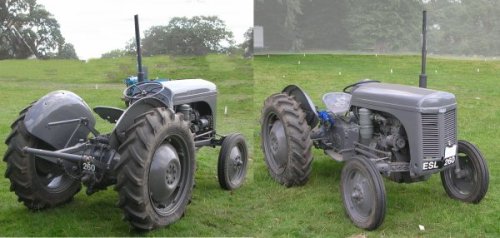
Prior to the second world war most agricultural tractors were painted red with a few painted green but shortly after the war Ferguson's of Coventry introduced their revolutionary T series tractors which were painted grey. These had a hydraulically powered frame at the rear, called a three point linkage, and a rotating power take off point mounted under that. The Ferguson was designed to use specially built equipment fitted up to use the linkage and power coupling on the tractor. Ferguson provided a big range of equipment including ploughs, grass cutting shears, and powered muck spreaders. The Ferguson system meant that one man could both drive the tractor and operate the equipment and it revolutionised farming practice. Naturally industry found occasional uses for this machine as well, although the primary function of industrial tractors remained the towing of heavy bits of kit about the place. Farm tractors up to the 1930s a lot of farm tractors had metal plates on the driving wheels, intended to provide better grip, in industrial use these were removed and solid rubber tyres were fitted. Solid rubber tyres remained in use on industrial tractors into the 1950s although by then farmers were nearly all using inflatable tyres (other than on very old machines which lacked the appropriate wheel rims). As industrial tractors were often used on an occasional basis there were often older designs seen in factory yards some years after they had been repacked on the farms.
Fig ___ A post war Ferguson T series tractor with its three-point linkage
Trolleys and Trucks
There is considerable overlap between industry and agriculture in the use of small utility vehicles, a small run-about truck serves well on a dockside, in a factory and at a market garden whilst a tractor can haul loads both in a works or on a farm.
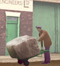
A lot of work was done by hand up to the 1970s, and a simple piece of kit such as a 'sack truck' could be pressed into service for some surprisingly bulky loads. The example shown is a bag of rags being shifted in an engineering works.
Fig ___ The simple sack truck
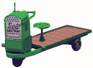
Some very small three-wheeler motorised machines were built for factories and farms, notably by Lister (who also built four-wheeled versions for use on narrow gauge railways). The example below is from the Lister 'Auto Truck' range from the 1930s, the engine powers the front wheel, the entire engine and wheel assembly being pivoted so the thing could turn in its own length. They were widely used in industry and on the docks (notably at fish docks where they transported the heavy fish boxes to the waiting railway vans).
Fig ___ Lister 'Auto Truck'
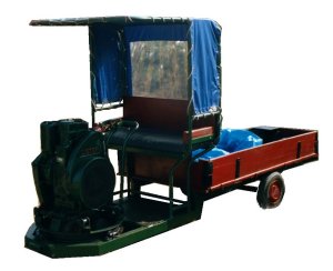
These remained in widespread use into the 1960s, the rather more up-market example in the photo below was used by a market garden type farm near Oxford. It was photographed at a steam plough contest in 2002.
Fig ___ Lister 'Auto Truck' with canopy frame
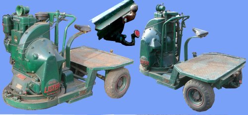
One rather less common variant was the diesel engined autotruck, the example shown below was built as a 'tug', it has a curiously shaped hook at the rear (and has since had a standard ball hook added). Unfortunately this example has lost the original punched metal 'bucket' seat and has a bicycle saddle instead, this one was photographed at the Astle Park show in 2007.
Fig ___ Lister diesel 'Auto Truck' tug
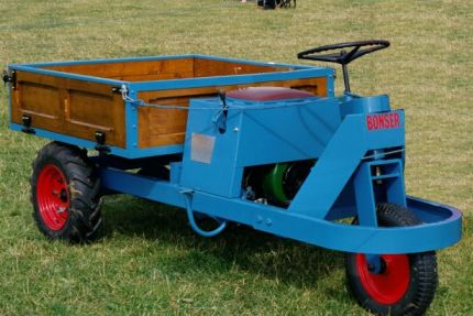
These small machines had exceptionally tight turning circles common on three-wheeled machines, but these small types were confined to internal use in factories and did not venture out onto the roads. The example below, dating from about 1950, was photographed at a steam and classic motor show in about 2002 and has rear wheel drive.
Fig ___ A Bonser three wheel truck from about1950
The small wheels on these machines can be represented in British N Gauge with slices cut from a 1mm diameter plastic rod (2mm in OO gauge).
One common bit piece of equipment, introduced shortly before the First World War, was the electric trolley or truck. These came in a range of sizes, some had a driving platform (with a 'dead man's' pedal that had to be pressed), others had a steering handle and the operator walked along in front (or behind) the thing.
Fig ___ Electric trucks
Factory and farm mobile cranes and platforms
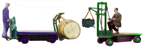
The small electric trucks could be fitted with a range of attachments to handle specific jobs, in the days before the 'fork lift truck' (that is pre world war two) a crane attachment was a common option. These came in all shapes and sizes, some built by specialist firms, other thrown together at the factory where the machine was being used. The examples below are sketched from photos taken in the 1920s. The example on the right is a purpose built machine, it uses a screw-drive to move the lifting frame up and down the support arms.
Fig ___ Electric trucks with crane attachments
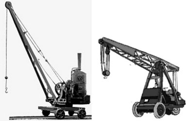
Cranes, often small, featured in many industries, where the works were large a mobile crane on a steam traction engine might be used, in smaller works, stone yards, wood yards and the like a small steam crane on rails was more common. In the 1930s small petrol engine cranes appeared in some numbers, and in a range of sizes (the example shown below is quite a large variant). These generally replaced the steam cranes in more prosperous works, but in wood yards and the like the old cranes soldiered on into the 1960s or even 1970s.
Fig ___ Small steam crane on rails and 1930s petrol crane
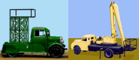
During World War Two a lot of progress was made on the development of hydraulic systems, including the all important seals used on rams. This allowed the development of a range of machines using hydraulics, replacing the complex combinations of pulleys and wires. The examples below are lifting platforms used to access high things such as street lamps, the motor truck on the left is a 1930s vehicle, the hydraulic machine on the right was sketched from a photo taken in the mid 1960s.
Fig ___ Platform trucks
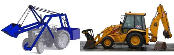
One area where hydraulics made a major difference was in the bucket loader, the examples below show a 1950s machine (similar vehicles had been in use since the 1930s) and the mid 1960s JCB which also has the 'back hoe' mounted on the rear. The front bucket on the JCB can be of various sizes, fitted with chains it can be a handy little crane for moving heavy kit about. The rear mounted backhoe can also be fitted with a range of buckets and is very useful for digging trenches. The backhoe can also carry a hydraulic drill, a steel spike repeatedly hammered by a hydraulic drive and used to break up road surfaces in place of the man with pneumatic drill (but just as loud).
Fig ___ Front loaders
Welding and cutting metal
Welding joins two pieces of metal together by heating them until they soften then pressing them together. The technique dates back to about 4000 BC the weld being formed by forcing the red hot metal edges together after heating in a furnace. Blacksmiths form welds in this way when making (for example) a ring of wrought iron. This remained the only way of welding metal until the mid nineteenth century when an American engineer called Elisha Thomas developed electrical resistance welding in which an electrical current is passed through the joint between to pieces of metal. Where the joint is rough the electrical resistance is high and the joint heats to the point where the metal melts and fuses together. Resistance welding was used to make welded steel pipes as early as the late 1880's.
The electric arc was originally developed in 1807 by Sir Humphry Davy (1778-1829) but it was 1885 before someone devised an electric arc welding kit and 1890 before a Russian developed the consumable electrode which made it practicable. In 1904 the coated electrode (as used today) was invented but it was the 1920's before arc welding became common. Arc welding produces a very bright blue-white light, a lot of hard ultra violet light and even x-rays, if you look at it with the naked eye it will blind you very quickly indeed. Welders wear clothing with long sleeves and gloves to protect their skin and use a metal face mask with a darkened window set into it when working. They have to move the mask out of the way to see when the arc is not struck and early welders held the mask in one hand, by the early 20th century a lot of masks were fitted with a head band and had a hinged dark glass filter that could be flipped up when the worker needed to see. By the early 21st century electronic masks had been developed in which the window is a liquid crystal lined to a sensor, as soon as the arc is struck the window darkens, clever but I am not sure I would rely on it.
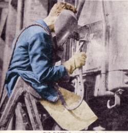
The illustration below shows a man welding on one end of a railway carriage, note the face mask, heavy gloves and leather apron to protect him from any drops of molten metal.
Fig ___ Man arc welding (1930s)
Oxy-acetylene welding dates from the early 20th century, developed from gas cutting which dates from 1900 when the torch was invented by one Edmund Fouche. Oxy-acetylene gas torches can be used to weld two materials together or to cut through metal (hence the common term 'gas axe' for a set used in cutting).
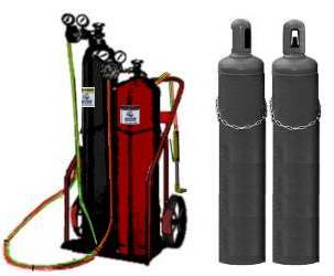
The two cylinders are different sizes as you use different proportions of fuel and oxygen for different jobs and they are at different pressures. The two hoses are coupled together, on early sets the fuel line was red and the oxygen line black (the hoses were sheathed in rubber and nearly an inch thick) on more modern sets the fuel line is red and the oxygen line green, they have left and right hand threads to prevent them being connected the wrong way round. Welding and cutting require two different heads on the torch, cutting torches have a trigger to blast pure oxygen into the cut (this reacts with the hot metal forming an oxide slag which falls away). In a workshop the cylinders will be chained to a wall, for mobile use the two tanks are usually strapped to a simple two-wheeled trolley with the hose looped over the handle when not in use. The sketch below shows a typical 'gas axe' kit (it is a gas cutting set as it has the extra lever on the handle of the torch) and gas cylinders with the safety caps in place
Fig ___ Portable Oxy-acetylene kit and capped cylinders
The British Standard Colours for cylinders were established in the early 20th centry, the oldest reference I have relates to the 1932 standard but I am not sure if that was the first. These colours were approved and retained in the 1973 British Strandard, prior to the introduction of a europe wide standard (although I am not sure when that came in). Oxygen cylinders were plain black (medical oxygen had the top dome painted with white and black quarters), acetylene were plain maroon, hydrogen, coal gas and propare were all plain signal red. In the 1973 version of the code there was an emphasis on labeling the bottles with the name and formula of the contents.
Oxygen and the fuel gasses used in this equipment are all highly dangerous, in the 1950s a fitter on a merchant ship had been working with a gas cutting set in a ship's engine room, he had been changing the bottles and had managed to release a lot of oxygen which had permeated his clothing. He then took the lift up to the main deck and on the way lit a cigarette, I gather there was not a lot of him left.
Acetylene is probably the most common fuel used, however it is tricky stuff to work with as at higher temperatures and pressures it becomes unstable and can explode. Inside the acetylene cylinder there is some form of absorbent material and the cylinder is half filled with acetone. The acetylene dissolves in the acetone, making it more stable. It is still dangerous however, I know of one case in the 1950s where a cylinder trolley fell over sideways, catching the head of the acetylene cylinder on a steel bench and breaking it off, the cylinder set off like a torpedo and punched through a thick brick factory wall before it came to rest. Oxygen is even more dangerous as it is under a higher pressure in the cylinder. When tanks secured to a trolley are being moved the protective cap should always be screwed in place to prevent the valve being knocked off in this way (although in practice this is seldom done).
Hydrogen can also be used as a fuel, although it does not burn as hot as acetylene it is cheaper and it can be pressurised safely so it is used for under water work (because of the pressure underwater acetylene becomes dangerously unstable at a depth of about 30 feet or 10m). Other fuels such as propane, gasoline and even propylene can also be used with oxygen for cutting and welding, however acetylene remains the most common option.
Another option is 'thermite welding' in which a case is built round the joint and filled with a material called 'thermite' mainly powdered aluminium with some powdered iron and magnesium. When ignited this mixture burns hot enough to melt steel. One application for thermite welding is joining sections of railway line together.
^
Go to top of page