Gas Works and Coke or Coal Tar Plants
Coal consists of carbon mixed with a range of impurities, if it is heated in a sealed container with no air (pyrolysis) the various impurities in the coal are driven off as a thick dirty smoke to leave almost pure carbon in the form of coke. If the smoke from the retort is allowed to cool tars and oils are condensed out, leaving a fairly clear gas which can be used as a fuel. This process was developed by a William Murdock in the 1790's and his 'coal gas' was soon developed for domestic and industrial use.
The tar and oils that were condensed out of the gas were initially a waste problem for the gas works but it was not long before people began looking at these tars and oils to see if they contained anything of value. With the water content reduced the tar was found to be useable as a protective 'paint' on buildings (rammed earth cottages had a black strip of tar around the base of their whitewashed walls where the rain might cause most damage). By the early nineteenth century someone had developed a method of producing 'roofing felt', essentially a woolen fabric coated in tar and then covered by sand. Roofing felt was popular in Germany and the USA throughout the nineteenth century but was less common in Britain other than on flat roofed buildings.
Coal gas tar consists on a range of materials, basically divided into 'Naphtha' (valuable) and 'Pitch' (less valuable). Naphtha is a generic term used for the assorted light distillates of coal tar, wood and petroleum. A ton of coal produced about seven and a half gallons of tar, of which about 60% ends up as 'pitch' and only about 5% constitutes the more valuable elements in the naphtha. One of the first valuable by-products from coal distillation was creosote and by the 1860's the remaining lighter fractions were distilled to obtain benzene, toluene naphthalene & etc. Some of these fractions ended up in the gas being produced and from the 1870's Benzol was being recovered from coal gas at many larger works. The process of recovering the useful constituents of the tar is more fully discussed in Lineside Industries - Coal and Wood Tar Distillers, the descriptions below relate only to processes commonly applied at gas works.
In the larger gas works the gas from the condensers was passed to the Benzol plant where it was re-heated to about 170 degrees centigrade to recover these lighter distillates. A ton of coal only produced a few pounds of Benzol. Benzol is a mixture containing mostly benzene but also toluene, anthracene, xylene and the aniline so important to the dyestuffs industry. Aniline is colourless but turns brown on exposure to air and light, it is one of the most important of the organic bases and as well as dyestuffs it is used herbicides, fungicides, photographic chemicals, in the making of urethane foam and pharmaceuticals. Over half the dyes used today are the nitrogen based 'azo dyes', the basis of which is naphtha. Since the 1930's these chemicals have mainly been obtained from petroleum oil at oil refineries.
The unrefined naphtha, a deep amber to dark red liquid, was often shipped out for further processing in drums from smaller gas works, or in tank wagons for larger establishments. Coal tar naphtha contains the more valuable light distillates usually lumped together under the general term 'Benzol'.
The tar could be processed on site, first being passed to the Naphthalene plant where it is the again heated to a slightly higher temperature (200-250 degrees centigrade). From this you can take the naphthalene direct as a white flaky powder or get heavier oils including carbolic oil. At still higher temperatures (up to 400 degrees centigrade) you get creosote oil, a yellowish to dark green-brown liquid (also known as tar oil and occasionally as liquid pitch oil). The remaining tar, a thick black oily liquid is called 'pitch', was stored on site in a pit and shipped out in barrels or Graham Farish type tank wagons to be used for tarring roads and as a wood preservative.
During the Second World War experiments were made with introducing hydrogen into the tar to produce something akin to fuel oil (the process was called 'gasification') but this was expensive and was not followed up at the time. More recently there has been a resurgence of interest in this process, but this is mainly based in the USA.
The residual coke from the gas works was rather soft and could only be used as fuel, although it has the benefit of being smokeless. Most would be sold locally and hauled away by road in sacks or two wheeled carts, although some might be shipped out by rail for delivery to a coal merchant (the coke from the gas works was sold as Firemax after Nationalisation of the gas industry).
Gas Works
Prior to the development of natural gas supplies in the late 1960's and early 1970's gas was made from coal in a local gas works. The town gas works is a popular adjunct to model railways set in any period up to the 1970's, they were built in sizes to suit almost any size of layout and generated an interesting and regular traffic for the line. At the gas works the sealed containers used to cook the coal are called retorts, originally made of metal they changed to moulded fire clay in the 1830's. The evolution of coal gas retorts is illustrated in Fig ___, note that the cross sections shown are generalised to show the basic changes, they are not accurately based on specific prototypes.
Fig ___ Gas retort buildings
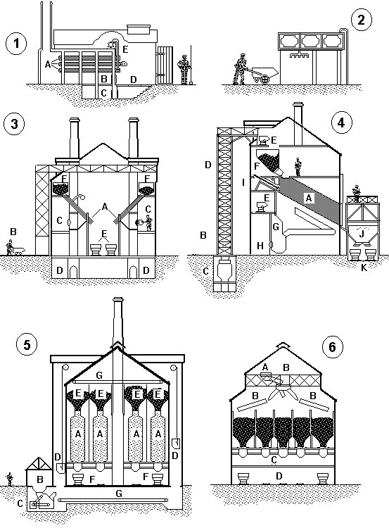
Fig ___ (1) shows the early form of retort house, there were between five and seven retorts (A) arranged rather like a bank of torpedo tubes in a submarine. The coke used to heat the retorts was shovelled into the furnace (B), which gas works people called the 'producer'. Ash from the producer fell through the fire bars and collected underneath (C), the floor of the retort house was made up of removable plates (D) to allow the ash to be periodically shovelled out.
The gas was drawn off from the retorts through pipes (E) which fed a single main pipe called the 'foul main' which lead out to the purification plant.
Once all the gas had been removed the hot coke from the retorts was dug out using long handled rakes and tipped into metal wheel barrows (called coke barrows). These were then quickly wheeled to a small brick or stone shed where they were sprayed with water to cool the coke down. An example is shown in Fig ___ (2), in this case there is a small water tank on top of the structure, fed through a small pipe to the right. The coke would then be graded, probably using angled bars, stockpiled and sold.
In the mid nineteenth century, as the size of retorts increased, mechanical stoking was introduced but this was not a great success. In the 1880's someone thought of building angled retorts, filled from the top and emptied from the bottom with the assistance of gravity. Fig ___ (3) shows the general arrangement. The angled retorts (A) are supplied with coal from bunkers (F) in the upper part of the building. The coal is wheeled in from the stock pile in small trucks (B) which are then hoisted up the outside of the building. A separate 'charging stage' (C), also fed from the hoist, allowed the crew to stoke the 'producer' to heat the retorts. The ash from the producer fell through the fire bars to an ash pit (D) in the base of the building. The hot coke was emptied into small trucks (E) or onto a conveyor belt, quenched with cold water, graded for size and stockpiled.
The logical development was to build bigger retorts and Fig ___ (4) shows a cross section of a retort house dating from the turn of the century. The retort in this case was made of metal and on the plans it is called a 'chamber oven' (A), the building was still called a retort house however. The coal is supplied by a conveyor system (B) from the stockpile and fed into a crusher (C). A gravity bucket hoist (D) lifts the coal into the upper part of the building where it is distributed to the storage bunkers (F) using small tipping trucks (E) or a conveyor system. Small tipper trucks feed the vertical producers (G) through the top and the ash is extracted at the bottom (H). When all the gas has been extracted the coke is emptied with the assistance of a powered ram (I) via a power operated door into a quenching trough (J) and from there it is fed into tipper trucks (K) to be hauled away, graded and stockpiled.
Fig ___ (5) shows a highly mechanised retort house from the 1930's. The retorts (A) are vertical and they are heated with carburrated water gas from an on-site plant. Unlike the older designs the retorts operate continuously with the coal passing down through them changing to coke by the time it reaches the bottom. Coal is supplied via lorry or railway wagons to the loading point (B). Here it is crushed by the machinery (C) then hoisted in a gravity bucket conveyor (D) to the bunkers (E) at the top of the building. The hot coke is mechanically extracted at the bottom of the retorts and is carried away on conveyor belts (F) to be quenched, sorted for size and stockpiled. Conveyor belts under the floor of the building (G) move the coal from one side to the other and feed the hoppers at the top.
Fig ___ (6) shows a coke grading plant which might be built onto the end of the retort houses shown in Fig ___ (3), (4) or (5). The coke is first quenched with cold water. A gravity bucket conveyor lifts the coke into a hopper (A) at the top of the building. The coke is then fed through a series of rotating screens (B) which grade it for size, emptying into the hoppers below. From the hoppers it can be bagged in a bagging plant (C) or dropped straight into road or railway vehicles (D). As a rough guide a hundred tons of coal would typically yield seventy tons of coke.
The dirty smoke generated in the retorts is drawn off through pipes, this smoke contains the desired gas as well as a range of impurities, some of which can be recovered and sold for various purposes (gas works were noted for the smell of camphor). What happens to the smoke depends on the age and size of the associated works, in early gas works it was passed to a condenser consisting of a set of tall iron pipes usually in the open air into which a spray of cold water was injected. The cold water condensed the tars and other oils in the gas and washed it into a tar pit from where it was sold as a wood preservative.
The remaining gas was then passed through water into which lime had been mixed to remove more of the impurities (mainly smelly sulphur compounds) and stored in cast-iron (later riveted iron plate) cylinders called gas holders. Gas holders are often called 'gasometers' although there is in fact no such word. Inside there is a water bath and the gas holder sits in this rather like the plastic cap of an aerosol sitting in a cup of water. The gas is trapped above the water and as the holder fills with water it is lifted up, the weight of the metal providing the pressure for the gas (a booster pump was often required to supply mains pressure as demand and the area being served increased).
Up to the mid 1830's the gas holders had to be encased in a brick building by law. These buildings were usually hexagonal in form, often with a prominent roof ventilator, and a surviving example may be seen at Warwick although the tank holding buildings are now offices. This crude secondary containment was actually highly dangerous, in the tank there is no air so the gas cannot explode, but trapped between the tank and the building an explosive gas-air mix could form if the tank leaked. If the mix was ignited the brick building would in effect become a very large hand grenade. I have found no evidence of any of these encased gas holders lasting later than the 1850's, for one thing they were all rather small and the demand for gas was growing rapidly.
Early gas holding tanks were simple open-bottomed containers floating on water as a sealbut by the 1840's telescopic tanks were in use, with additional sections (called 'lifts') to increase the height of the tank without increasing the depth of the water tank. These early tanks had supporting masts spaced around the sides with rails for small guide wheels on the top of the tank. If the tank proved too small they were sometimes modified by adding more lifts, this meant they extended above the original frame and they were usually fitted with rope guides to keep them steady. The external supporting frame was sometimes painted in a light colour, typically something similar the 'light earth' or even 'sand' in the standard modelling paint ranges but dark green seems to have been the most common colour for the entire apparatus. The supporting frame designs were quite varied, on larger tanks there might be twelve supports, connected together at the top and one or two points on the ides with horizontal trussed frames and with diagonal metal rods forming X shapes between them. Having said which some were very minimalist indeed, the most simple I have traced was the holder in Dalbeattie, Dumfries, Scotland.
Fig ___ Dalbeattie Gas holder
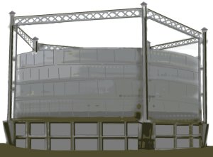
This tank has only five side masts, inset from these is a rail for the guide wheels on the tank sections. There is no cross bracing on the masts other than the trussing at the top. The tank sits in a metal caisson partially sunk into the ground which contains the water. Some tanks were rather more complex and represent something of a modelling challenge. The example shown below is quite a large town type in Salford near Manchester, in British N the diameter should be about eight inches but a seven inch diameter looks acceptable.
Fig ___ Gas holder
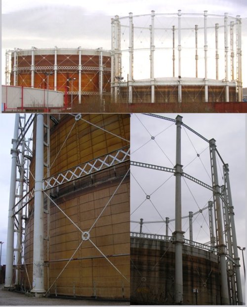
The capacity of this tank is 1.9 million cubic feet, or 53,704 cu m. As each section is lifted by the gas the weight and hence the pressure increases, with one section lifted the pressure is 10mb, with all four lifted it is 23mb. The base of the tank is set into a concrete base, when empty you can step on to the top of the tank, other tanks had a fixed base above ground (as shown on the spiral lift tank below).
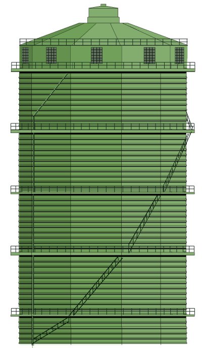
In 1888 a new design appeared which used spiral tracks on the tank sections, these tanks did not have the side mounted supports. The example shown is in Sale south of Manchester, again the diameter should be roughly eight inches in British N but six inches looks acceptable. Note how the side staircases are fixed, there is no inner handrail so as the tank sections move you can always step onto the walkway. The stairs are narrow, only perhaps fifteen inches wide. This tank holds 2 million cubic feet of gas (54,000 cu m) and has four sections or 'lifts' which rise up from the base. The base of the tank is set in a pit, presumably to contain the water if it leaked, this can be seen in the lower left of the photos below.
Fig ___ Spiral track gas holder
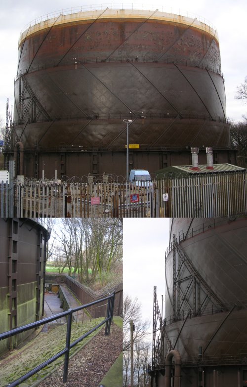
Note that on the 'spiral track' type tank the rails usually (but not always) run in alternate directions on each section. The access ladders, which are very narrow, perhaps 15 inches or 40cm, are supported on triangular frames mounted on top of the sliding sections and off-set round the tank so as the tank sections spiral up and down access to one ladder is not blocked by the ladder on the lower sections.
In the late 1920's an alternative kind of gas holder appeared which did not use the water seal, these consisted of a tall vertical tube with a close fitting piston inside. These 'dry' gas holders were always large, typically a third again as high as any adjacent telescopic types, and I was not able to get a decent photo of any before they were demolished. They were encased in very tall buildings which appear circular from a distance but which were actually multi-sided. The sides appear corrugated but in fact the ribs were widely spaced, however for an N Gauge model you can get away with using Slaters corrugated plastic card. There were access ladders on the sides as shown and often one or two pipes about a foot in diameter running down the side. There were usually windows set into the top section for maintenance workers.
Fig ___ 'Dry' storage gas holder
Even in British N the dry type tank which used to stand at Stockport would be eleven inches in diameter by eighteen inches high. Even with modellers licence to keep the look of the thing it would need to be a minimum seven inches in diameter by a foot high. This type of tank was a regular feature at larger steel works, they often had the name of the works painted on them in large white lettering.
The 'dry' type tanks (as I remember them) were usually painted green although one which remained in use in Salford near Manchester until 2002 was a light grey-green colour for the last few years. Both the earlier 'wet' types were usually painted green, some were painted light grey and a few were very dark, almost black.
the gas was often pumped into smaller gas holders in the chain of processes so the flow could be controlled, these were mainly of the multi-lift (masted or spiral) type. At a more rural gas works the gas holders would be proportionately smaller, you can get away with a couple of holders about three and a half inches in diameter for such a works.
Modelling these various tank designs is discussed later. The change to North Sea Gas in the 1970s did not make these gas holders totally redundant, they were used for storage and pressure control for the new service. They cost a lot to maintain however and by the late 1990s there were only about five hundred still in existence. The privatised gas distribution company Transco has invested in new pipeline technology which eliminates the need for these gas holders and they plan to demolish all of them by 2010. Some have been 'listed' for preservation as monuments but most will have be demolished in the first few years of the twenty first century.
From the tanks the gas was passed through cast iron pipes, coated with a black enamel material made by dissolving coal dust into coal tar, to the homes and factories. Difficulties in sealing lengths of pipe lead to quite frequent explosions in the streets due to gas leaks in the 1820's and early 1830's. The gas from the early works still contained a lot of impurities, it produced an unpleasant sulphurous smell and soot when it burned. By the 1850's the process was much better understood and the filtering had improved but no one has yet found a way to get all the smelly sulphur compounds out of coal gas. By this time people were making considerable use of the by-products extracted from the coal tar and from the gas itself. The hot smoke was first passed through a water or air cooled condenser which removes the oily coal tar. A pump called an exhauster then passes the gas to a filtering bed to remove the smelly hydrogen sulphide (which gave early gas supplies the smell of rotten eggs). The water and lime mix was replaced by a dry lime filter in the 1830's and this in turn was replaced by iron oxide filtering in the 1850's. The iron oxide was actually a mixture of iron oxide (rust) and wood shavings, called Iron Sponge or Iron Mass.
The gas is then bubbled through water to remove trace acids and nitrates, of which ammonia was the most valuable. Water will absorb over seven hundred times its own volume of ammonia and the resulting liquid was called Ammoniacal Liquor. There were still impurities in the gas, some of which were worth recovering. The larger works would often have a Benzol plant to extract a range of oily hydrocarbons. The benzol mixture from town gas works was of poor quality and was mainly used as an additive for petrol. The gas would then be dried and pumped via a meter into the gas holder.
The coal used in gas works was selected for its gas producing qualities, most was supplied as a rough mixture of small coals mixed with coal dust. The coke from the retorts was therefore usually small (two inch lumps down to dust), it was mostly just graded and sold locally. In the early days children with small hand carts hauled it away but by the early twentieth century it was being sold in sacks carted away on lorries resembling loads of coal. Some was also sold in bulk and shipped by the wagon load for use as a fuel in factories. Most gas works feature a large stockpile of coke, the bigger the works the larger this would be but for modelling purposes a scaled down representation is all that is required.
Coke weighs a lot less than coal and it was common practice to add 'coke rails' to the top of a standard railway mineral wagon to enable it to carry a full load (Peco offer a set of rails to suit their wagons). Specially built high-sided wagons were also produced for this trade and the pre-grouping Midland Railway standard design remained in service into the 1960's. On balance you would see roughly the same number of coke wagons in the gas works traffic as coal wagons (see Volume 1 Fig___).
The coke from a gas works consists of over 90% pure carbon and its porous structure allows it to burn rapidly. As most of the impurities have been removed it is 'smokeless' and much less smelly than coal, so the larger lumps were popular for domestic stoves.
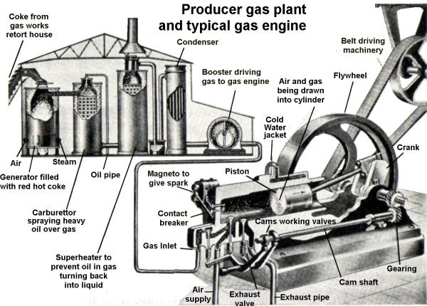
Up to the 1940's most gas works coke was sold to factories as fuel, some was burnt but more was used to make producer gas and water gas which could be piped through the factory wherever heat was required. In smaller works some of the coke was used as fuel to heat the retorts, often this was loaded directly from the retort using a simple wheeled chute. Coke firing remained the norm at existing small gas works but in the 1870's there was a shift to using producer gas, made on site from the coke, to heat the retorts. This requires another small building, with a chimney, to house the gas plant (see also Lineside Industries - Prototype industrial ancillary structures). This kind of works remained in use right to the end of coal gas as the small communities supplied from such works were the last to be changed over to North Sea Gas in the 1970's. The illustration below shows a 'carburrated water gas' (CWG) plant, a developed form of producer gas which uses superheated steam and an oil spray to add calorific value to the gas produced.
Fig ___ Producer gas plant
From the First World War up to the 1940's a lot of coke from gas works was used to make synthetic ammonia for fertiliser but this practice died out quickly in the 1950's as ammonia from oil refineries came on stream. Gas works coke was also used (with limestone) to make calcium carbide, used in the production of acetylene gas. Unfortunately gas works coke was not suitable for use in a blast furnace for iron or steel making as it is too soft but some was used in refining other metallic ores.
The used 'iron sponge' is called 'spent oxide', it is liable to spontaneous combustion if it comes into contact with air. To get the sulphur out air was admitted which reacted with the mixture to produce sulphur dioxide (the main use for which is the manufacture of sulphuric acid). At smaller works the spent oxide was taken away in sealed container to a separate works to have the sulphur removed but at the larger works the sulphur recovery was done on site. In a typical installation the iron tanks containing the oxide were mounted on a low raised platform. There would be several banks of filters and each in turn would be un-coupled from the gas lines and lowered to ground level. Air pipes and sulphur dioxide extraction pipes were coupled in place of the gas pipes and the air was admitted to start the process.
The ammoniacal liquor was decanted into holding tanks and either shipped out in tank wagons or, at a larger works, it could be further processed on site. Ammoniacal liquor when distilled with lime (delivered in sheeted or 'cottage topped' open wagons) and treated with sulphuric acid produces ammonium sulphate, a valuable fertiliser. The sulphuric acid could be made at the gas works as described above, additional supplies would be delivered in glass carboys or, from the 1930's, in de-mountable iron tanks. Ammonium sulphate is a white powdery substance, shipped out in sacks, the area where this stuff was handled would have a lot of white staining on the ground and on any loading bank or platform.
In smaller works the tar from the condensers was dumped into a pit to be decanted into wooden barrels and sold locally for use as a wood preservative. Larger works would have a raised tank for filling the barrels and might also ship the tar out in Graham Farish type tank wagons for further processing.
My local gas works at Altrincham owned some tanks which resemble the Graham Farish wagon, these were painted red with ALTRINCHAM GAS CO. in foot high lettering on the sides, the remainder of the information, 'Return to Altrincham C.L.C. and etc) was on a red painted cast plate mounted on the solebar. There is a photograph of an early wagon owned by this company in Bill Hudson's book Private Owner Wagons Volume One (see Bibliography). Do note however that this dates from the private ownership era, the Altrincham Gas Company was purchased outright by the corporation in 1872.
In the early days most tar was used for road surfacing, waterproofing felt for flat roofs and as a wood preservative. After the 1880's people started distilling the tar to extract a range of valuable chemicals. The processes involved favoured large installations and many tar distilling firms set up to process tar purchased from smaller gas works (see preceding section for information on coal tar distilleries). By the end of the century some larger works had their own tar distillery on site, invariably known locally as 'the chemical works'. The degree of processing varied from site to site and from a modelling perspective it is better to rely on a separate firm as this generates more interesting traffic.
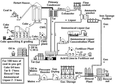
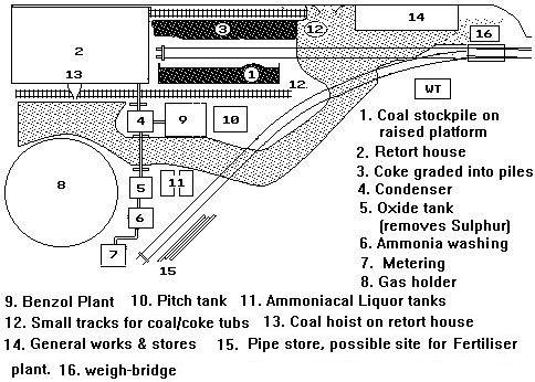
Flow diagrams for small medium and large gas works
Fig ___ Small Gas Works
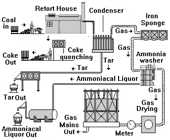
Fig ___ Medium Size Gas Works
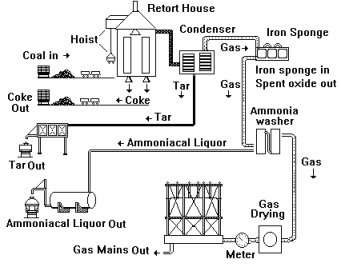
Fig ___ Large town gas works
Some works were very small indeed, virtually every town had a gas works and not all towns were large. At Seascale in Cumberland in 1939 the entire staff of the local gas works was one man, Mr. Lee, who also had to maintain the local gas meters and appliances. He bagged and carted the coke from the ovens for sale in the area and also sold barrels of unrefined coal tar. These small works continued in use right up to the change over to North Sea or Natural Gas, in fact the smaller establishments in remote towns were the last to go, outliving their larger more modern brethren. The last coal gas works in Britain was at Muirkirk in Ayrshire which closed in 1977 when the town was connected to the new gas grid.
The small town gas works at Fakenham, about thirty kilometers North West of Norwich in northern Norfolk, is now a listed ancient monument. There is a very nice little gas holder dating from the 1880's and a retort house dating from the 1840's. When it closed in 1965 the works was partially preserved as a museum, operated on a volunteer basis and normally only has open days on Thursdays during the summer months (May to early September). For further information on open days for the Fakenham Museum of Gas call: 01328 863 150 (Summer months and daytime only).
Gas works used coal in small sizes, typically 8 inches (400 mm) cube down to dust. This was often carted from the local railway yard in horse drawn carts but even some quite small gas works boasted a siding or two. At my local town gas works a street tramway was used with a gas works locomotive hauling coal wagons up the middle of the road from the station yard to the works.
In smaller gas works the coal was wheel barrowed or shifted in small hand-trammed tubs on a narrow gauge track way to the retort house. A man with a shovel would then throw the coal into the retort pipes. At smaller works the coke was handled using long handled shovels and rakes. It came out of the retorts red hot and was moved in slatted metal 'coke barrows' to the quenching hut. The cooled coke was then wheeled in the coke barrow to a stockpile.
Fig ___ Small retort house with barrow and rake
The many small to medium sized establishments represent a viable option for inclusion on a model railway and the books by Peter Denny on his Buckingham Great Central layout contain valuable drawings and photographs of his models. Mr. Denny also wrote a very detailed article in (I think) July 1989 Railway Modeller Magazine on the design of small and medium sized Gas Works which you may find being sold at a bookshop or model railway exhibition. If you belong to a modelling club this may well be in the club library.
There were always at least two banks of retorts, so that one could be maintained whilst the other maintained the supply. At smaller works the retort house would be at least the size of a large two-car domestic garage, with the area where the men worked having plenty of head room and usually some form of roof ventilator.
In the larger works narrow gauge tramways were used to move the coal from the stockpile in small wagons, several of these tramways used steam locomotives to haul the wagons.
By the end of the 19th century new gasworks had become generally quite extensive installations featuring the use of mechanical handling aids. The associated processing plant for the by-products would often be on the same site and the whole establishment might cover anything up to a couple of hundred acres. They were often connected to the main railway system by a series of exchange sidings serviced by the gas works internal locomotives. The exchange sidings, two or three tracks each capable of holding perhaps twenty wagons, could be arranged along the rear side of the main line, feeding the 'works' represented in low relief or even painted directly on the back scene.
Modelling a Gasworks
Ian Franz has sent in a scan from a school book published in 1949 which shows the various elements of a medium sized gas works. My drawings are based on photographs of the large Stockport works and the small works at Fakenham, the plant in Mr Franz's contribution is different. Click here to open this illustration in a new browser window, it is rotated to allow easier printing
The retort house at a small gas works was often surprisingly small, slightly larger than a domestic two-car garage and about one and a half stories tall with some roof ventilation. There would always be at least two banks of retorts but these were usually in the same building. The retort house at medium sized works would be a tall building, typically three or four stories high, with two or more chimneys. There would be few windows but plenty of ventilation in the form of louvered or unprotected openings in the upper walls and probably a louvered roof ventilator similar to that on the Peco engine shed kit.
The roof might well be asymmetric (one side larger than the other) as shown in Fig ___ (4) due to the inclined retorts and the hoist for the coal tubs would be prominent on the side.
In a very small early nineteenth century gasworks serving an isolated community the condenser might simply be a six or eight inch diameter copper pipe, mounted zig-zag fashion on the outside of the retort house. At such a small works the condensed liquid tar with all the other impurities still in it might simply be drained into pits to be sold as a wood preservative.
By the mid nineteenth century a fairly standard arrangement of air-cooled vertical pipes was used in smaller works. These pipes were about eight inches in diameter and stood roughly ten feet high. They had couplings on the tops to allow them to be washed through, and one method of making such a condenser is shown in Fig ___.
The condensers at a medium to large scale works would typically be water cooled affairs, the sketch below is based on the system at a large gas works (Stockport). In some locations the water cooled condensers were inside the main buildings or in separate, small but well ventilated, structures. In photographs I found of one medium sized gas works the condensers were small square buildings perhaps fifteen feet high with slatted sides and pipes for the gas and cooling water. These can be made using a length of square section wood perhaps 25 mm deep by 30mm high and 30 mm long, with razor saw cut slots at about 2mm intervals in the long sides. Cut lengths of printed brick paper about 8 mm wide and 30 mm high, fill the edges of the slots in the wood with a little Milliput and glue the brick paper onto the corners to form the supporting columns. Finally add a door to one end and gas pipes from coat hanger wire or something similar.
Fig ___ Tar Condensers
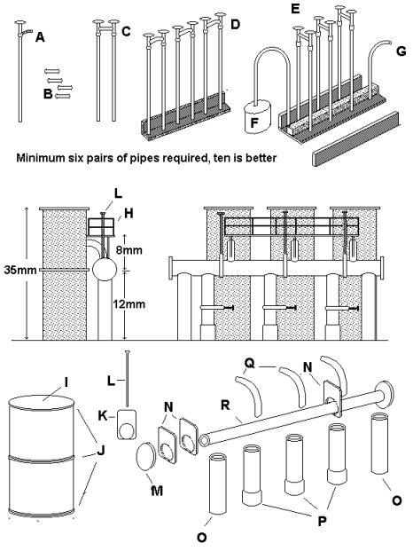
The sketch shows both air-cooled and water cooled condensers, the former would be seen at smaller works, the water cooled type is sketched from an example at a large town works. For the air-cooled type take a supply of one inch panel pins, the original pipes were about six to eight inches in diameter. Add a strip of paper about 1mm wide about 2mm from the top as shown (A). Now cut some lengths of any suitable 1mm diameter rod, plastic or wire depending on what you have available (B), all these must be close to the same length. Glue the short rods between pairs of the panel pins (C). The pipes might be arranged in a line (D) or in a double row (E). There will be a pipe leading to the tar tank, often through a raised metal man-hole size cover (F) and an inlet pipe (G), both of which should be no less than 1mm diameter rod or wire.
Glue the pairs to an L section support or to either side of a central support and fill between them with Milliput putty. The base of the pipes was often encased in an iron box. In some installations there was a low brick wall round this unit, in others it was open onto the yard area.
The water-cooled condenser could be simply a set of three or four 8mm diameter tubes with a 1mm and a 2mm diameter pipes feeding each top and bottom (the top 2mm pipe might come out through the top or from the side near the top). Gate valves to control the flow would normally be fitted as described below. The large water cooled condenser is based on the unit at Stockport. As drawn the system would work but I have simplified things somewhat to make modelling a more practical proposition.
The handrails (H) are from Plastruct glued to a 6mm wide strip of 1mm scribed plastic card to represent the walk-way. The raised spindles (L) connected to the gate valves (N) are track pins, the heads representing the hand wheels.
The main body of the unit (I) is a tube of between 8 and 10mm diameter, it is 35mm long with the end covered with a disk of 10 thou card or simply filled in with putty. The larger diameter pipework would be 2 or 3mm diameter and one option is to use old ball-point pen refills. These are made of quite a soft plastic and can have a length of brass wire inserted to help when making curved sections. You will need five lengths of the same pipe roughly 12mm long. The main horizontal pipe (R) is 30 to 35mm long and the vertical pipes beneath it are all 12 mm long. The three centre vertical pipes (P) should have a 2mm wide strip of paper wound round the base. Once the tube for the main pipework is selected and the diameter is known you can use a leather punch to make suitable holes in 20 thou card. Once the holes are made use a sharp knife to cut out the shape for the valve housing as shown (K). Three of these are threaded onto the horizontal top pipe (N) and three more are used for the three centre vertical pipes. Measure the distance between the valves and drill three holes in the walk-way to suit. The track pins pass down through these to the valves. If you feel up to it the gate valves on the vertical pipes can be controlled from the upper platform by using track pins passing down through the floor, this was the arrangement on the prototype but on the drawing I have shown hand wheels at ground level.
The platform is supported on struts from the pipework as shown, if you feel it would be easier you can support this on 1mm diameter rod reaching down to ground level. One end of the platform must have a length of brass signal ladder for access. The whole assembly was a dull silver colour with some staining and the bottom 2 or 3 mm of the vertical feed pipes at either end (O) should be painted black. You could use green as the base colour if you wished and a few streaks of 'rust' using an almost dry brush of 'track colour' would be appropriate.
The iron sponge was contained in air-tight rectangular iron tanks, one easy option for these is a model water tank mounted on the ground although this is a bit tall (the prototype was about three feet high). The tanks had a removable top so the spent oxide could be removed and although the iron sponge containers were usually covered they often the building had one or more walls missing, some were just a simple roof on metal supports. The Ratio corrugated iron roof unit would do for such a cover.
The ammonia washers at smaller works were often tall tubes perhaps three feet in diameter with gas and water pipes top and bottom. They were usually mounted outside and connected with gas pipes perhaps a foot to two foot in diameter and water pipes about three inches in diameter. Biro tube will serve for the gas pipe, soft iron 'florists wire' is suitable for the water pipes.
Fig ___ Iron oxide tanks and ammonia washers
The main body of the unit is a simple box, add strapping to the outside as shown using 10x20 thou strip or thin strips cut from masking tape. The tank and pipework was all green at the Stockport plant, you might paint the tank black to show up the pipework.
The liquor was stored in tanks, above or below ground, and it was usual to concentrate the ammonia to as much as 25% by volume before shipping it out or using it to make fertiliser on site. The production of fertiliser would involve quite a large building with good ventilation and a chimney or two.
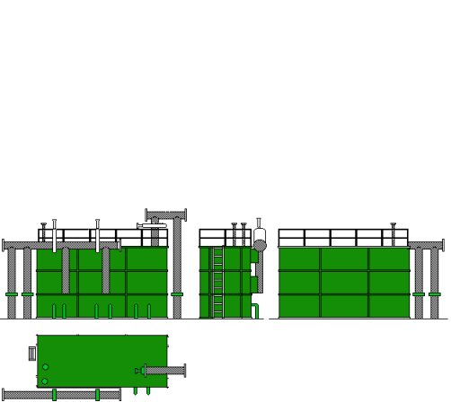
Fig ___ Ammonia concentration plant & fertiliser works
There was a lot of pipework in a gas works, in the larger works much of this was elevated and carried in gantries to allow road and rail vehicles to pass underneath. Adding such pipework helps identify the place and you can use the smallest Plastruct Fineline truss frames or even signal gantries to carry the pipes.
There would usually be a fairly large stores and workshop complex somewhere about the works. One area would be reserved for storing pipes, typically twenty feet long by four inches in diameter and black in colour. There was often a small crane in the pipe storage area for loading and unloading road vehicles.
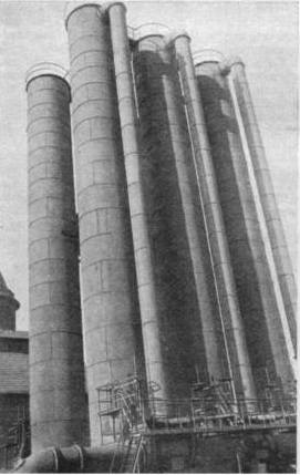
The Benzol plant was often in the open and resembled a miniature oil refinery. This is not actually difficult to model, although you may have to explain to visitors what it is supposed to be. The photograph below shows the fractionating columns used to recover the Benzole at a large gas works.
Fig ___ Benzol plant
In the 1950s and 60s (possibly earlier and later) there was a fleet of rail tanks operated in the rather plain livery of 'Benzole Producers Ltd' from many of the larger gas works sites. In the early 1950s their plain silver Class A tanks had either BENZOLE or BENZINE written in large lettering on the sides with the company name and 'home' depot details in the lower left of the tank in small lettering. Full details on these tanks can be found in Mr R. Tourret's book Petroleum rail tank wagons of Great Britain' - See bibliography for details.
Fig ___ Benzol Producers rail tanks

The gas holder itself represents the most difficult element to model, for one thing these tanks were often very big. In British N a large gas holder would be perhaps a foot in diameter and getting on for a foot or so high but as few people ever got very close to a gas holder you can reduce the size a lot a still keep the right general 'look' of the thing for modelling purposes. Fortunately not all gas holders where huge and the smaller kind were the last to go. For a smaller works serving a small town the minimum size for a tank would be about six inches in diameter by about six inches high.
You could add a tank or two painted on to the back-scene, but it looks a lot better if there is something actually there. One option is to build a half tank against the back scene or better yet build it into a corner where you cannot have any railway in any case. Piko offer a gasometer in their range (part number 60013), although it is rather small and of a somewhat continental appearance it would do for a small gas works. Very small gas holders are quite easy things to model, they might be used at a small works as the main holding tank or at a larger works for flow control. Fig ___ shows the small gas holder at Fakenham and a suggestion for modeling it using the cap from a tin of Jiff spray cleaning mouse. This is two and a half inches in diameter by two inches high so the proportions are about right. Do note that these aerosol can plastic tops are not cylindrical there is a very slight taper from the open end toward the top, but in this case we can make use of that feature.
Fig ___ Fakenham Gas Holder
To convert the tank into a gasometer you need to make the top domed and add something round the lower half to represent the water tank base. To dome the top pour in some boiling water and leave it on the draining board for about twenty seconds. This softens the plastic slightly. Tip out the water and holding the top in both hands use your thumbs inside to push the middle outwards. The required curve can be very slight but you will probably need to repeat this two or three times to get it right.
Fig ___ Modelling a Gas Holder
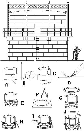
Now take some one inch brown paper masking tape and wind this round the lower part of the Jiff top (A), keep it tight at the bottom edge, do not smooth it down as you go. This is because of the taper of the top, smoothing the tape down results in lumps and folds of tape. Keep winding until you have built up about a millimetre of thickness. Cut three cocktail sticks in half and chamfer the cut ends as shown (B).
Use the tip of your modelling knife to ease the masking tape away from the plastic at the top and insert the cut down cocktail sticks. Adjust the position until all three pairs are arranged symmetrically round the sides (C). Now lay a strip of masking tape down on a smooth surface (I happened to have a cutting board but a china plate would do). Using a metal straight edge and a sharp knife cut strips 1mm or so wide from the tape (D). Lay these strips round the base of the tank on the existing masking tape base, this represents the horizontal frames. I suggest you lay one strip round the bottom edge, another round the top and two more in between. Cut some more strips and lay vertically these between the horizontal bands, you should cut them with your knife where they join and arrange them in a brickwork pattern as shown (E).
Now use a set of compasses to draw two circles on card, if you use plastic card for this you can use dividers and scribe round until you cut through the card. If using cardboard mark the rings and cut with a small, sharp, pair of scissors (F).
Offer the resulting ring up to the cocktail sticks and use a pencil to mark the ring where they fall. Use your modelling knife to make small nicks in the card so it will slip over the sticks and slide down onto the masking tape ring (G).
The access ladder is an N gauge signal ladder glued to the edge of the platform as shown (H).
To add the handrail I suggest you use OO scale etched brass signal ladders, curved to fit the outside of the ring and glued on edge. (I) Alternatively you can do what I did and add an inner handrail of fine wire glued to the cocktail sticks, Health and Safety would not appreciate such an arrangement but I suspect it was not as uncommon as you might think.
Finally you need to add the bracing to the top of the cocktail sticks, you could use etched brass N gauge signal ladders for this (it should be trussed as shown but laddering looks okay). Personally I just added another strip of the masking tape, 2mm wide, round the posts at the point where they start to taper. Paint the upper part of the tank, the cocktail sticks and the bracing between the posts green and the masking tape very dark green. The ladder leading to the platform can be light green or black, the handrails should be light green or light grey in colour. When the paint is dry give the lower section a dry-brush of dark grey and green to bring out the detail of the strips.
This represents the easiest way to obtain an acceptable result, you can use more care and more expensive materials to improve the model but as described it looks the part well enough and would stand comparison with most commercial models.
To model larger tanks one option is to use another tank kit basis, you need to select a model of about the right size for this. Vero, who operated from the former East Germany, used to offer an inexpensive gasometer in HO, the tank from which would give you a reasonable scale tank for an N/2mm scale model. You would need to add the supports and other details yourself. On the prototypes the smallest number of supports I have seen on a larger tank was five (at a gas works in Scotland), the trussing across the tops cut across the top of the tank and there were no trusses further down the tank.
Kibri offer a pair of oil storage tanks (part number B-7466) which can be used for the job. These are three inches or so in diameter by about three inches high, which is somewhat under-size but the end result is acceptable. The tanks are supplied with a spiral staircase up the outside, for a tank with side posts that goes into the 'bits box' as all you need is the tank body and top dome, for a spiral type tank you add the triangular supports. I would suggest the easiest type to model from these tanks would be a three-section spiral-tracked type, suitable for any period after 1888.
Again the lower sections can be made by winding masking tape round the tank, in this case the tank is in three sections so you need two strips of tape one twice the thickness of the other as shown in Fig ___. The spiral tracks can be represented by strips of microstrip (30x30 thou is about right) but this is difficult to glue to the tap, thin strips of post card would be easier to attach. Failing which you can use thread, having built up the telescoping sections measure the circumference of the tank and mark the top edge with five equally spaced points. Drill small holes through each of these points and drill another set of five equally spaced holes at the first joint, roughly in line with original set. Fine thread or preferably monofilament fishing line can then be passed through these holes as shown to suggest the inclined spiral track on the side of the tank. Repeat this with the middle section, keeping the angle of the lines about the same as the top section but inclined in the reverse direction. If using a snap-on aerosol cap for your tank gluing the thread to the tank is a problem (Uhu might work) but by passing them through holes you can secure them to the inside with Araldite and that will hold them tightly in place when it dries.
Fig ___ Modelling a telescopic gas holder
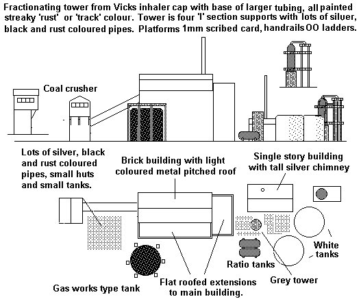
Modelling a big gas works is possible, the preferable location would be at one end of a baseboard where the gas holder can be represented by a simple quadrant section built into a corner.
At one of my local gas works (Stockport) the retorts and coke plant were all contained in a single large building which can be modelled in low relief. Sadly Stockport gas works was not rail connected, the coal was delivered by horse drawn cart, steam lorry and finally diesel tipper lorries and the coke was hauled away in similar vehicles. However for modelling purposes the arrangement at Stockport has several advantages.
The main building at Stockport, housing the retorts and coke plant, was a steel framed building with brick in-fill. The basic shell of the building was retained when the works changed from horizontal to inclined and finally to vertical retorts. The structure is interesting and serves well as the basis for a reduced size model. The coal was lifted by bucket chain conveyors to feed hoppers inside the building, these hoppers contained about 48 hours supply of coal. Similarly the coke was handled using conveyors and bucket-chain lifts feeding inclined tubular graders and thence storage hoppers inside the building. The coke was stockpiled outside in large heaps, but for modelling purposes this can be ignored. A coke bagging plant was included but for our purposes bulk loading of railway wagons is of more interest. A water-gas plant was also built-in to this structure, the gas was used for heating the retorts and topping up the coal gas as required.
Fig ___ Suggested large gas works main building
Large water-cooled condensers were used at all the local gas works and the tar was stored either in underground pits or in iron tanks. The ammoniacal liquor was concentrated in a small plant on the site, we can assume this is on the far side of the main building for modelling purposes, and stored in a fairly standard oil tank for bulk loading of tank wagons. The residual pitch from the tar pits would be pumped into a heated container for decanting into tank wagons.
At least one small oil tank is required as oil-mist was sprayed into the gas flowing into the mains to form an anti-corrosion coating on the inside of the pipes (it also removed some of the more troublesome impurities). This allows conventional class B oil tanks to be shunted into the works at intervals.
I have included a small gas holding tank of the type described above, the local works had such a tank for flow control purposes and it is so easy to model it is worth including.
The main gas holder would be more difficult to model, probably the easiest would be one of the warterless types built in the 1930's (see Fig ___ above) but a big telescopic tank with external frame helps set the scene.
Optional elements include the benzol plant and the fertiliser plant both of which generate traffic and ancillary elements such as the iron-sponge filter units (these were processed on-site at my local works so involve no additional traffic).
Fig ___ Suggested layout for a gas works
Any gas works would receive regular, typically daily, shipments of coal and occasional consignments of 'iron sponge' in drums, loads of pipes in open wagons and other equipment in vans. Many gas works used carburrated water gas to heat the retorts (see also Prototype industrial ancillary structures) and so would receive regular tank wagon loads of (petroleum) oil. Outgoing cargo would be wagon loads of coke, barrels or tank wagon loads of tar and possibly ammoniacal liquor, occasional wagon loads of spent oxide in drums and quantities of various 'distillates' drawn from the gas in manufacture. If the works is large enough to boast a small fertiliser plant you can justify colourful PO vans.
More recently there have been a number of attempts to obtain gas from coal in other ways. One which found favour in the UK was the German Lurgi process, in which powdered coal is heated and steam is blown through it to produce the gas. The process is similar to that for water gas but the chamber is pressurised and the yield contains a lot of methane and is usually referred to as Synthetic Natural Gas (SNG) to distinguish it from normal coal gas or 'town gas'. The last Lurgi SNG plant, in Scotland, closed in 1985.
Fig ___Sketch of a Lurgi Process plant in Scotland (1970's)
In the 1960's various ways were tried to produce something similar to coal gas using oil. Oil was cheap at the time and the resulting gas could be made without the poisonous carbon monoxide found in coal gas. Over two hundred plants were built round the country but they resembled oil refineries rather than gas works, the only real clue being the associated gas holders. Such a plant would require regular shipments of oil in tankers, they used a blend of fuels so you need a mix of class A and class B tank wagons. The 'works' consisted of modern concrete and pressed metal buildings, a lot of pipe work, several chimneys of the tall spiral finned type and several oil tanks. This is perhaps the easiest type of works to model. As with the coal burning plants these were all closed down by the end of the 1970's.
The change to North Sea Gas saw the introduction of a new type of gas holder designed to operate at high pressure. These pressure tanks were large, perhaps thirty feet (10m) in diameter with domed ends. They were mounted in banks as part of a high pressure gas distribution grid.
The nationalised gas industry was sold into private ownership in 1986. The distribution side of the business, being a national monopoly by its very nature, became a new company called Transco and the purchasers of the former Gas Boards act as customers who sell the gas to the consumers. In the late 1990s the business was further de-regulated allowing other companies to act as middle men between Transco and the consumer.
One odd point that came up when talking with a banker was that current banking practice will only tolerate a lag of three years before gaining a return on their investment. The early gas industry, competing with existing systems and requiring investment by consumers, seldom saw a return in less than five years (the first customer was often the local corporation street lighting and the gas was often supplied at cost as the advertising value and development of the mains supply was worth having). Hence, if the gas supply were being proposed today it would not receive the required funding and we would have to do without it. This three years limit has undoubtedly impacted British industry, whilst German and French engineering firms are booming supplying high tech equipment to the world British manufacturing is still contracting at a steady three percent per year. Perhaps more importantly it begs the question what options today, perhaps relating to matters such as clean drinking water, are not being pursued because of this arbitrary limitation.
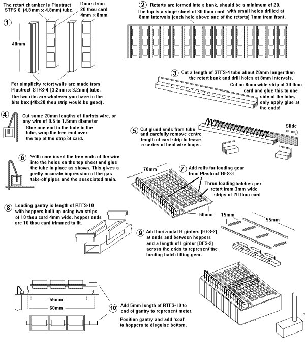
Coking and Smokeless fuel plants
Coke from gas works was unsuitable for making iron and steel and to meet the demand most steel works had their own internal plant which although working on the same principal as the gas works was built very differently.
Coke was originally made in simple beehive kilns (see Fig ___), and some was made in this way into the 1950's when the practice was ended by the clean air acts. By the 1850's an alternative method used long horizontal retorts forming a series of narrow slots, a system originally developed in Belgium, these did not become the norm in Britain until about the time of the First Word War. The walls of the retorts are made of fire clay and contain small tubes in which gas is burnt to heat the coke. A single retort is typically a couple of feet wide by perhaps fifty feet long and fifteen to twenty feet high. They are top-loaded and typically hold about fifty tons of coal at a single charging. These retorts are formed into banks of twenty to fifty and each in turn is filled, heated and discharged. The discharge is accomplished using a hydraulic ram, mounted in a building along the rear wall of the bank, and pushes the coke out through a hole at the opposite end.
The heat for the retort was originally provided by burning some of the coke and directing the hot gasses through the retort walls but by the time of the First World War the most common method was to use the coke to make water gas or producer gas and burn that inside the retort walls themselves (see Prototype industrial ancillary structures for details of the water gas plant). All the exhaust gasses from the heating of the retorts are taken to a single tall chimney and ranged along the top of the retort are the pipes for tapping off the oily smoke and tar fumes.
Fig ___ Modelling a Coke Oven
Most coking plants had a sloping bank at the discharge side of the ovens, the hot coke was pushed from the oven onto this slope where water was sprayed over the coke to cool it. The coke then had to be picked up and shifted to the grader and thence to the stockpile and wagon loading area.
There is a useful variation at the Moncton Gas and Chemical plant in which a special hopper wagon running on a track beside the ovens catches the coke as it is pushed out, the wagon is then moved under a water spray to cool the coke down and finally empties into an underground hopper feeding a conveyor belt.
This requires much less room and as such is an interesting option for a model railway layout.
Smokeless Fuel Plant
In the later 19th century research began on extracting more of the valuable by-products from coal by varying the temperature and pressure inside the retorts. By the early 20th century there were over a hundred methods used in various locations but two in particular proved commercially viable. The older is the Coalite process, which uses externally heated retorts similar to those used in gas making. The Rexco process is slightly different as it uses internally heated retorts, these two processes recover different quantities of the various distillates from the coal gas and produce large quantities of coke.
As coke has had the impurities removed it burns with a clean smokeless flame, making it popular for domestic fires. Unfortunately most coke is rather friable and so it was usual to grind it to a powder mix it with some of the pitch recovered from the coal and press the resulting mix into briquettes. These briquets are sold as 'Coalite' or 'Rexco' smokeless fuel.
Britain has put more effort than any other country into developing smokeless fuels from coal, they have been on the market since at least the 1920's. The main purpose of the above named plants is however the recovery of by-products, so you should look at having at least two benzol type plants as illustrated above under modelling gas works.
__________________
^
Go to top of page