Canals, Docks, Harbours and Ship Types
See also Appendix One - Canals, rivers and coastal shipping for more information on coastal shipping, river and canal barges (includes a description of standard markings and flags used) and Appendix One - Fishing boats and ports for more on the fishing industry and port facilities. Dock side cranes are discussed below but also see Wagon Loads & Materials Handling - Materials Handling - Hoists and Cranes and Materials Handling - Crane Hooks and Lifting Aids for more on cranes and cargo handling gear.
Canals
Canal/rail interchanges were not common, the two systems were more often than not in competition, but in the more industrialised areas the economic advantages were such as to promote their use. Birmingham was the hub of the British canal system, it has more miles of canal than Venice and boasted over two hundred canal rail interchange points, many involved in the coal trade. The last railway fed canal coal wharf closed in 1969, this was at Hawne in Birmingham. The Oxford Portland Cement Company was originally established close by a canal, with the coming of the railways a wharf was built at Bletchington where the bagged cement was transferred from barges to GWR freight trains until the works closed in 1928. The railway companies bought up several canal businesses and made some limited use of them. The LMS had quite a large fleet of canal boats in its livery and the Great Western Railway used canals to supply their sleeper depot outside London with wood and creosote (carried in tanker barges), the finished sleepers being shipped out on railway wagons.
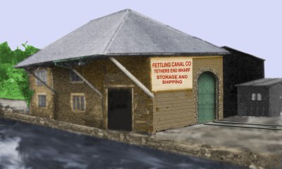
On a branch line you can add a small canal wharf, linking the branch to the waterways, and this does not require much in the way of space. The building below is based on a real canal warehouse although the prototype had no rail connection, the end wall being blank stone. Such a building has character and serves well in a corner location, perhaps served by a stub from the main canal, and would serve as a combined goods shed and canal interchange shed at a small country station.
Fig ___ Canal/Rail Goods Shed and Warehouse
Canals were cheaper than rail or road for bulk hauls of low value material such as coal and right up to the 1960's canal barges were loaded with coal hauled from the colliery by rail. Wigan Pier is in fact a wharf where wagons were tipped into coal barges, the new museum there has restored some of the tipper mechanisms. Coal handling on canal wharfs and river banks is more fully discussed below in the section on Docks.
Canal warehouses were often served by a short cut extending under the building, enabling loads to be lifted up inside. This can save you some space and adding a railway siding alongside the warehouse gives you an excuse for some canal modeling.
Fig ___ Canal/Rail Warehouse
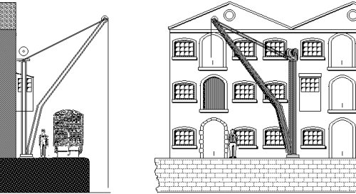
The sketch above is loosely based on a canal-only warehouse in Worksop on the Chesterfield Canal, I have added an hydraulic crane although the prototype had something very like a Midland Railway yard crane on the wharf itself.
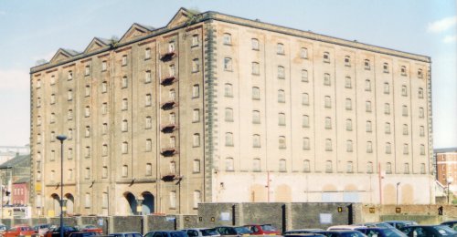
The more important canal terminals, inside the larger towns and cities, often had substantial warehousing, the example below was built on a canal basin in Manchester (it has since been converted into 'micro-flats' for young trendy types).
Fig ___ Typical large canal warehouse
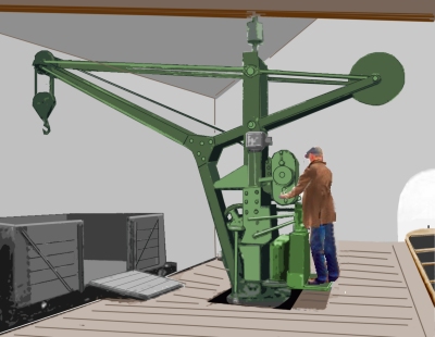
Most goods were man-handled on and off the barges, canal side cranes would have been mainly of the hand operated type, although powered cranes would sometimes be provided, mainly at warehouses. In the sketch above I have included a hydraulic crane, based on the original building in Worksop, note how this crane serves not only the railway but also both the upper and lower warehouse doors. The sketch below is an electric (possibly originally manual) crane traced from a photo taken inside a rail-canal warehouse. The barges enter the building via the opening on the right, the railway wagons on the left, note the water level in the canal is about the same as the level of the railway track, which could make modelling this building easier. The crane is sufficiently interesting to be worth including, visible through an open door.
Fig___ Cantilever electric crane used in a rail-canal transfer shed
For bulk discharging minerals such as coal the norm was men with wheelbarrows and even where cranes were provided grabs were rare, the coal being hand shovelled into bins for lifting out of the craft.
After the war some electricity power stations (such as the one in Trafford Park, Manchester) used a vacuum system to discharge coal from barges, but such complexity was rare and essentially Victorian methods were in regular use right up to the end of long haul narrow canal operations with the mineral cargoes being shovelled out by hand and moved by wheelbarrow to the stockpile.
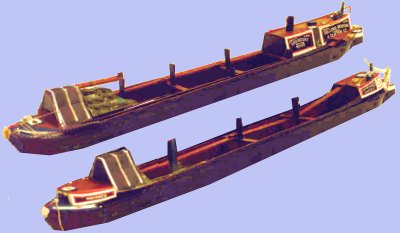
Horse towing of barges on inland waterways although increasingly rare was still seen into the mid 1950's and steam powered Weaver Flats were still trading (principally in the salt and chemical trades) into the 1960's but most craft used diesel engines from the 1920's. Note that on models of canal barges a chimney does not signify an engine, from the turn of the century railway competition meant that more 'bargees' lived on their boats and the stove required a chimney of some form. Steam powered barges generally had the engine mounted forward of the cabin with its own chimney. For intensive short-haul operations 'day boats' with no living accommodation continued to be used right up to the end of canal working in the 1960's and 70's.
Steam power was tried on the Sankey Canal in 1793 but developments were hampered by Watt's patents and steam did not become common until small and efficient engines were developed in the late nineteenth century. Adding a steam engine cost the boat about ten tons of cargo and of course fuel had to be paid for so even then horses remained the norm. The one advantage of the steam powered narrow boats however was that they could pull two unpowered 'butty boats' behind them.
Fig ___ Steam narrow boat and unpowered butty
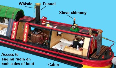
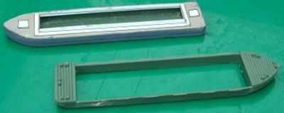
Note that on models of canal barges a chimney does not signify an engine, from the turn of the century railway competition meant that more 'bargees' lived on their boats and the stove required a chimney of some form. Steam powered barges generally had the engine mounted forward of the cabin with its own funnel as shown above. The cut-away shown below is from a photo taken at the Astle Park steam and vintage vehicle event, this was being sold (I believe) as a 'dolls house' (some detail has been removed to make the illustration more clear).
Fig ___ Cut-away of a steam narrow boat showing engine room
Steam tugs were used on some canals from the later nineteenth century. These vessels had a similar hull to the barges they towed although they were generally shorter. Canal steam tugs often had their bulwarks(the wall round the edge of the deck) cut down and replaced with stanchions and chains as this allowed the crew to cross to and from the barges with ease.
The Boat Museum, South Pier Road, Ellesmere Port, L65 4FW (Tel: 0151 355 5017) has a fascinating collection of material relating to inland waterways and when I visited the museum in the late 1980's the staff were exceptionally helpful.
Generally, for bulk trades, such as coal to power stations and the like, canals remained cheaper than railways right up to the end of their commercial operation. The narrow boats generally ceased trading in the early 1960's, although some regular traffic was still shipped on long hauls by narrow boat into the 1970's.
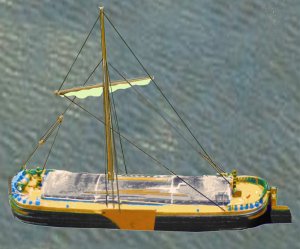
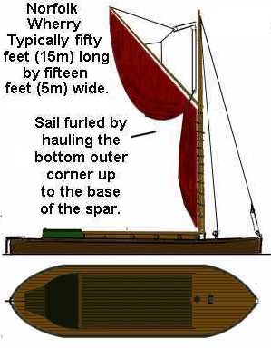
Low lying coastal areas with navigable rivers, such as are found on the East coasts, favoured sailing barges, each area having its preferred type such as the Norfolk Wherry (a model of which is about four inches long by one and a quarter inches wide), the Humber or Yorkshire Keel, the Sheffield cargo sailing barge (sixty one foot long by fifteen foot wide and fitted with a tall mast, and of course the Thames sailing barge. The example below is a model of the Humber keel, these square rigged vessels often had a second top sail above the main sail.
Fig ___ Humber Keel
Basically designed for hauling bulk loads of grain, coke, building materials, gravel, sand, cement and even horse manure, sailing barges found their way as far inland as Reading, and four Thames barges actually crossed the Atlantic.
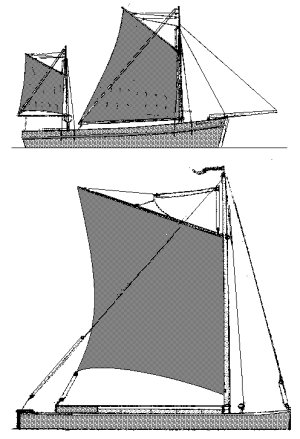
Another 'typical' small vessel, this time from the western coasts and rivers is the Tamar Barge, an example of which in restored condition is to be seen at Cotehele Quay, in Cornwall on the Cornish bank of the Tamar (this restored quay is unfortunately not a rail connected example).
Fig ___ Tamar Barge & Norfolk Wherry with sails set
Barge Models
The Langley range of kits includes a 'waterways set' (A18) containing a motor narrow boat and 'butty' (un-powered) narrow boat with a set of lock gates. They also offer separately a set of large canal lock gates (A18c) and small single gates suitable for the trans-pennine 'narrow' canals (A18d). These narrow boats generally ceased trading in the early 1960's, although some regular traffic was still shipped on long hauls by narrow boat into the 1970's. The two Langley boats (motor A18a and butty A18b) and the Fleetline 'coal barge' (BN-1) would serve for layouts set between the First World War and the early 1970's. Both Langley and Fleetline produce models of pleasure craft for narrow canals, suitable for layouts depicting the late 1950's to the present day.
The Airfix 'Pontoon Bridge' kit is useful, it includes a number of waterline model boats, although these do need cutting down as they are rather deep for N Gauge boats. I have had some success using these as 'lighters' (barges into which ships could discharge whilst waiting for a berth to become available, discussed below). The photo below shows one of these cut in half being converted into two barges that might be seen on a river of broad canal.
Modelling lighters
These represent a 'barge' type of lighter, in larger ports lighters tended to be very big and had a distinctive cut-away to the bows and stern, discussed in more detail below (see also Appendix One - Canals, rivers and coastal shipping).
There are European barges available from some continental firms, notably from Noch (discussed below) but these are rather big for a British setting. Noch offer a dumb (unpowered) barge in their OO range, this is acceptable for a British harbour lighter in OO but this scales out very large indeed in British N. For a British harbour lighter (see also Appendix One - Canals, rivers and coastal shipping).
Docks
Docks offer considerable scope for unusual loads, the possibilities for traffic in such an area are virtually unlimited. Larger docks were all rail connected and many had their own internal user rolling stock and engines. Docks are often discounted on the basis that they require rather a lot of empty space for the docks themselves but this is not really true.
The curves in dock railway tracks are among the tightest found anywhere which means one can squeeze quite a lot into a small space. As the track is inset we can use the Peco `Crazy track' points intended for narrow gauge layouts. These have a nominal radius of 12 inches and come with live frogs, offering better running than the 9 inch radius Set-track points. I believe the new short radius 'finescale' points also offer a twelve inch radius curve but the advantage of the fine appearance is off-set by the fact that in-setting the track is more difficult.
Railway lines laid into proper dock areas would be inset, that is the top of the rail would be level with the surrounding ground. This was commonly achieved by laying a 'check rail' (a second rail laid inside the running rail, as seen on 'points' or 'turnouts') and filling the space between these with cobbles, stone blocks, or later concrete, although the concrete method made track maintenance difficult. In model form this can be represented by building up the surrounding ground level close to the top of the rails and by filling the space between the rails with plaster of Paris and scribing to represent the blocks, you could cut up embossed card to fit but this would be more difficult. In general the points are not in-filled in model form, the amount of swing in the wing rails (the sections of track which move) being rather greater in N gauge than on the real thing.
Dock railway lines were not a constant hive of activity, for safety reasons shunting usually only took place at set times. In Manchester for example the quays were shunted twice a day, between 12.30 and 1.30 in the afternoon and between 5.30 and 6.30 in the evening. However if a rake of wagons was filled a special run would be made to clear them and bring in some empties.
Privately owned dock loco's operating outside the dock company property would often be 'tram' type loco's, which had condensing gear so they did not pump out much steam and side skirts to hide the pistons, coupling rods etc. (which it was thought would frighten the horses). Where locomotives ran along public roads the rules required a man with a red flag to walk ahead of the locomotive. Often the man stood on the foot rest at the foot of the locomotive, only dismounting when the line actually crossed a road.
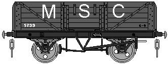
The dock companies often owned quite a number of wagons and vans, usually painted dull grey with the dock owning company initials on the side in white typically eighteen inches high. In Manchester the railway was operated by the Manchester Ship Canal company (and hence marked MSC) whilst in London, after 1908, it was under the Port of London Authority (marked PLA). The trade at the docks determined the type of wagons used, standard five plank opens were generally useful, coal wagons were used for distributing fuel within the docks area and ports handling a lot of timber or steel would have single bolster wagons and six wheeled or bogie bolster wagons. London had quite a lot of meat traffic and boasted a fleet of refrigerated meat vans and (by the late 1940's) refrigerated meat containers on flat wagons. On larger dock railways such as those in London and Manchester brake vans were required, usually these were bought in from main-line companies, the Manchester Ship Canal used a number of GWR toad brake vans (the GWR had a line which reached up to Birkenhead).
Manchester Ship Canal open wagon
Early docks were simply reinforced sections of river bank and riverside berths have remained in use ever since. Older docks serving small riverside towns were often not walled-in but formed a street along the river bank. The quay area, often cobbled, was backed by a row of warehouses and offices. An example of this can be see in Lancaster, the old warehouses have now been converted into accommodation but quite a lot of the old fittings are still present on the quay. Those who find their way to Pendon should take a good look at Madderport on J. H. Ahern's 'Madder Valley' layout which represents a smaller coastal town.
The enclosed dock, with a wall all the way round the dock area, had the advantage of reducing pilferage but is a more recent innovation, dating from the end of the eighteenth century.
Wharfs and quays are basically the same thing, a reinforced section of river bank where ships can be secured, wharfs are usually wooden, quays are faced with stone, both usually lean back against the bank to resist the pressure of the earth. If the landing place juts out from the bank it is called a pier or jetty. Isolated platforms used for tying ships up safely are called 'dolphins'.
There are a few points to note about the quay walls and general dock fittings. The quays themselves would have a solid surface, often cobbles (which offered a better 'grip' for horses), for which N gauge cobble sheet is available from Faller. Alternatively OO gauge embossed brick plasticard can be used, it is a little over-scale but looks reasonable. There is a picture of Southampton docks taken in 1900 in Southern Wagons Volume Two (see Bibliography), which shows what appears to be a tarred macadam surface on the quay and with the rail track set into the surface.
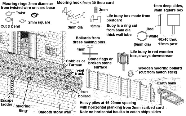
The quay wall in older docks would be made from stone blocks, or earth faced with timber with heavy wooden piles to hold it back. These can be represented in N using embossed or printed stone (the latter being preferable, dock walls were smooth to avoid catching the ships side as the water level rose and fell) or for the wooden type a facing of scribed card with match sticks set at intervals along it.
Fig ___ Section of stone quay wall on a river (the tide is out)
Note there should be NO horizontal balks of timber as are sometimes seen modelled, this would be dangerous as the ships side might catch on these as it rose and fell with the tide. Having said which you occasionally see what appear to be horizontal baulks on old photographs, in actual fact the verticals extend some way in front of the horizontal timber, preventing the ships side from being snagged.
Fig ___ Stone quay wall with timber baulks at a wood yard (the tide is out)
The sketch also shows how to avoid cutting a ship model down to waterline, simply have it on a river berth when the tide is out. On some quays they had a heavy iron or timber grid, timbers about a foot square with a length or two running parallel to the quay wall and several extending outward at right angles from the quay and resting on these longitudinal's. Where these were available the flat bottomed river craft could settle as the tide went out, keeping them level for loading and preventing them bedding down into the mud.
In docks on river banks the quay was often a wooden structure built on piles extending out over the bank. Poured concrete was used for dock walls from the 1880's but this would only have been used in more affluent docks and harbours.
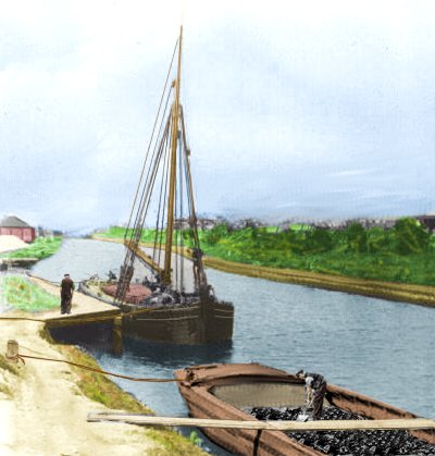
The scene below is based on a photo of the Runcorn canal, taken in about 1900. The sailing barge is moored to a small jetty but the horse drawn barge is alongside the bank with only a plank for access. Note that the plank extends right across the hold, so it is supported at the barge end, otherwise it would bend down or possibly even tip up when the man with the wheelbarrow reached the end.
Fig ___ Typical scene on a canal
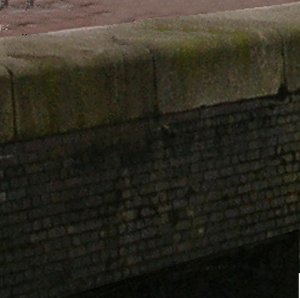
Bricks have also been used for facing quay walls, however I suspect this was mainly confined to enclosed docks rather than river berths or open harbours. The example below was photographed in the old Ontario Dock in Manchester.
Fig ___ Section of brick faced quay wall
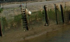
In enclosed docks or on river side docks where the quay was long it was common practice to have a ladder or flight of steps set in to a bay on the dock side. This allowed access to small boats at low tide but more importantly it allowed people who fell in to climb ashore. Where horses were regularly used the dock sometimes had a sloping ramp down to the water for the same purpose but these were less common.
On the quay itself you need somewhere to tie up your ships, on older quays they used iron rings anything from six inches to a foot or more in diameter mounted on the dock side. These are technically a kind of 'cleat' and they could hold a small sailing craft or barge safely but they would be too light to take the loads of a steam coaster.
To hold larger vessels you need a bollard, which is some form of post, usually with a flared top to hold the rope securely in place. In some places heavy timber beams were set into the quay with perhaps two feet showing above ground level and in the eighteenth century several docks had old cannon barrels buried muzzle downwards into the dock with about three foot sticking up.
By the eighteenth century cast iron bollards had appeared, often these were hollow castings but in later years the centre was filled with concrete. For N gauge layouts a simple expedient is to use dress maker pins cut down so that about three millimeters will be left showing above the surface. The head of the pin serves to represent the flared top of the bollard, if the head is a little on the large side add a little strip of cigarette paper wound round the pin itself to thicken the shaft.
Since the war ports handling larger ships have used a system of quick release hooks in place of the bollards, this is basically a labour saving device.
Fig ___ Quays & Wharfs Fixtures & Fittings
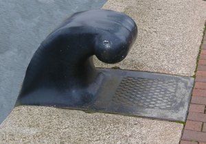
Set into the stone topping of the quays at Manchester are large iron bollards used for tying ships. This design dates back to the early 1930s but became common in the 1940s onwards.
Fig ___ Iron bollard set into quay wall
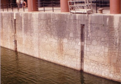
You may see large square logs lying alongside the quay floating in the water, these were to protect the quay from damage by the ship, and visa versa. These timbers were free to float up and down, often running on lengths of chain inset into the dock wall (these chains are still to be seen at the Albert Dock complex in Liverpool).
Fig ___ Liverpool dock quay wall with inset chains
A lot of cargo was unloaded from ships anchored in the river onto large barges or 'lighters' which were then towed into smaller basins for unloading. These lighters, which remained a feature of some docks (notably in London) into the 1960's, are not too difficult to model. There are some continental models available of the modern large river barges which can be pressed into service as discussed below, but these are really too large.
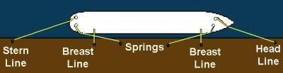
Ships and barges are NOT secured to the quay with chains they are secured with ropes which have a loop spliced into the end. Older ropes made of Manila or hemp fibres were brown in colour, modern ropes are often made of man-made fibre and will be light grey or even orange in colour. Steel wire ropes are sometimes used as well as the fibre types but wire ropes are heavy and difficult to haul ashore so some ports do not accept them.
A minimum number of lines for a small coaster would be four ropes, two from each end, one leading away from the ship and up the quay (head and stern lines) and one leading right ashore (breast lines). Anything larger would also have 'springs', which lead back towards the middle of the ship, often crossing each other. Springs are essential for all craft in a tidal or river berth.
Fig ___ Tying up a ship safely
Conventional ferries offered the only means of accessing the continent prior to the development of air travel and railway companies built extensions to feed the docks at which the steam powered high speed 'packet boats' called. In 1930 the Southern Railway converted an ex Royal Navy mine-sweeper to carry motor cars, these had to be lifted on and off by crane at Dover but could be driven over a stern ramp at Calais. Most international sea trade was carried in conventional multi-purpose or 'break-bulk' cargo ships which berthed at docks on the coasts and on the larger rivers.
In the mid eighteenth century someone came up with the idea of the 'tidal dock', an enclosed area of water connected to the river via a lock gate. The ships would enter the dock at high tide and the gates would be closed, this kept the water level in the dock as deep as possible. St Katherine's Dock in London and the Liverpool Albert Docks Museum are good examples of enclosed tidal docks.
Dock side warehouses on small riverside berths tended to be simple, often wooden, shed type buildings. The enclosed docks in river estuaries used similar buildings but these were commonly built of iron (metal frames with corrugated iron cladding). The new docks near the mouth of the Thames at Tilbury, built on a swamp and so unsuitable for extensive warehousing, featured relatively low structures of necessity.
Some enclosed docks were however built in cities (London & Manchester for example) and here providing storage space was an attractive proposition. Hence in the inner-city docks the dock-side warehouses were often multi-story brick buildings. The ground floor would be used for simple transfer to and from ships and road or rail vehicles whilst the upper levels provided warehousing space. The upper levels would be equipped with doorways allowing the cranes to pass the goods directly to the required floor of the building.
In ports where there were regular imports there would be a customs and excise 'bonded' warehouse in which dutiable goods were held until the tax was paid. Examples of dutiable cargo include wine and spirits, perfumes, tobacco, tea and silk.
Dock Cranes
People consider dock cranes to be a problem, and the modern type with its tall tower and lightweight construction would be difficult to produce convincingly. Not all docks used their own cranes of course, in smaller ports the ships would use their own derricks or deck mounted cranes. Cranes of various kinds have been fitted to ships since the 1960's but as already mentioned for general cargo work the traditional ships 'derrick' is better.
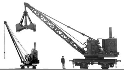
Docks used every type of crane available, including man-powered, hydraulic, steam and electric types. Small hand powered and steam rail mounted cranes were used for quays with no fixed cranes, they cam in handy for unloading barges or small coastal craft and for moving larger items about the dock area. If using a steam crane, such as the one in Liverpool's Albert Dock Museum, don't forget the coal bunker somewhere nearby.
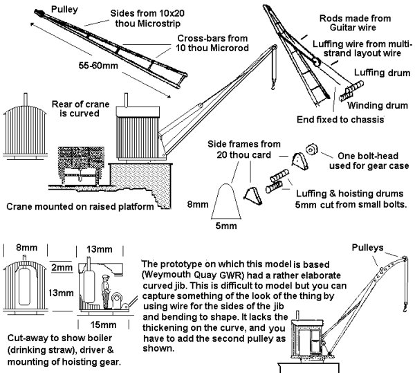
Weymouth Quay (served by the GWR) had in interesting arrangement where the quay was built up to form a platform along the dock edge which allowed goods to be easily loaded into vans. There were a number of small cranes mounted on this platform and this arrangement makes a pleasantly different model. Each year this small port handled about ten thousand tons of early potatoes and about twelve thousand tons of tomatoes all being imported from the Channel Islands.
Fig ___ Small steam cranes
The larger quay-side crane was generally a quick acting machine, generally with quite a small capacity (men were used to load up the crane and this restricted the advantages of larger equipment).
General purpose dock cranes, either electric or hydraulic, were originally standardised to handle 30 cwt. Some larger steam cranes were rated at two or three tons. A standard feature was level luffing, which meant the load stayed at the same height as the jib was raised or lowered. There were various methods used to achieve this, most subject to patents, however there was a series of articles in The Engineer magazine dated Aug 26th and Sept 2nd of 1927 which discussed these in considerable detail.
Most dock cranes built up to the 1930's could reach out about thirty feet from the quay wall. As ship size increased in the 1940's this increased to fifty feet and by the 1960's a reach of ninety feet was not uncommon. For modelling purposes we can reduce the length of the jib quite a lot whilst still retaining the general look of the prototype which makes for a more robust model.
More modern tall dock cranes appeared in the 1930's, most of these were electrically operated and most could safely lift up to three tons, although they were still loaded up by hand so except when lifting large single items the typical load was a lot less. In the 60's five ton cranes started to become more common but soon after this the container appeared and by the mid 1970's the general purpose cargo ship was becoming rare.
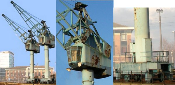
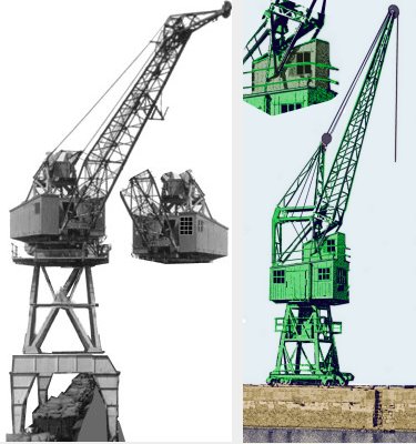
The examples shown below are preserved in the former docks at Manchester, an area now redeveloped as offices. These have comparatively short jibs as the size of ship using the port was limited by the size of the locks (most were in the 1-2 thousand ton range). Quayside rail mounted cranes of this type would serve for layouts set between about 1955 and the present day.
Fig ___ Manchester docks electric cranes
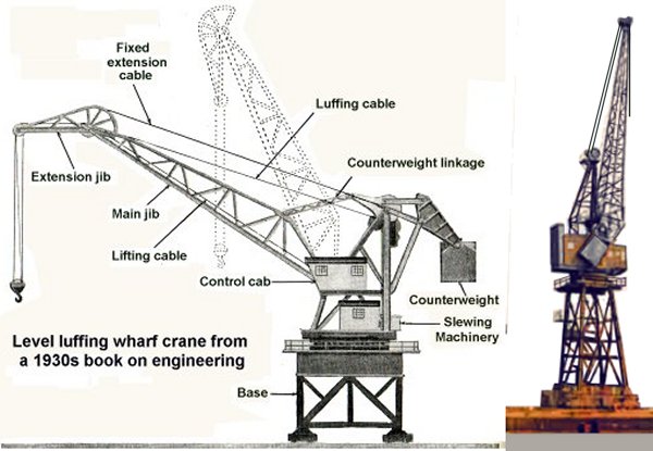
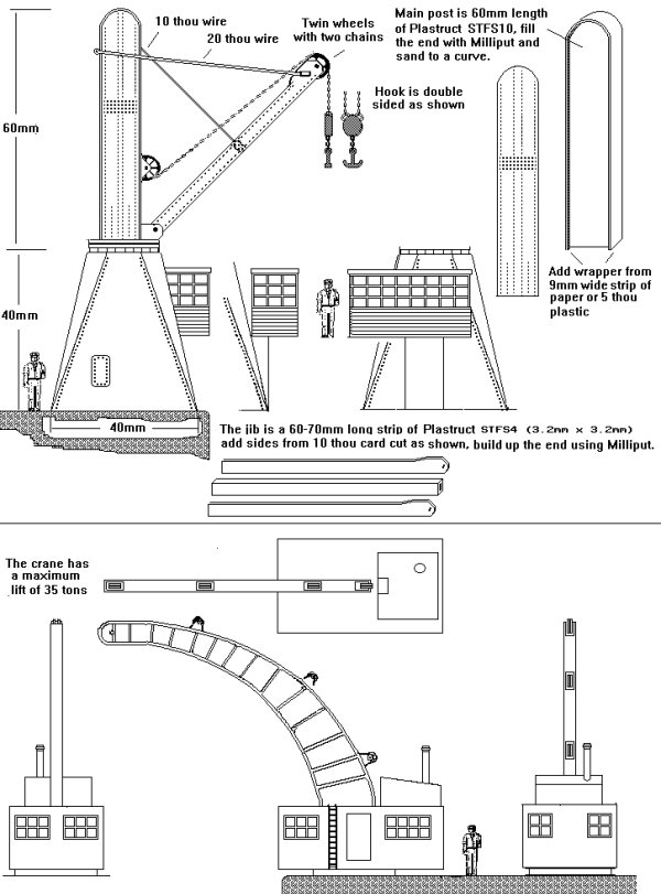
The sketch below shows a large wharf crane with something called a 'horses head' level luffing gear which was common on larger dockside cranes. See also the section on Wagon Loads and Materials Handling - Lifts, hoists and cranes'. The example shown (scanned from a 1930s book on engineering) is a big crane, the only times I have seen cranes of this size has been in dry docks. The example on the right is closer to those I remember from my own time at sea, these had the level luffing gear working onto the gearing of the cables. A large crane such as this would serve in a major docks from the 1930s to the present day and to model these in N Gauge the LNER lattice mast available from Ratio in their OO signals range makes a good starting point. For the base you can use Plastruct or you can cast about for kits that can be bashed, for example a water tower on tubular metal supports can be effectively cut down to suit, adding the side frames and wheels gives ample clearance for wagons passing underneath. A crane with a long jib such as shown would be seen on a river berth, it allowed the crane to reach over a lighter or two. Many quayside cranes had shorter jibs, those in an enclosed dock were usually much shorter (see the photos of the Manchester docks cranes below) but the tall crane with its long jib is very suggestive of a quayside.
Fig ___ Electric dock crane with level luffing using horses head extension
The larger cranes usually had the cab in the centre as shown above right, with the jib split and running to counterweights on either side of the cab (the crane driver must be able to see the load). I have had success using the Ratio OO scale LNER lattice signal masts for crane jibs in N but these cannot be used for this type of crane as the mast requires considerable widening at the base. One alternative as used on real dock cranes is to offset the cab to one side as shown below left. Another alternative, if using a signal post, is to mount the jib on top of the crane, the example below right (based on one in Bristol docks) has this arrangement with a small 'cab' on which the jib is mounted set above the main driving cab.
Fig ___ Electric dock cranes with offset cab (left) top hinged (right)
From the turn of the century it was standard practice to write the maximum safe load for the crane on the sides of the jib.
XXXX When was the SWL abbreviation introduced?
One space-saving arrangement used in real life had an overhead gantry supported at the landward end by a rail set on the roof of the storage sheds, technically this is called a 'half portal crane' (a full portal type has both rails on the quay). Fig ___ shows such a design based on two electric cranes built by Stothert & Pitt Ltd. and installed at Southampton in 1893. These were I believe the first electric dock cranes in Britain and I understand at least one survived until about 1953. This gantry arrangement was not uncommon and in the 1980's there were essentially similar electric cranes in use in Bombay.
Fig ___ Electric dock cranes
The drawing of the Southampton crane is not completely accurate, the originals had curved box section construction for the supporting gantry which would be difficult to model, the arrangement shown is intended to be an easier alternative. A picture of the original cranes will be found in the book 'Southern Wagons Vol.2' (see Bibliography) if you wish to make a true replica.
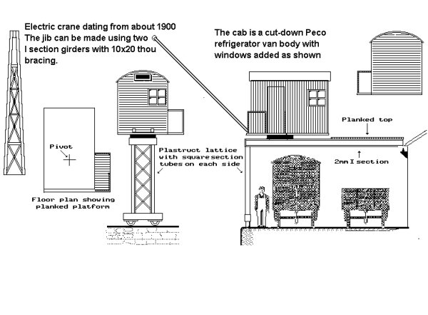
The suggested basis for the crane cab is a cut-down Peco refrigerator van body, this as a bit wide bit saves you having to make the curved roof. Cut the roof and body down to leave both doors in place and add a new 'driving' end from scribed card with a section of 'Downsglaze' signal box window off-set to one side and an aperture for the cables in the upper centre.
The gantry spanned two tracks and on the original there was a space about one track width between these, this additional space is omitted on the drawing to save space on the layout, there were quays with tracks arranged in this way.
Pola offer a 'mobile crane' as a kit (reference number XXX), unfortunately this features a fixed jib arrangement which although not uncommon in factories is unusual on such a modern looking crane when used on a dock side. John Ahern's famous Madder Valley layout had a similar crane in his Madderport docks but I have not yet traced any photographs of such fixed jib cranes in any British docks. The prototype of Mr Ahern's crane may have been a type used for hoisting coal wagons over a ship or barge, lowering them down and tipping them into the hold (this reduces breakage of the coal). One option is to replace the jib with a Ratio 'OO' scale LNER lattice signal mast (or an etched type if you have one to hand). This would be pleasantly intricate and reflects more closely the 'spidery' appearance typical of dock side cranes.
The base of the Pola crane is a bit large for the crane itself but it can be cut down, and if you are doing that anyway you might consider converting it to the building-supported design. This leaves you with one set of spare legs but a similar stationary crane is also available (catalogue number 248) which could be used to make a second crane. Personally I feel it is easier to build them from scratch as shown in the sketches.
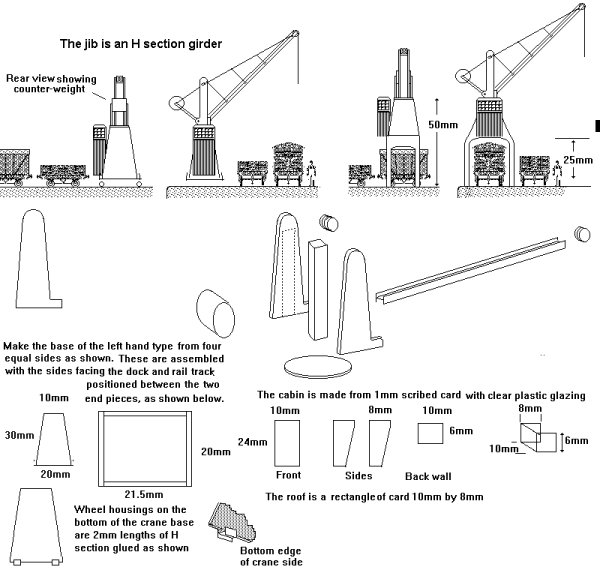
The sketch below shows two variants on a standard design of hydraulically powered crane used in docks throughout Britain and abroad. Both have a fixed jib mounted on a rotating base on top of a simple tapered base with a cab fixed to one side.
These were both sketched from 1930's photographs of Penarth docks in Wales. Note the drum shaped counter-weight on hinged arms which could be lowered to balance heavy loads.
Fig ___ Hydraulic dock cranes
Specialised facilities existing at various ports, the GWR served ports handling Channel Islands fruit and vegetable traffic, the quay-side was raised to form a loading bank with the rail tracks on the landward side. Small steam cranes were mounted at intervals on the bank to assist the unloading of the ships.
Where the quay was narrow a simple hydraulic crane might be mounted on the outside wall of the warehouse.
The hydraulic crane used water from a tall tower to operate rams linked to pulley sets to amplify the movement and so was usually a fixed item, although having said this there were several docks where these were moved along the quay on rails and sections of pipe coupled together to supply the water were laid along the quay.
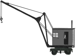
Not all dock cranes were large and complicated, the sketch below shows a simple type of electrically powered crane dating from about 1910. This was a fixed crane the original was on a quay on the Rochdale canal used to unload bales of cotton from large barges and lighters towed by steam tug from Manchester docks.
Similar cranes were also used in docks serving coastal craft, a steam powered machine of essentially similar appearance but with a heavy square section wooden jib was used at a dock in Wales to hoist loaded coal wagon over the holds of ships and tip them.
Where regular heavy loads were anticipated a large fixed crane or two might appear. The large crane shown below was sketched from a photograph of the GWR's London Brentfod Dock in the 1920's found in Janet Russel's book GWR Company Servants.
The design is essentially similar to the mobile types shown above but this crane is crane is anchored to the dock and so does not require the counter-weight. There were two cranes at Brentford, the second was basically the same but had a heavier jib and a pulley type heavy-lift hook. They were used for off-loading 'lighters' (a kind of large barge) which had taken on cargo from a ship at anchor in the river.
Even in sailing ship days a larger vessel alongside the quay could be several feet higher than the quay side. The curved jib on the Fairbairn crane was designed to reach up and over the side of ships moored alongside. An example of the Fairbairn type, built by Stothert & Pitt in 1876, still exists at the Princes Wharf Museum in Bristol.
Fig ___ Large hydraulic crane and Fairbairn crane
The problem of reaching over ships sides generally lead to tall cranes, however there were alternatives, the example below is sketched from a small self propelled steam crane in use on Fleetwood Docks. The jib is arranged as a dog-leg, suitably reinforced, there were several such cranes at Fleetwood and presumably similar cranes would be seen in other docks where the quay was narrow.
Fig ___ Quayside mobile steam crane
Docks - Cargo handling
NB see also the separate section on Wagon Loads & Materials Handling for more detail on equipment used in general cargo handling
Until fairly recent times the cargo had to be man-handled at several points on its journey, so shippers had to break down the loads in to suitable parcels. A standard item of ships and docks equipment was the cargo net, a square rope net about 10 foot to a side with a mesh about 9 inches square and with loops on the corners for slipping over the crane hook.
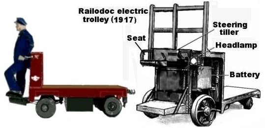
From the early 1920's docks, such as Liverpool and London, had large numbers of small electric run-about trolleys, these were about 7 foot long and 4 foot wide, running on 18 inch diameter wheels with the decking about 20 inches off the floor. These had a small platform on one end where the driver controlled the vehicle using small levers, there was usually a bulkhead or frame to protect the driver if the load shifted. Very similar types of run-about are a feature of large railways stations, and models were offered by most model manufacturers in the 1950's.
Fig ___ Run-about trolleys
A lot of goods were man-handled about the quay side and one small detail worth considering is a railway wagon with its side door dropped onto a barrel and a plank laid against the edge of the door to give access to a man on foot or a wheelbarrow.
Cattle were taken by rail to some docks specialising in this traffic. These had extensive pens which would require considerable room, even in N gauge.
Chilled meat was carried in ships from the 1900's, if you want to model these cut a model cow into right and left halves, cut off the head and legs just below the body and paint them white. These were (very) solid and a man can lift one at a time. To lift them from the hold of the ship they were generally laid on a wooden frame, which itself was in the centre of a cargo net. The railway companies used refrigerated and insulated vans and containers with hooks provided inside for these 'sides' of meat to hang on.
Butter has been shipped as a frozen cargo on ships since the turn of the century. The butter was shipped wrapped, in cartons, which often had light wooden battens attached to them for strength.
A lot of odd materials were shipped by sea, Britain at one time imported large quantities of dried dog droppings from Persia, this material being used for its high urea content in the preparation of leather (removing the hair from hides). These days synthetic Urea is shipped in place of the dog droppings, it is a white powder shipped in 80-100 lb bags or as 'prills' (small pellets) in covered hopper waggons, it is also sometimes shipped dissolved in water in standard steel drums. Urea, or carbamide, was and remains an important chemical, it was the first organic chemical to be synthesized (by Wohler in 1824) and it forms the basis for urea-formaldehyde resin from which the first plastics to be available in white, pastel and colours were produced.
The arrival of the 'Unit Load' concept in the 1950's produced the container and the pallet. The former can be lifted on and off ships using standard cranes (fitted with lifting frames) in smaller ports, but it is more usual to use specialised berths equipped with large gantry cranes (see Fig ___). Ships carrying containers range from large purpose built types (basically not a practical modelling prospect), right down to very small vessels, which might be converted from the Shell Welder tanker kit as discussed below.
The wooden pallet produced ships with side doors and ramps to permit fork-lift trucks to load and discharge them. Again these purpose built ships are not really viable for modelling, however palletised loads were, and are, carried in general cargo vessels and so would feature in a modern (post war) docks scene.
Docks - Coal handling
A lot of coal was shipped by sea, both exports and UK to UK movements, and colliers are an example of the specialised ship relying on shore gear to load and discharge them. One small point to note is that logically you would not have facilities to load coal into ships in the same port as equipment to land coal. The areas and chief ports associated with coal exports are illustrated in the map of the UK coal fields shown in Fig ___.
Coal was shipped in considerable quantities, justifying extensive dock installations devoted to nothing else, which tended to be vast sprawling affairs. Most of the rail wagons feeding them ran in regular circuits from pit to port and they were painted plain black with the colliery initials painted on the sides in white. This tends to make for a large and rather boring layout option, and you have the problem of removing the coal from the loaded wagons arriving from the pit so they can be returned empty.
At larger coal ports loading ships was commonly accomplished from end-door wagons by having a tall tower equipped with a chute which could be moved about to distribute the coal evenly in the ships hold. In most ports the wagons were lifted up the tower and tipped, in some the towers were supplied by conveyor belts fed from wagon tipplers of various forms.
The towers in which the wagons were lifted up for tipping were called 'coal hoists', the last two in the world were at Cardiff Docks. These ceased operating in 1987, spelling the end of the standard steel 21 ton end-door unfitted mineral wagon on BR. There were still over a thousand of these wagons in use at the time and these were in the main sold to the National Coal Board for use in collieries. Cardiff had both hoists and conveyors, the former were built in the last century, the latter date from the early 1930's.
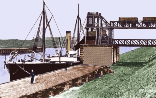
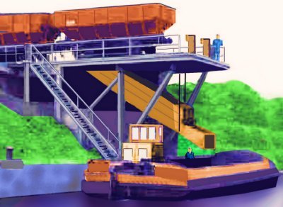
A variation on the coal hoist idea was used at Partington on the Manchester Ship Canal where two railway tracks ran from a raised area of ground to a tower on the bank. The loaded wagons were rolled out along the upper track by gravity, at the tower they were lowered to the chute and tipped, then rolling back out on the lower level and back to shore by gravity. The Partington coaling stage was for supplying coal for ships fuel, not to load ships with a coal cargo, however the basic principal is similar to the larger hoists used for loading colliers. The design of the standard N gauge coupler would theoretically allow an intrepid modeller to duplicate this procedure but emptying the wagons would not be a practical proposition. The sketch below is based on a tracing from a photograph taken in about 1900, there were a series of these hoists along the bank, and other quays on the opposite bank, the sketch is simplified to show the design of the hoist.
Fig ___ Coal hoist at Partington
There was at least one of the coal towers apparently well maintained at Partington into the 1970s, I am not sure what it was used for, possibly loading barges with domestic coal.
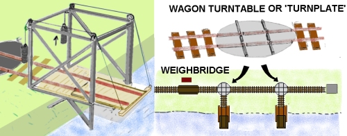
At smaller ports and river or canal coal berths where coal was loaded into barges the wagon did not need to be lifted to clear the side of the hold and a simple tipping platform was commonly used, usually fed from a wagon turn-table. These platforms came in various designs, there is a preserved example to be seen at Wigan Pier Museum which consists of a platform set into the quay wall with curved bars to hold the wagon wheels, the 'works' being hidden underneath the quay surface.
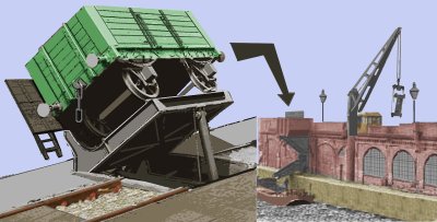
Where river berths were used, requiring a short jetty extending out from the bank a simple hinged platform rather resembling a drawbridge was sometimes used. Most of the examples of this type had an external frame to support the wires, pulleys and counter weight. The wagon would be rolled out onto the platform and the end door opened, once the man was clear the platform would be released and the weight of the loaded wagon would tip the thing over the ship or barge. Once empty a counter-weight enabled the staff to pull the platform back to the horizontal so the wagon could be rolled off again. These draw-bridge tippers were common in the small harbours on the banks of the Severn Estuary handling coal from the collieries of the Forest of Dean and there are several good illustrations on the books on the Severn & Wye Railway mentioned in the bibliography.
Fig ___ Coal tipper as used on the Severn Estuary
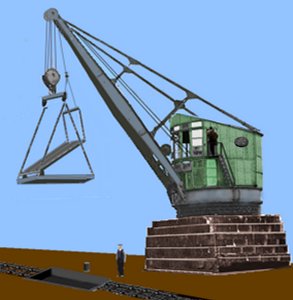
There were other variations, in one the wagon was tipped sideways against a wooden frame by a hydraulic ram, emptied through its side door (there was a gap in the frame to allow the door to open), the coal falling into a chute which fed down into the barge below. If the drop was substantial there would be a steel spiral track inside the chute so the coal would not break up due to the long fall. At some ports a heavy crane was used to lift a frame which could then be lowered into the ship or barge and tipped, again this was done to reduce the breakage. The frame is shown near vertical however when working the platform would never exceed an angle of about thirty degrees to avoid damaging the wheel bearings on the wagon. There were a row of these cranes at a wharf in Liverpool. Both these are shown in the illustration below.
Fig ___ Side tipper and coal crane
The tipping platform was quite a common feature at docks, usually associated with a rather large crane. The example below is,or was, a large electric crane in Hull docks, on this example the main platform remains level and a sup-platform tips the wagon. This is less complicated than arranging the main platform to alter its angle and allows the platform to e exchanged for a grab for bulk minerals coming the other way.
Fig ___ Crane with tipping platform at Hull docks
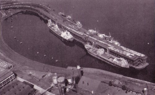
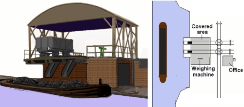
A 'coal staith' is a raised section of track which permits the coal to be tipped into the ship or barge via a chute. The wagon hoists of South Wales are technically staithes but the term is most often associated with the North East where ships and barges were often loaded from hopper waggons. These were sometimes run on a raised section of track on the bank but at the ports the staith would be a heavy timber structure to which ships tied up. In the photo below, dating from the mid 1950s, the staith is the pier like structure in the upper part of the photo, there are two in fact the outer run has two tracks, the inner has three.
Fig ___ 'Coal staith' at a port in Northumberland
The example shown below is a staith on a river in the North East, sketched from a photo dated 1971, the chute can be raised and lowered to allow the barges to get underneath easily and to reduce the drop at the end to avoid breaking the coal.
Fig ___ River or canal side 'coal staith'
The approach track had a loop on it and lead up a slight gradient to the staith. The loco would push the rake until the end wagon reached the discharge point where it was emptied and its brakes applied, the loco would back off and the points at the top of the loop would be thrown, the wagon would then have its brakes released and roll back into the loop.
A variation on this approach was used at one coal loading point on the Grand Union Canal, here the wagons used tended to be conventional types and the bottom doors, assisted by man-with-shovel method was used. The railway lines were lower, which might make it an easier proposition to model, for a canal parallel to the track turnplates can be used as shown in the sketch.
Fig ___ Canal side 'coal drop'
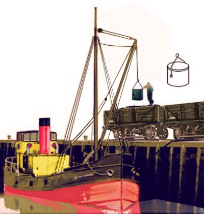
Coal unloading is a much more promising side to the business from the point of railway modelling. The facilities, even if dedicated, can reasonably be small and compact. Colliers were unloaded by shore cranes using rattan 'coaling baskets' or steel tubs, both of which were filled by men working with shovels. The tubs were cylindrical and generally about 4 foot wide by 4 foot deep. They were suspended from a steel stirrup which was pivoted just above the centre line, so the tub could be easily tipped into the wagon. The coaling basket is not easy to describe, and would be tricky to model, for those with the nerve to try they are now sold at 'Habitat' type shops as 'log baskets'.
Fig ___ Unloading a 'Clyde Puffer' using a coal bucket
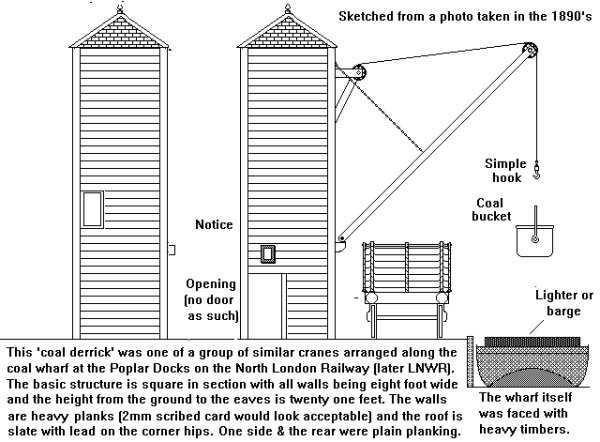
Even at dedicated ports, or dedicated berths in a port area or on a river, the facilities could be simple in the extreme. The sketch below shows a basic 'derrick type crane mounted on a river bank. There was a single track running in front of the crane with two more run behind. There were several such cranes on the berth, separated by perhaps ten wagon lengths. In this way a rake of wagons could be positioned and the first wagons loaded, the rake would then be shunted along and the next wagons in the rake could be loaded. For modelling purposes a pair of these cranes, mounted about six wagon lengths apart, would represent an acceptable compromise. The sketch was made from a photograph taken in the 1890's but the cranes probably lasted into the 1930's and possibly into the 1950's. Between two of the cranes was a proper crane, capable of slewing (swinging round on its axis), similar to the illustration shown in Fig ___ XXX above. This would justify the odd load of something unusual at the berth (the crane was a light affair so do not make the load too large).
Fig ___ Coal derrick as used at Poplar docks
The rail mounted steam cranes shown below were both railway company owned and both were used for unloading coastal craft or barges, the smaller example (actually a medium sized crane) employed a coaling bucket as shown above, the larger crane (sketched from a photo taken in about 1910) has a large grab. Both examples were photographed before World War One, by the 1920s such cranes often had a simple wooden or corrugated iron 'body' over the boiler and gearing. The figure shows the scale of both cranes (see also Wagon Loads and Materials Handling - Materials Handling - Lifts, hoists and cranes).
Fig ___ Medium and large railway owned steam cranes
Cranes equipped with grabs for unloading coal from smaller vessels were not a common feature of docks other than at specialised installations such as power stations, the coaling tub was much more common right into the 1940s. Berths handling purpose built colliers often had grabs by the time of the First World War but the cost of manpower remained comparable with the cost of maintaining the grabs until the outbreak of World War Two. Since the war specialised and rather larger bulk mineral carriers have replaced the smaller general cargo ships on this traffic and quays devoted purely to coal traffic have become the norm. These have specialised gantry cranes using grabs which feed onto conveyor belts and thence to stockpiles. The conveyor belt for moving coal and other bulk materials was in use from the later nineteenth century.
Docks - Bulk liquids (oils and latex)
The first purpose built ocean going steam/sail bulk petroleum oil tanker was built in 1886, 300 foot long and carrying 2,307 tons of oil in a single tank. By 1918 steam ships carrying 8,000 tons were in operation. By 1930 the 12,000 ton tanker, with triple expansion steam engines at the back and a small section of accommodation over the centre of the ship (to give the deck officers a better view forward) was standard.
The oil was pumped ashore in thick (typically 8 inch) reinforced rubber hoses, usually into large tanks. A small ship might however be loaded from rail tankers in a small dock, and fuel was sometimes delivered either direct to the ship at the quay or into 'bunker barges' for transferring to ships. One point to note is that the rubber hose would be supported clear of the quay wall and/or ships rail, using a simple crane on the quay or a derrick rigged on the ship or barge. On larger purpose built berths the hoses were supported from a gantry to ease the job of hauling them on board the ship.
Fig ___ Oil hoses being used to bunker (refuel) a ship in the 1930s
Bulk (petroleum) oil cargoes might consist of oils of two basic types: Light oils - Including gasoline, white spirit, alcohol, kerosene or light gas oil (diesel) and Heavy oil - Crude oils, creosote, asphalt, lubricating oil. Fuel oil falls somewhere between these two, it is mainly composed of unrefined residues from the refining process and it is used in specially designed engines and for fuelling boilers. This stuff usually has to be heated so it will flow.
Non petroleum based oils shipped in bulk include vegetable oils (palm oil, kapok oil, linseed oil etc), whale oil, molasses, pilchard and herring oil and animal oils (such as neatsfoot oil, tallow oil and lard). These were usually shipped in barrels but by the later 1930s deep-sea general cargo ships would often carry consignments of these less dangerous bulk oils in built-in convertible tanks as part of their cargo. When not used for oil the tanks could be used for ballast (sea water) or fuel oil for the ship (the tanks required cleaning and a degree of preparation for loading the oil, and after discharge had to be cleaned again for their alternative purpose). Hence it is perfectly acceptable to have railway tankers delivering or receiving a bulk 'oil' cargo from a conventional cargo ship. The standard hose for loading and discharging these tanks was four inch diameter, the ships pumps would normally be used to pump the cargo ashore.
Vegetable and animal oils are classed as oils if they are liquid at normal temperatures or fats if they are liable to solidify at those temperatures, however the distinction is very blurred. Where the oil was likely to solidify, or become too thick for efficient pumping, steam heating was fitted to the tank - This was often removable to allow the carriage of other cargo. In the days before containers general cargo ships could be in port for weeks and had a substantial crew, so fitting and removing pipes, cleaning and coating tanks etc were practicable if tedious options.
All oils are more or less inflammable however vegetable oils are generally safe enough providing they do not come into contact with rags, textiles or fibres such as Jute, in which case they can spontaneously combust (a particular problem with linseed oil). In the book on rail tankers mentioned in the bibliography is a rectangular tank wagon liveried for the splendidly named 'Scottish Fish Oil & Guano Co.' which would make an interesting addition to ones wagon fleet. Fish oil is produced mainly from pilchards, the entire body of the fish is steam cooked and then pressed to extract the oil, the resulting solid waste is sold as 'fish meal' mainly as an animal food. Fish oil is an important material, chemically modified it is used in soaps, detergents, protective coatings, alkyd resins and since the late 1930's it has been used as the base for margarine and shortenings.
Bulk liquid latex could also be carried in a general cargo ship's tanks, although because this requires ammonia to prevent the rubber coagulating there were additional restrictions, the double bottom ballast tanks (running along under the holds at the very bottom of the ship) were unsuitable as the ammonia tended to leak out (in which case the rubber began to set and the actual hull plating had to be removed to get the stuff out). The 'after peak' tank at the stern of the ship also tended to leak as the ship moved, and proximity to the brass liner for the prop shaft also made this inadvisable. 'Deep tanks', lower down on the ships sides but accessible from the deck, and the 'fore peak' tank in the bows of the ship were however considered suitable for latex. When carrying latex the tanks would be coated with paraffin wax (they also required pressure relief valves to cope with ammonia being given off). I believe this material was pumped directly into rail or road tankers for transport to the works (almost all of which were located close by the docks). See also 'Lineside Industries - Industries associated with docks and harbours'.
Sea-going ships & barges
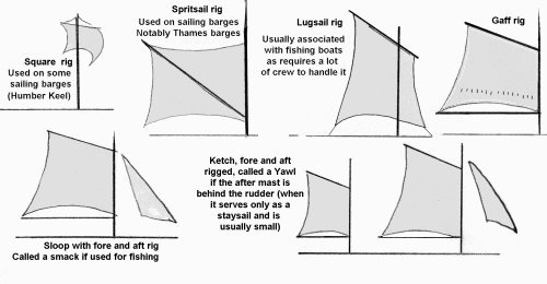
Sail remained the main form of propulsion for smaller craft into the early 20th century, there are a lot of complicated terms used regarding sails, the sketch below shows some of the more common layouts used on smaller craft. The spritsail allows a very large sail with the mast set well foreward, hence its use on the Thames sailing barges. The Lugsail is a variation on the square rig but runs fore and aft, this rig is fast and sails close to the wind. It is mainly associated with fishing boats as it has to be lowered to the deck and lifted round the mast when 'tacking' (changing course with respect to the wind), which requires a lot of crew. The gaff rig was probably the most common on small coastal vessels. The advantage of the gaff rig was that the gaff (the upper boom supporting the sail) could be lowered a bit, allowing the bottom part of the sail to be secure to the boom with the ties visible on the sketch, this was called reefing down (the square rig could also be reefed down but that could not be done from the deck). The sloop (smack if it is a fishing boat) shown bottom left is gaff rigged but with a foresail, these tended to be built for speed. A ketch tends to be slightly larger, as shown bottom right, quite capable of sailing across the North Sea to European ports, these ranged a long way from home.
Fig ___ Sails used on smaller craft
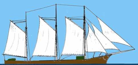
If you have more room you could opt for a Lugger, two masts both with lug sails, or a Brigantine, which has a two masts, the after one being gaff rigged with (usually two or three) square sails on the foremast. Three masted types would be the Barquentine which has a gaff sail on the after mast and two masts with square rigged sails, or the schooner which has gaff rigged sails on all three masts (sometimes with square sails at the top of the front and middle mast, hence called 'topsail schooners', these were removed when engines were fitted in the 1930s). The definition of a schooner is actually two or more masts all fore and aft rigged, but the term is normally associated with three masted ships.
Sailing barges were a mainstay of inland transport right into the mid nineteenth century. They could reach a long way inland following the rivers and 'broad canals', they are generally simple in form and hence not difficult to model. There were regional variations of course for example the Norfolk Wherry was exceptionally wide for its length. One problem is that most illustrations depict the vessels belting along with all sails set whereas we are much more likely to want the sails furled or removed completely during loading and unloading.
The sails could be hauled in, rolled round the boom at the base of the sail or removed completely depending upon the circumstances. Sailing barges, with their small crew, were likely to simply furl the sail to save time and effort when getting under way.
Fig ___ Norfolk Wherry with Sails Furled.
Small coastal sailing ships often had a larger carrying capacity and would therefore be more likely to remain in port longer. They usually had a bigger crew and it was not uncommon for the sails to be removed completely when working cargo.
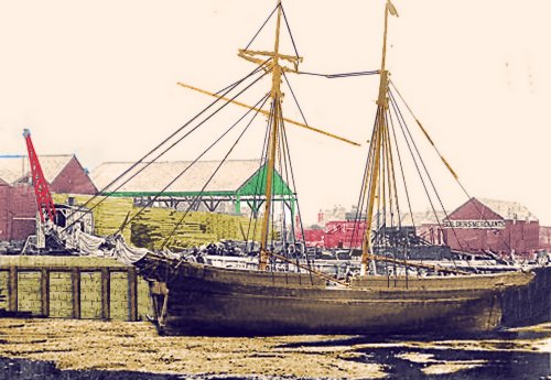
This makes for an easier modelling project as it is quite difficult to simulate the folds of canvass in our scale. The sketch below shows a Tamar Barge coasting vessel with furled sails, sketched from a photograph showing her unloading coal at a jetty in the early 1930's. If the sails were removed the top and bottom poles on the after sail would be resting on the roof of the after cabin whilst the poles on the foremast would be hoisted pretty much as shown to keep them out of the way. The upper pole on the foremast was sometimes rigged with a block and tackle to lift cargo between the ship and the quay.
Fig ___ Tamar Barge with Furled Sails
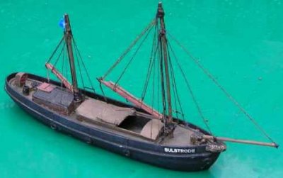
Note the vessel has sails which lie fore and aft, this arrangement requires less man-handling than the older 'square rig' type sail.
The ketch Garlandstone, now preserved at Morwelliam Quay has this kind of sail but this was a nineteenth century innovation introduced by 'yachting types' who found the ketch a useful little vessel for their purposes. The rig was adopted by commercial ketches in the mid nineteenth century but prior to this date the ketch usually had square sails. A ketch is a two masted ship, typically able to carry a hundred tons or so and usually used for coastal or near-continental trades.
Ketches represent a useful size vessel for a model railway, visibly larger than a 'boat' but small enough to fit in any harbour or river berth. Prior to the introduction of iron hulled ships the average ratio of length to width (or 'beam') was three to one, resulting in generally 'tub' shaped hulls. The only problem with this is that commercially available model ships, even the sailing variety, tend to be longer and thinner in plan.
Ships of this type are not easy to scratch build, but you might be able to find a commercial model to provide the hull and some of the fittings. I found a small kiddie's wooden model on a market stall imported from Taiwan which had a beautifully carved hull to form the basis of a small sailing ship. You can use old paint brush handles for the masts with sanded-down cocktail sticks. Ships of this size had the difficult to model rope ladder arrangement for access to the upper parts of the mast, to model these is tedious but necessary if the kit provided nothing suitable.
Ocean going sailing ships were rare by the 1940's although a few remained in revenue earning service trading all round the UK coast and near continent into the early 1960's. The West Country 'Topsail Schooner' Kathleen & May is now part of the national Ship collection, she has been fully restored and can be seen at St Katherine's Dock in London.
Fig ___ Kathleen & May (West Country Schooner)
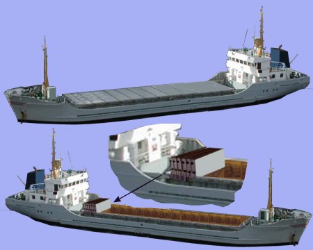
Up to the 1970's even sea-going cargo ships were relatively small by modern standards. They were usually of a general purpose design intended to carry mixed cargo but capable of loading goods in bulk if required. This type of ship is usually called a 'break bulk' ship and they were always equipped with their own cranes or derricks to handle the cargo.
By the end of the 1980's they had largely been replaced by container ships and specialised vessels such as palletised fruit carriers, car-carriers, oil and gas tankers, bulk ore and mineral carriers and the roll-on/roll-off (Ro-Ro) vehicle carriers. Smaller coastal vessels still operate today however, and not everything goes in containers, coils of steel sheet and wire are shipped 'loose' and bulk materials such as coal and ore are moved by sea.
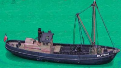
A small steam or motor coaster of about 200 tons works out at about 12 to 18 inches in N, which is quite a reasonable size to play with. All-aft accommodation and engines was virtually the standard layout for small coastal steamers from the 1890's. Often the navigating bridge on these vessels was open, the helmsman and officer of the watch, if the vessel was large enough to boast one, having to make do with a thick coat for protection from the elements.
Fig ___ Small coastal steam vessel.
Hatches and Hatch Coamings
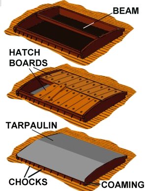
Cargo carrying vessels need to cover the hatch (the hole in the deck where the cargo is loaded), on a small boat such as a narrow canal barge a beam mounted above the hatch can be used to support a tarpaulin sheet, roped down to the sides. On larger boats, and anything likely to go to sea, something more substantial is required. The standard method used on ships of all sizes was from many years the hatch beam supporting hatch boards. This consists of a raised wall around the hatch called a coaming, at either end of which (one at the front one at the back) is a mounting that takes a heavy beam (originally wood, later of steel). Hatch boards are then laid between the edge of the coaming and the beam, forming a gently pitched 'roof' over the hatch. This is then covered with a tarpaulin which is secured around the sides using a metal bar held in place by wooden chocks driven into a metal frame, on smaller craft a rope was sometimes added across the tarpaulin as well.
Fig ___ Typical hatch, beam and boards
Where the hold was long the beam would become unwieldy so a series of transverse (side to side) frames were used, each with a support for the beam at the apex. In this way a part of the hold could be exposed whilst leaving the remainder covered. Larger barges and lighters (barges used to unload ships at anchor) also used this system of hatch covering, the coaming would in all cases be no less than a foot high, on a small coaster it might be two feet high and on a 2000 ton coaster as high as three feet from the deck.
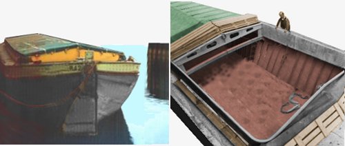
The example below left shows the end view of a large barge, note the clips for the end of the canvas cover. The examples below right is a lighter being prepared to take on a cargo, the canvas has been folded back, the hatch boards lifted out and the short beam removed (it is lying on the deck beside the hold).
Fig ___ Typical barge hatch, showing cross-support for beam and boards
For larger ships the size of the hatch boards would become a problem so a large transverse support might support additional beams, allowing shorter hatch boards to be used, however in the space available to the average railway modeller such ships would be impractical.
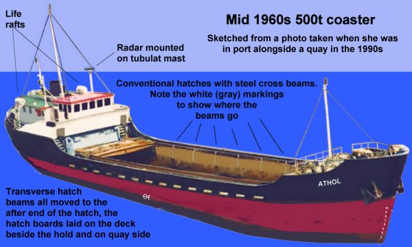
Fig ___ Typical 1960s coaster with conventional hatches
The colour of the tarpaulin sheets used to cover the hatches has proved an elusive topic, as far as I can tell prior to about 1930 they would have been a dark grey, cotton canvass waterproofed with tar. From about 1930 to about 1960 most would have been a light grey colour, with those used on smaller coasters sometimes being a reddish brown colour. From 1960 green seems to have become more common but light grey continued in use into the 1980s. If anyone has any more accurate information on canvas used for hatch covers I would be grateful if they could pass the details by e-mail.
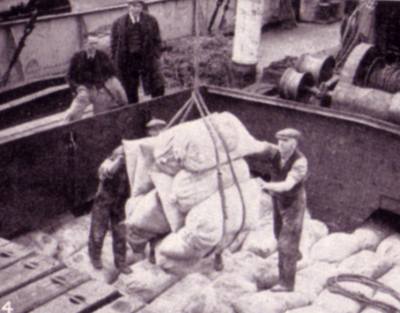
The illustration below shows a hatch being worked in the later 1930s, the ends of the hatch boards removed from the open area can be seen in the lower left, stacked on top of the boards for the adjoining section. It was common to only partly open the hatches when working cargo, for one thing this made it easier to deal with rain. Note that the top end of the sack was still tied off rather than sewn at this time.
Fig ___ Working a hatch in the 1930s
In the 1940s a new type of hatch started to appear, called the sliding hatch cover, this consisted of a series of slabs running from side to side across the hatch which were pulled backwards to fold up concertina style at one or both ends of the hatch. This kind of hatch has several advantages, it is quick in operation and requires a smaller crew to handle it, but it cost more and so did not catch on for some time. These were never very common on coasters prior to the 1970s, when they started to gain favour. The plus side here is that they are easier to model than conventional hatches. One common type is the McGreggor single pull design sketched below.
Fig ___ Typical sliding hatches
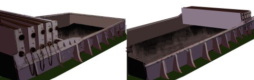
Fig ___ Appearance of sliding hatches in use on a coaster
Ship, Barge & Boat Models for docks
Note - The markings used on ships and some useful detail on flags and ensigns can be found in Appendix One under 'Canals, rivers and coastal shipping'
The two Langley narrow boats (motor A18a and butty A18b) and the Fleetline narrowboat 'coal barge' (BN-1) would serve for layouts set between the First World War and the early 1970's. These narrow barges were not confined to the narrow canals of the Midlands but wandered throughout the canal network and even into some ports, however they were not sea-going and so are more suggestive of the inland waterways.
Probably the simplest option suggesting a larger port is to provide some 'lighters', barges which were loaded by ships at anchor and carried the goods to the quay (or vise versa). Lighters were quite large, often larger than the smaller coastal craft, but they had no engines and no accommodation. They were moved about by tugs and up to the 1960's most tugs were rather small vessels which do not take up too much room. Most river ports would have a few of these on hand, larger ports such as Liverpool and London would have a great many.
Lighters were large, usually larger than most barges, some had vertical bows and stern with the rudder sticking out at the back (like a large barge) but a lot had a distinct cut-away at the bow and stern. Although large these could be moved about by a man (or two) working a long oar called a 'sweep'. This was even seen on rivers where one would assume the current would be too strong.
Port or harbour lighters
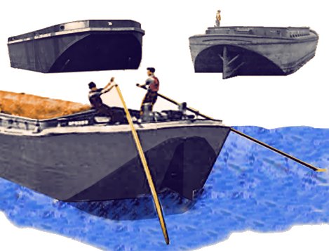
Barges were also used in the same way, and they are easier to model (at least I find them so). Noch offer a model suitable for OO layouts in their range. For N Gauge layouts the Airfix military 'Pontoon Bridge' set includes five barges which can serve for a 'barge' type lighter, although they are rather deep for use 'as-is' and benefit greatly from being reduced in height by cutting them in half. The centre of the lighter has a low raised coaming on which ship-type curved supports were mounted to carry 'hatch boards', these then being sheeted over with canvass secured by wedges in the coaming. At each end there is usually a rectangular hatch about three feet square, for which a square of 30 thou card will serve in N. The photo shows an Airfix barge being modified in the way described.
Modelling lighters
There are European barges available from some continental firms which might serve on a more modern layout but these are rather big for a British setting although they might serve in a deep-sea docks. Noch offer a dumb barge (35720) in their OO range, this is acceptable for a British harbour lighter in OO but this scales out very large indeed in British N. For a British harbour lighter (see also Appendix One - Canals, rivers and coastal shipping) it is probably better to go for a scratch-build using 1" x 2" planed timber (scaling out at about 12" x 24", cut this in half to reduce the height to about half an inch or a quarter inch when loaded) and sand to shape. For a loaded harbour barge or lighter life is easy, just add the top of the hatch, for an open barge you can get away with modelling the hatch coaming and adding a 'piled load'.
The Noch 1:160 Continental N scale range also offers a pilot boat (35750) and tug boat (35710) both on the same hull, a modern European powered barge (35730) and a modern powered barge tanker (35740). The powered barge is again rather large for N, and requires rather a lot of modifications, the tanker barge, although requiring modification, can at a pinch be pressed into service for N Gauge, but the Eastern Models (formerly Novo and before that Frog) 'Shell Welder is an altogether better option.
Tugs
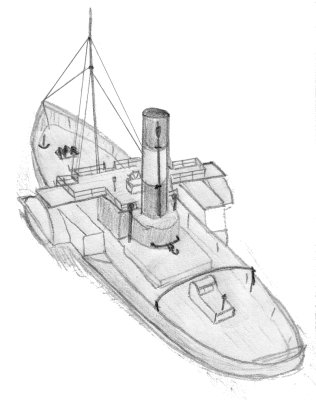
There were many designs of tug, by the mid 19th century the paddle tug was commonplace, by the beginning of the 20th century the screw propeller dominated and these are much easier to model (unless you can find the old Airfix 1:600 scale kit of the Great Eastern, a good starting point for a paddle tug although better for a paddle ferry). The last steam engined paddle tugs to be used in Britain were used to berth colliers at the staiths at Seaham harbour. One of these paddle tugs, the Reliant, is preserved in the National Collection. The tow hook on a tug is always somewhere close to the centre of the hull and mounted on a swinging arm so the pull on the hook is always straight to allow the quick-release to operate. The steering position moved from the rear of the tug to in front of the funnel toward the end of the nineteenth century.
The sketch below was made in the mid 1970s, when I built my first layout, and shows the salient features of a paddle tug (intended for a pre-grouping era layout). Note that the steering position is in the open and the chap steering stands in front of the wheel. Note the tow hook just behind the mast and the bar running across the after deck to prevent the tow rope from catching. Access to the bridge (steering position) is via a stair at the front.
Sketch showing main details for a paddle tug
The photo below shows a model paddle tug, points to note are the two lights, one above the other on the foremast and the arched metal bars running across the after deck so that if the tow line went slack it would not catch on any deck fittings.
Typical paddle tug
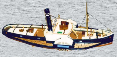
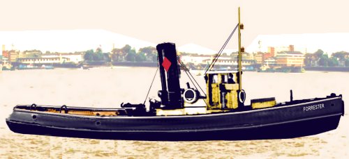
Steam tugs, paddle or screw, offered many advantages over using horses and rowing boats to maneuver ships in port. There is a preserved example, the Mayflower built in 1861, at the Bristol Industrial Museum & Maritime Heritage Centre, the example shown below is a typical British screw driven type and might have operated in any British port.
Typical British steam tug
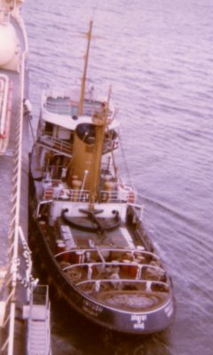
The Noch tugs are 18cm long, corresponding to almost ninety feet (26m) in British N scale, which is very big. The fully enclosed wheelhouse as on the Noch model dates from about the late 1920's. There is a preserved steam tug called the Mayflower at Bristol Docks museum, she is 65 feet (19.8m) long by 12 feet (3.6m) beam at her widest point. The Noch models have the tall cylindrical smoke stack of a steam vessel and would serve for a larger dock scene up to the 1950's at a pinch. Replacing the funnel with a more modern shape would allow them to be used for periods between 1940 and the present day.
The example shown below was photographed in Bombay (since renamed Mumbai) harbour in about 1980, note the way the hook is attached and the bars across the after deck. Tugs of this type operated from the late 1930s to about 2000.
Typical motor tug
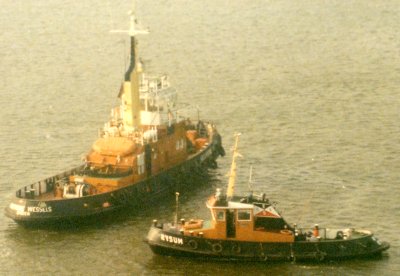
Tugs come in a range of sizes, the two examples shown below (again in India in about 1980) show typical small and medium sized vessels. Both are post war types, suitable for layouts set from the later 1950s (when they would have been new).
Small and medium sized motor tugs
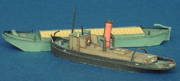
I have recently heard of a range of card models from a company called 'Paper Shipwright' (website at http://www.papershipwright.co.uk ) which includes a British steam tug from 1915, also supplied is a rather good kit of a typical barge. The tug has an open wheelhouse, suitable for layouts from about 1910 to 1940. The photo below is courtesy and copyright David Hathaway, the proprietor of Paper Shipwright models.
Paper Shipwright Tug and Barge
Ship Models and modelling ships
Modelling ships is not actually difficult, although the complex shape of the hull is difficult to get right. One option is to take a piece of planed softwood and plane and sand this to shape, tricky to get it symmetrical but if you make a set of curved templates in post card and use these to mark the sides you can get quite a reasonable finish. For flat sided boats and barges this approach has a lot to commend it.
An alternative is to use the hull from a commercial model ship, although these usually require cutting down to the waterline. I did try using expanded polystyrene ceiling tiles with a hole cut in which the ship sat, the texture on the top served well as 'water' but I found that when I left the model in place the polystyrene attacked the plastic and softened it. To produce a waterline model I now sit the hull on the supplied base on a flat surface then use a piece of scrap wood about the right height with a broken hacksaw blade resting on it to scratch round the hull. This line can then be cut with a razor saw.
War ships are the wrong shape, usually much too long and thin for our purposes, however there are a few models available that can be cut down in this way. One example is the Revel 'Light ship', the prototype was anchored over a patch of shallow water, serving as a floating lighthouse. The hull shape is fine although the decks and superstructure need replacing but many of the supplied parts can be pressed into service.
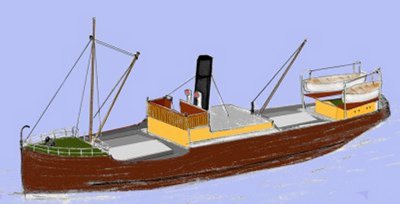
The sketch below (made many years ago and unfortunately long since separated from the associated notes) is based on a photograph of a small coastal steamer at about the time of the First World War (note the open bridge), the Light Ship hull could serve well for such a model. This vessel is slightly unusual in that it has a crane instead of a derrick over the after hold and two lifeboats (on raised davits with wooden platforms beneath them), rather than the single boat more usual on a ship of this size.
Fig ___ Sketch of a small steam coaster
The Revel modern trawler Kandahar has lovely lines to the hull, as a trawler it serves from the 1930s to the end of the railways involvement in fish traffic in the later 1960s. It can be used as the basis for a number of ship types but the work involved generally requires a complete replacement of the main deck. There was an article by Derek Church in the July 1984 Scale Trains magazine on converting this kit to represent an OO scale steam drifter (a type of fishing boat, see also Appendix One - General Information - Fishing boats and ports) and an OO scale small steam coaster. This article would be worth perusing if you model in OO.
I have recently heard of a range of card models from a company called 'Paper Shipwright' (website at http://www.papershipwright.co.uk )which includes a small coastal tanker to 1:160 scale, kit number PS27 the SS Ben Read, a coastal steam tanker dating from 1923. The photo below is courtesy and copyright David Hathaway, the proprietor of Paper Shipwright models.
Paper Shipwright Ben Read coastal tanker model
This range also includes a combined kit of a small British outline tug with a suitable barge as mentioned above.
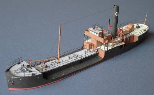
The well known Eastern Models (formerly Novo and before that Frog) kit of the coastal tanker Shell Welder scales out close enough to British N to be usable (it is actually about 1:200 but looks acceptable on a layout). This needs to be cut down to the waterline as this kind of vessel would not normally be 'beached' other than by accident, but otherwise it can be used unaltered for any post war layout (you can get away with it as a later 1930s vessel, but only just). My own model is currently in storage, the photo below was taken at a stand run by the Manchester Model Boat Club at a steam rally in about 2002, it shows a larger scale model of the same ship, with the old Frog model beside it. The level of detail is similar on both. Unfortunately I cannot credit the builder as their name was not displayed on the stand.
Fig ___ Model of the Shell Welder coastal tanker
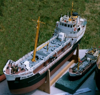
This is a very nice kit, originally tooled by the British firm Frog, although the design of the ship is suitable for post war layouts it can be 'back dated' with a little care. Unfortunately this kit is difficult to find these days.
The prototype Shell Welder was subsequently converted into a bulk carrier, transporting coal, broken stone and the like, and the model is not difficult to modify to represent such a vessel. The deck is retained but the foremast is relocated forward and a raised 'coaming' is added carrying a set of 'folding hatch covers'. If the hatch covers are closed no additional work is required, if they are part or fully open you have to cut away the deck inside and add a little detail to the insides and tops of the coamings. See Appendix One - Canals, rivers and coastal shipping for information on the design of hatches used on coastal craft. No cranes or derricks are required as these ships rely on shore equipment. The two variations on the Novo kit would occupy a quay some 2 feet 6 inches long and justify block trains of both coal (or other minerals) and oil.
Fig ___ Converting the Shell Welder coastal tanker to a bulk carrier
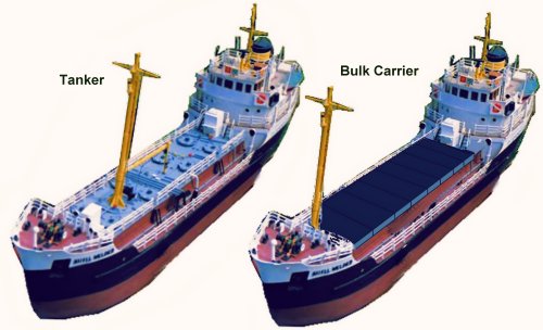
The example shown below is typical of the breed, the ship has sliding hatch covers and is roughly the same size as the Shell Welder.
Fig ___ Typical coastal bulk carrier
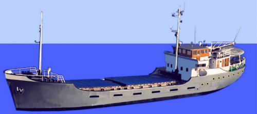
If your port is too small to provide the required equipment to unload a bulk carrier (which could be as simple as a crawler crane with a grab) you can make a 'self discharging bulk carrier' by adding a couple of electric cranes, either one at each end of the hold (offset one to either side of the ship) or two side by side in the centre (each with their jib laid diagonally across the hatches, one forward and one aft, when under way).
For more general cargo you can again modify the Shell Welder kit, the photo below was taken in Istanbul in the early 1980s but vessels of this type would have been seen in British ports from the 1940s on. She has two hatches, each with a derrick, and the older style of hatch boards with canvas covers, making her visually rather different to the tanker model.
Fig ___ Two hatch coaster
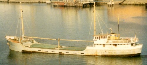
Some of the general cargo coasters had multiple derricks, the example shown below has two for each hatch and looks substantially different from the tanker model. Having two derricks per hold allowed the ship to use 'union purchase', one jib is fixed in position over the hold, the other over the quay and the load suspended from both. This arrangement is quicker than a crane as the jibs do not have to move and the load is lifted and lowered with very little swing (see also 'Wagon Loads & Materials Handling - Materials Handling - Hoists and Cranes'). The example shown has the more modern sliding hatch covers discussed above. The photograph was taken when the ship was changing from one berth to another, it would not put to sea with open hatches and derricks not secured.
Fig ___ Two hatch coaster with sliding hatch covers
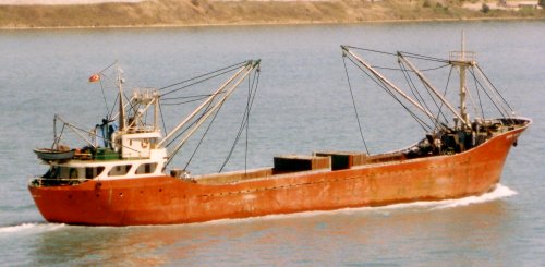
If you fancy trying to 'kit bash' or scratch build small ships C. V. Waine's 'Coastal Steamers and Short Sea Traders' is a book worth finding at the library. The all welded ship only appeared in the 1930's, and the Board of Trade required that riveting be used on high stress areas of the ship right up into the 1970's (you will often find a line of double rivets along the top edge of a ships hull, there is a model in the Science Museum, London, of a P&O LPG tanker, the Gazana, which has this detail). There are some preserved vessels you can see to obtain detail, the Robin, a small coastal steamer, is (or was) on display at St Katherine dock, next to the Tower of London.
The main British coastal tanker company has been Rowbottoms, but I cannot find my notes on their livery (they were taken over by P & O in the later 1980s).
The main British company dealing with dry cargo coastal traffic (certainly since the 1960s) has been F T Everard & Sons Ltd, based in London. Their ships have a 'light stone' hull, the funnel is a slightly richer version of the same colour, the accommodation block is white or stone, the decks are usually a mid green or dark grey. In the sketch below note that the lower part of the signal mast (on which the various lights are mounted and up which signal flags are hoisted) is discoloured with the funnel exhaust.
Fig ___ F T Everard company colours
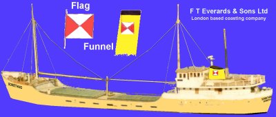
Train Ferries
Train ferries are ships equipped with rails to carry railway wagons, locomotives are not carried unless they are being exported. The usual arrangement is for the ship to tie up alongside a jetty with its stern against a floating ramp called a 'link span'. The railway lines from ashore run out onto this ramp and so onto the ship.
An American modeller has used a railway wagon transporter vessel as a fiddle yard on his freight only-line, the 'ship' is actually a small moveable table which can be turned end-for-end. The stock is taken on board and the ship 'departs', subsequently 'arriving' with what is presumed to be a fresh set of wagons for the system. Such transporter ships and barges are quite common in the USA, often simply used for crossing wide rivers where a bridge would be a difficult and expensive alternative.
In Britain train ferries have been confined to ships used for Continental traffic for many years, although the Forth Bridge was built to replace such a system, the loading ramp for which is still in place on the Burntisland side of the river.
Cross channel train ferries first appeared in 1917 (during World War One) to supply the front lines. Three ships were built for this traffic each with four tracks on deck accessed via the stern. They operated between Southampton and Dieppe and also between Richborough (in Kent) and Calais, where a special military railway line was laid to the port. Later a service between Richborough and Dunkirk was established. The link spans (which carry the railway tracks from the shore to the ship) were identical at all five ports.
With the end of the war all three ships were laid up until 1923 when they were purchased by a joint British-Belgian operation. In 1924 they entered service running between Harwich and Zeebrugge using the old military link spans recovered from Richborough and Southampton. In the depression of 1929-1932 the British end of the organisation went bankrupt and the LNER took over. These three ships were requisitioned during the second world war and only one survived, renamed the Essex Ferry she re-entered service between Harwich and Zeebrugge in 1946 and was only broken up in 1957. The sketch below is based on a poster produced by the LNER and the detail appears surprisingly accurate when compared to photographs of the prototype.
Fig ___ Original ex WD train ferry
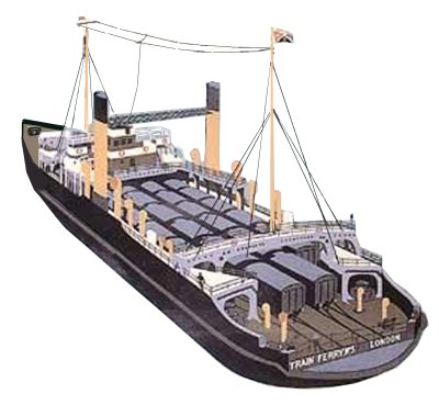
In 1936 a second service was set up by the Southern Railway between Dover and Dunkerque using three ships each of which had two tracks laid onto the stern with four tracks on deck. They could carry twelve international sleeping carriages or twenty four forty foot wagons and an enclosed upper deck had a garage for 25 motor cars. The illustration below is based on a poster produced by the SR advertising this service. Note the funnels are mounted fore and aft rather than at the sides as on the old WD ferries.
Fig ___ 1930s Southern Railway train ferry
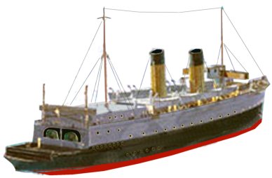
New ships were built in 1951 and in XXXX a former Roll-On Roll-Off ferry, converted for rail traffic, was chartered and renamed Sealink Vanguard. The Sealink Vanguard was fitted with a lift to allow additional tracks on a lower deck.
After 1967 additional sailings from Harwich also ran down to Dunkerque but in 1982 this service was abandoned, mainly due to the lack of suitable ships, investment for which had been prevented by the abortive channel tunnel project of the 1960's and 70's. The service between Harwich and Zeebrugge was also reduced at this time. The Germans were annoyed by this and re-routed their traffic to Cuxhaven in Holland, where it was transferred to road vehicles and brought across on roll on-roll off vehicle ferries. The small port of Felixstowe handles a lot of roll-on-roll-off lorry traffic as well as LPG and chemical tanker ships, although small in size it is today one of the largest British ports in terms of volume of traffic.
The Harwich Zeebrugge service ended in January 1987, the remaining trade being concentrated at Dover to maintain international links ready for the channel tunnel. The Dover-Dunkerque link was finally shut down in 1995.
Typical train ferries would be about thirty inches long by seven inches wide in 1:148. The ferries built by BR in 1951 were about four hundred feet long by nearly a hundred feet wide, they had four tracks on deck with two points at the after end so only two tracks passed over the stern onto the quay. They typically carried about thirty wagons on each trip.
Train ferry ships do not have the high sided accommodation of most sea going ferries, railway rolling stock cannot climb stairs and experiments with lifts and the like have generally proved unsuccessful. They usually have an open central deck with two funnels arranged one on each side of the ship, older vessels had these half way along the ship but the Sealink Vanguard was a more modern slab-sided ship and had them at the stern.
There will be two masts on such as ship, one above the main navigating bridge toward the front of the ship and one near the stern. The former is the 'signal mast' and would have a cross-tree to support the signal flag halyards near the top, the after mast would also have a cross tree but only a single halyard from each end.
The national flag (the Red Duster for British ships) would be hoisted to the top of the after mast and when berthing a two foot diameter black sphere would be hoisted on each of the two halyard on the after mast as shown in the sketch. The fore mast is usually called the signal mast, it would have the H flag flying, indicating that a pilot was on board and possibly the B flag to indicate that dangerous cargo such as chemicals or oil was being handled. These flags are described above. The masts can be made from small diameter paint brush handles which have a taper to them.
At the stern there would be an open raised walk-way equipped with speaking tubes and possibly a telegraph for controlling the engines, this was so the officer of the watch could see clearly as the stern approached the link-span. The Sealink Vanguard did not have the after mast or the after bridge, she used closed circuit TV for docking.
Train ferries only have a small number of lifeboats as they carry few if any passengers, the ships built in 1936 had four on each side, those built in 1951 had only two boats, one on each side. By building the ferry as a removable tray you could use it as an additional fiddle yard, which would allow you to run quite a lot of continental stock.
Fig ___ Train ferry and berth
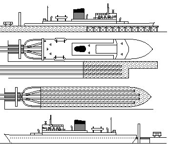
Container ships
Most ISO or European container ships are rather large, and the ports that handle them are also rather large, however there are smaller types, known as 'feeder' ships and these serve often quite small terminals on the larger rivers. The Shell Welder tanker kit from Eastern models would serve as the basis for such a ship in British N, although really a bit small it would pass muster for a home layout. The look would be considerably improved by lengthening the hull, widening the hull (requires making a new deck) would produce something quite close to acceptable. Add the container support framework to the main deck and replace the front part of the accommodation block with a taller rectangular type as shown in the illustration, this can be made using 30 thou plastic card. The rear of the kit accommodation block can be retained but you need to add a taller funnel (this can be rectangular rather than curved in shape) and you would need to add some more radar and communications gear on top of the bridge.
Fig ___ Small container ships
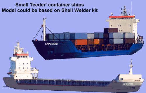
Modelling Wharfs Quays and Docks
An example of a small river-side docks incorporating most of the above features is shown below. Note that most rivers run along the bottom of valleys which they have cut through the ages, the back drop to this dock scene would therefore be rising ground, either hills (in areas where the rocks are soft) of cliffs (where the rocks are hard).
The raised platform with three small steam cranes is based on Weymouth Quay which was regularly used for imported fruit and vegetable traffic from the channel islands. Modelling these cranes is illustrated in Fig ___. The raised platform is slightly unusual and was provided because most traffic was shipped in vans. Where open wagons were the norm (such as berths handling coal) the cranes could deliver direct to the wagons and no platform would be provided. The wooden jetty is based on one at XXX which was used for handling small coastal sailing craft. On the prototype the small steam crane was fixed on a reinforced section of the jetty but adding a set of rails makes it easier to model. For details on modelling the crane see Fig ___. The grain warehouse with its raised conveyor system for loading ships is based (loosely) on a building at Wells on Sea in the South East. All the track to the left of the dock engine shed should be in-set, this includes four sets of points and as noted elsewhere the area between the wing rails will probably need to be left open.
Fig ___ River-side docks (1800-1970)

By the 1960's the steam crane on the pier would have gone and the jetty would probably never see a ship although it might still serve as temporary storage for wagons.
Note the oil terminal is intended to represent a ships fuel oil storage facility, the associated jetty is small and would be used to handle barges taking fuel out to ships at anchor. If you have room to enlarge this jetty you could make this a berth for oil tankers and liquid petroleum gas ships (you would then need to model the loading arms and etc as described above). For layouts set after about 1960 you could add a couple of spherical gas tanks (see Fig ___) and run pressurised gas tank wagons into the siding.
Fig ___ Bunker Barges
XXX Camel type and modern bunker barge XXX
Enclosed docks are better suited to layouts set in large towns such as London, Liverpool, Southampton, Leith (Edinburgh), Hull and Cardiff. If you have room you could include both river-side and tidal docks, the docks run by the Southern Railway at Southampton had both enclosed tidal docks and also a long riverside berth backed by warehouses with railway lines front and rear.
Transit sheds were used to give protection for goods being loaded or off-loaded from the ships, they were common along the quays uncommon elsewhere. Several dock companies built simple open sheds (roofed but with few or no walls) to provide protection from rain (typically wooden posts supporting timber ties with a king post roof covered in slates. Canvass sheets or simple lightweight timber walling sections were used to provide 'walls' as and when required. Iron built sheds of this type date from the first decades of the nineteenth century but timber structures were still being built at smaller docks into the early twentieth century. Typical sizes for transit sheds in moderately large docks would be 50 to 100 feet long and 20-30 feet wide. Transit sheds tended to be single storey buildings but in the later nineteenth century the transit sheds increased in size, becoming two or three stories tall to allow the use of high speed hydraulic cranes and the like. Warehouses were for storing goods and were usually set back from the quay itself. Some warehouses were placed on the quay to give direct access to the ships, these were for handling goods in bulk such as grain and secure 'bonded' warehouses for holding valuable goods (tobacco, alcohol, silk etc.).
The room required for a docks on a layout is more a matter of length than depth, one modeller built a 'docks scene' into his layout which consisted of two sidings running along a row of comparatively low structures. These buildings represented the 'transit sheds' where cargo was collated and loaded onto road or rail vehicles. The 'dock' as such on this layout was presumed to be on the far side. The plan was to use cut-out flats for the ships, slotting these in behind the buildings as required.
Using this idea with the basic 'larger industries' track plan shown in Fig ___ we can create the exchange sidings behind a large city dock complex (London's Royal docks had such a set of sidings arranged on the northern (inland) side).
Fig ___ Enclosed dock
Regarding the 'industry' on the right I would advise against making this a grain silo, grain can be unloaded on the quay directly into wagons as described above. A seed crushing factory offers some scope for unusual wagons.
The enclosed tidal docks remained in use until the 1970's, notable examples include Liverpool and London, but the increasing size of ships and the shift to containers and pallets killed them off quickly in the 1960's and 70's. By 1970 many of the older docks were largely derelict, the internal railway systems mostly closed in the 1970's and many dock companies finally give up the ghost in the early 1980's. Ships were larger and the new container ships and roll-on-roll-off ferries required specialised berths.
Not all the older ports closed completely, both Bristol and Liverpool docks have remained in use, although only a tiny proportion of the berths remain. Former small ports have grown by providing specialised handling facilities, Felixstowe on the South coast with its berths for container ships and roll-on-roll-off ferries is today one of Britain's most important ports.
A modern layout could probably find room for a simple container terminal, there is an example on the Tyne which could be modelled in a space perhaps two foot by seven inches. Immediately adjacent to the container berth is a steel works which has a small dock with a simple warehouse and on the opposite bank is an oil refinery. Re-arranging these elements provides for some interesting possibilities within a reasonable space.
^
Go to top of page