b
GANSG - Industrial ancillary structures
Ancillary Structures
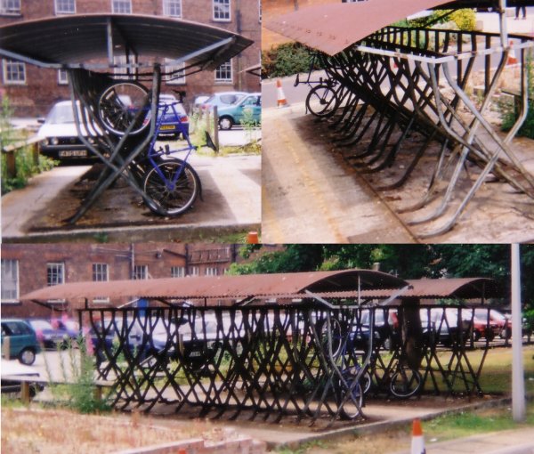
Perhaps the classic ancillary structure at any works or factory up to the 1970s was the bicycle shed, these came in all forms from a simple open fronted wooden building to purpose built structures. The example below, photographed in about 2000, was still in use at a local hospital. The framework consists of U shaped tube into which the bike wheels are resting. To keep the floor area down the bikes sit at a steep angle, as can be seen in the upper left picture. Bike sheds of this type were common in Britain from the 1920s (possibly earlier) right up to the 1970s.
Fig ___ Bike Sheds
Most industrial buildings are essentially generic, many if not most factories were bought and sold several times, being used for widely different purposes during their life. Where buildings were built to meet the needs of specific industries and supported features that identify the industry concerned, these are considered where relevant under their respective headings. Some distinctive buildings and structures were used in a range of industries and some elements of building design became generally accepted practice. One example would be the 'producer gas' building, found at many works.
Producer gas, water gas and carburated water gas (CWG) were all in essence the same thing, each providing slightly better gas than the former. To make producer gas you blow a limited amount of air up through a column of white hot coke (in a vertical metal cylinder lined with fire brick), the coke at the bottom burns producing the heat but there s then a shortage of oxygen so the upper layers of coke partially combust to produce carbon monoxide. The resulting mixture of CO and CO2 is the producer gas. Carbon monoxide will burn (if mixed with air) so this gas can be fed to burners or even used in an internal combustion engine. Water gas is similar but has superheated steam blown into it giving (amongst other things) carbon monoxide and hydrogen (more difficult to make but a better gas is produced) and carburrated water gas or CWG has an oil spray added, the petroleum oil is broken down, the lighter fractions mixing with the gas to produces even better gas (this was good enough to be used in gas lighting). All three were used in industry as the gas produced, although not as good a fuel as mains gas, was cheap to produce and could be piped to where it was needed.
The illustration below, scanned from a 1940s engineering book, shows the full CWG plant, to which would be added a separate boiler house (with its own chimney and water tank) and a tank to contain the oil used in the spray. The booster was introduced in the 1920s, prior to this the plant was preferably placed at a lower level than the equipment to be supplied. The booster pump would typically be a horizontal single cylinder steam engine with a hefty flywheel driving a large diameter cylinder reciprocating pump, by the 1930s this may well have been replaced with an electric motor driving a centrifugal pump.
Fig ___ Carburrated water gas plant
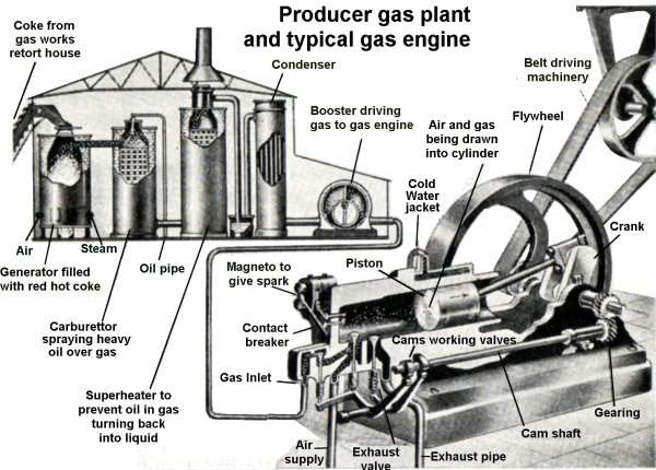
The gas is cooled down to near ambient temperature before sending it out through the pipes, this was held to be preferable although I am not sure why. From photographs I would estimate the typical size for the cylindrical structures inside the plant at four or five feet (1.2 - 1.5m) in diameter and from about eight to about twelve feet (2.4m- 3.5m) tall. At its most basic a 'producer gas' plant can be represented by a moderately large shed, usually with a metal hood sticking through the roof as shown above (a louvered roof section, as on the Peco engine shed, would do but the metal flue seems to have been a common option), with a large access door for bringing in the coke and removal of whatever ash was left. Pipes would then leave the building to carry the gas to where it was required. Having two plants in the same building meant than supplies would not be interrupted during servicing (most plants were capable of continuous operation) and large establishments would often have a bank of several gas generators.
Silos and buildings for bulk materials
Small quantities of cement, grain and other powdered or granular materials are stored in sacks. Bulk storage of these materials in silos is comparatively recent, by the early twentieth century grain silos were available at the docks but the silo for other granular materials only developed in the 1930s.
Silos can be built of wood, brick or concrete and they can be rectangular or tubular in shape. The base is often enclosed as there will be a lot of dust when it is being emptied. The base of the silo will be in the form of a hopper and there will be a system to control the discharge sticking out of the bottom.
The actual discharge could be into anything, road wagons, sacks or railway vehicles. For the rail option a common feature was a discharge pipe about a foot (30 cm) in diameter angled down from the side of the building at about forty five to sixty degrees.
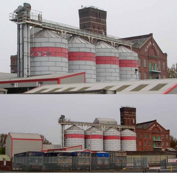
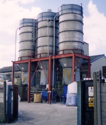
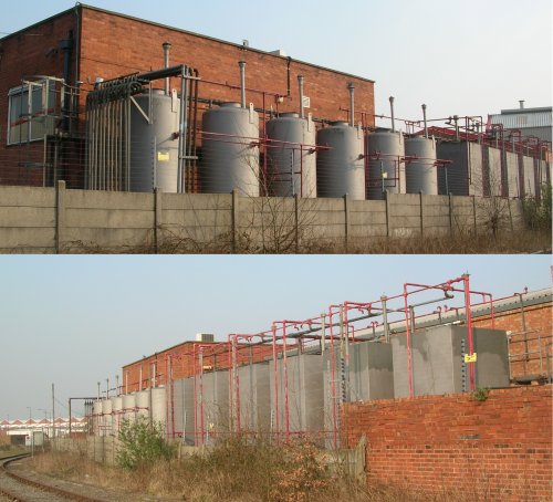
As often as not this pipe was in the open (not in a covered bay). The silos at the flour mill in the photo below can hold in excess of 500 tons of grain. This is ground to flour and shipped out in small packets for domestic use, 36 pound bags for bakeries and in bulk for larger industrial users.
Fig ___ Flour mill
The Hennebique method of construction using reinforced concrete found an early application in silo building and my father remembers visiting a concrete grain silo in Anglesey on a school trip in the mid 1930s. The silo itself was of tubular section and appeared to be made up of rings stacked on top of each other.
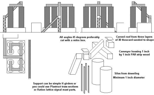
The Heljan range includes a fairly modern (post 1938 or so) concrete silo building, but with a bit of ingenuity you can make up a fairly convincing model from wooden dowel and strip.
Silos were and are used industrially for foods (mainly grain)
As discussed above powdery materials such as flour and cement were a problem prior to the development of air fluidisation. Since the late 1950s silos have become the principal method of storage for these materials.
Heavier materials such as crushed rock, coal and coke are easily and economically handled using silos and these date back to the early years of the railways. The problem here is simply one of strength and it was the early twentieth century before large storage bunkers appeared in any numbers.
Fig ___ Cement terminal
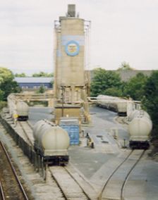
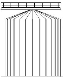
Silos are often grouped together, the sketch below shows a complex of tall silos used for China clay in the 1990s. These are easy to make and produce an impressive installation.
Fig ___ China clay silos
The example below shows a set of three storage silos at a plastics factory, the photograph was taken in the later 1980s.
Fig ___ Silos at a plastics factory
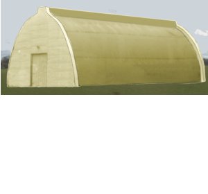
A variation on this method of storage is the modern grain/alumina storage building shown in Fig ___. Similar buildings were used for storing cement powder at cement works from the later 1930s on. These buildings were constructed in various materials and the cone shaped top was not always the same material as the supporting side walls. All-metal structures of this general type do not seem to have been used before the 1940s.
The best bet here is to use the top end of a small washing up liquid bottle cut to length depending on the application.
For the cement works the sides need to be about an half an inch to an inch high (13 mm to 25 mm) to form a low 'wall' round the base. For a cement works the base of the cone could be either brick or concrete, both are easy to model using either brick paper or a coat of light grey paint.
For a concrete top paint it light grey, for a metal top scribe panel lines into the plastic with a knife and paint it green with light grey staining. For a concrete roof paint it light grey and a tarred felt roof can be represented painting it very dark grey.
Corrugated iron is a rather more difficult proposition on this shape. Ratio corrugated sections are not suitable and home-made sheeting (discussed later) would not be ideal. One option would be to punch a number of holes through the base of the 'spout' and a similar number of holes equally spaced at the bottom edge of the cone and add thread between these. When painted up this does give the impression of some form of metal sheeting although it does not resemble any prototypical practice I know of. The grain/alumina silos date from the later 1950s and are of all-metal construction, usually with vertically ribbed sides. In British N you can get away with a simple paint job but you could cut the tube from the cone and add a winding of thread to give the ribbed side walling.
Fig ___ Cone topped storage silo
These buildings were loaded from the top via a conveyor, to make this I would suggest building a box from 30 thou card then add panels to this from 'take away' chippy metal foil tray material corrugated by squeezing it between Ratio corrugated walling sections.
Since at least the 1930s one characteristic type of building for storing powdery or granular materials has appeared. This has low side walls, perhaps four feet high, with a steeply pitched or curved roof. The powder is stored inside in a large pile on the floor and fresh stocks are usually added using a conveyor system in the roof space. When required the pile can be accessed by mechanical shovels via large end doors, or a vacuum pipe or bucket-chain device can be lowered to lift material from the pile and transfer it to a conveyor belt. These buildings are seen anywhere such powders are used in bulk, a good example being fertiliser factories.
You can make something on these lines either using Ratio corrugated sheeting to build the pitched roof type, or a ratio corrugated roof section mounted on a low wall for the curved type. For the curved type use the complete moulding trimmed at the base and paint the ends white to represent concrete. Both types usually have low side walls, perhaps five foot high, which can be represented by embossed card for brick or plain card for concrete.
The upper sketch in the illustration below was drawn from memory of a concrete building on the approach to the Seal Sands oil terminals in Middlesborough, I am not sure who owned it but I think the firm was called Tri-Oxide. Note the ends are slightly larger than the body and there is a rectangular ridge along the top of the building. I believe there was a conveyor feeding into the rear wall of the building, the doors shown being used for access by mechanical shovels for loading lorries (I could be wrong on that).
Fig ___ Buildings for powdered materials
Tanks for liquids and gasses
Many industries require the storage of bulk liquids, examples would include tar distillers processing coal or wood tars, paint works, chemical works, oil related industries & etc. There are also some uses you might not have thought of, in Trafford Park in Manchester there was a ping pong ball works which used a very large tank (originally built for fuel oil or some such) to hold a reserve store of balls to use when the plant needed to be shut down for some purpose. The example shown below is a row of smaller tanks arranged along the outer wall of a firm producing electrical insulation materials. This firm would require various types of varnish to coat the wire in transformers and electric motors. There are two tank types, the upper photo shows a row of cylindrical tanks, each fitted with a breather vent (so they hold something volatile, possibly shellac dissolved in spirit). At one end there appears to be a condenser, used to air-cool some kind of vapour and reduce it to a liquid. The rest of the tanks are plain and rectangular, note these have a fire prevention 'spray rail' arranged over them indicating the contents are flammable. Adding a set of tanks of this type along the railway side of a large building on the back scene imparts a distinctly industrial flavour to the scene in very little space. Note the building itself is quite low, roughly the height of one and a half stories of a house.
Fig ___ Tanks at an insulation works
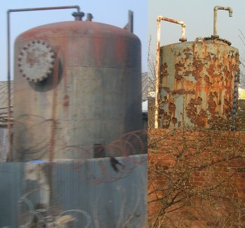
Tank design is a complicated business however tanks are ultimately just tanks and can be re-used in a number of ways. The two examples shown below both (I believe) contain fuel oil, the one on the left is still in use, the one on the right is in a rather dilapidated condition and may well be out of use. Both are about five feet in diameter and stand about twelve feet high.
Fig ___ Tanks being used for fuel oil
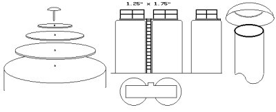
There are examples of various tanks in the continental kit ranges but you can make your own using push-off caps from aerosol containers. The difficulty is in the dome shape of the top on many tanks but there are ways round this. As an example Jiff cleaning mouse has a top 64 mm in diameter by 50 mm high (32 feet by 24 feet in British N) and the centre of the dome needs to be about 2-4 mm high. One option is to put the cap on the draining board and pour in boiling water from the kettle. Leave it to stand for about twenty seconds then (carefully) tip out the water and using the thumbs of both hands gently push the inside of the top outwards. You may need to repeat this a couple of times to get a satisfactory 'dome' but with patience the result is acceptable.
To make a rather more accurate domed top (suitable for use on a length of tubing such as drain pipe) you need to cut a set of three or four disks from 30 thou plastic card, the number and size of the disks depends on the top you have and the height of the dome. Use a set of pointed dividers to repeatedly scribe the circles on plastic card, this will eventually cut through and give you a disk of plastic with the centre marked. These are then stacked as shown below left.
If you have a suitably flat-topped drawing pin (not one of the plastic coated type) this can be used to form the top of the dome. Use the tip of a pointed modelling knife to make a small hole in the centre of each of the three larger disks and stack these on the drawing pin, adding a trace of glue to each as you do so. The resulting stack is then glued to the top of the tube. This approach keeps the discs concentric.
If you cannot find a suitable drawing pin use a length of brass wire and bend this over on the under side of the stack securing it with Milliput of Araldite. When everything is dry trim the spare wire from the top with a pair of pliers.
You now have a 'stepped' dome and you might be able to simply sand this to shape but personally I would add a coating of Milliput, smoothed in place with a wet knife blade, and when dry sand that to shape. From experience I would advise that this will require several coats of paint to hide the edges of the discs.
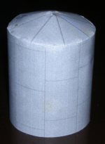
The older type of tank top, made up of triangular sections rising slightly to the top, can be made using paper. I have had success using paper printed with tank lines produced on a black and white printer (this is used for both the sides and the top). For the tank body any tube of suitable diameter that you can glue things to will do, the example shown below was based on a cardboard paper towel roll. I would suggest reinforcing the top of the tank using an inner card dome (postcard is good for this). Making this reinforcing dome is described below.
To make the tank top cut a circle of paper about 6 mm larger than the diameter of the tube. The exact size is not critical but if you are making more than one keep them all the same. Cut a line in the disk from the centre to the edge, if you slide one edge over the other the paper forms a cone shape, the bigger the overlap the taller the cone. If making several tanks mark the line where the edge falls on the paper when you have the desired height of cone. This disc can then be cut out, with the marked section removed, and used as a template for making the tops for all the tanks. For the reinforcing dome of card use the template to mark the card and remove the V shape, then push the sides together and secure with some paper glued to the inside (I used a Bulldog paper clip to hold everything until dry).
If you want flat panels, as used on some older tanks, use a protractor to measure the angle of the V shape (between the cut and the line), subtract this from 360 and divide the result by eight. This gives you the number of degrees for each panel of an eight panel top. Mark these on the card reinforcing disk, starting at the cut edge and working round the disc. Then gently score each of the lines, remove the V shape if you had not already done so and ease the sides together, gluing with a scrap of paper on the underside. I used a Bulldog clip to hold it whilst drying.
Once the card dome has set offer it up to the tube and glue in place so the point at the top is central, then trim off any excess from around the sides.
The paper top can then be added, on this part you cut radial lines into the overlap, then remove about half of the resulting tabs, gluing the rest down to the sides of the tank body. Then add a plain paper wrapper round the tank below the glued tabs, this prevents a bulge where the tabs are, and finally glue on the outer paper wrapper.
The example shown below is based on some paper towel roll with a printer paper covering produced on a laser printer. It was in the rejects box as I put the paper wrapper on the side the wrong way round, this is being re-cycled for use with toy soldiers as it will would look okay if camouflaged.
Film canisters are a handy size for oil tanks, these might be seen at a refinery in which case they would probably be light grey in colour, for other applications black is more likely. They do not have a domed top and my own attempts to use boiling water to form one have not been very successful. There is an alternative however, add a walk-way on top with an access ladder to the side. This looks good on a pair of tanks, and to keep the hand rails easy you can make it square with a short extension to one side to reach the ladder. This technique is useful for tall tanks of the kind often seen holding diesel fuel in bus and lorry depots (usually painted black and marked DERV in white on the side) as well as in various industrial applications. The sketch below centre shows the method I have used. I used 4mm scale signal ladder for the hand rails.
Short lengths tube, such as that used to sell Vitamin C tablets or Steradent tablets, can have a dome added from a ping-pong ball. Cut the ball in half, smear paint on the end of the tube and press this against the inside of the half-ball as shown below right. Cut along the resulting line and glue the dome in place. This works well for tanks of up to about half an inch or 12 mm in diameter, anything larger and the dome becomes too domed to look right.
Fig ___ Tank tops
Some industries used open topped tanks and these usually have either a walk-way or a metal frame bridge over the top to carry pipes. Depending on their contents these tanks might be under cover of some kind to prevent rain getting in, you could use the Ratio corrugated iron roof for this.
By cutting down a commercial oil storage tank you get a shorter closed tank and an open topped tank as well but the bits-box may well contain something suitable.
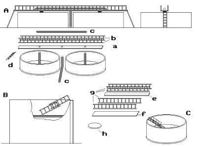
The slurry tanks illustrated in Fig ___ (A) are a good example of the general type, I made mine from small plastic containers sold with 'Earfit' ear plugs the base of which is about 40 mm in diameter and 15 mm high.
These tanks have a framework over the top carrying the feed-pipes and a rotating mechanism supported on a post from which heavy chains dangle down and stir the slurry. The framework can be made up from a 3 mm wide strip of card (a) with OO scale ladders (b) to the sides. Alternatively you can use Plastruct truss section or any lattice type sections you find in the bits box. The associated pipes (c) are from any 2mm rod, I would suggest coat hanger wire is about right. The access ladder at both ends (d) is British N signal ladder mounted at a slight angle.
Oil refineries and petrochemical plants often have what appear to be open topped tanks in the open but these actually have a floating 'lid' inside as shown in the cut-away drawing Fig ___ (B). The floating lid prevents vapour forming above the liquid in the tank and amongst other things it reduces the fire risk.
The walls of the floating lid type tank need to be about 1mm thick and the floating lid can be a flat disk of plastic card or postcard. These are actually 'pontoons' and the domed top is not noticeable. Typical sizes for tanks of this type would be thirty foot diameter by perhaps twenty five feet high (the top of a Jiff cleaning mouse tin as mentioned above would do as a basis, just wind a strip of paper or parcel tape to the outside to thicken up the walls.
The floating-top tanks usually have a telescopic walk-way leading down from the side to the centre of the tank, this can be made using strips of 20 thou card, one 3 mm wide (e) the other 4 mm wide (f), both equal to just less than the radius of the tank and each with 'handrails' (g) of 4 mm signal ladder on the sides. They are supported at the centre of the lid on a small platform (h). Place the smaller one on top of the larger and adjust them so they lie between the edge of the tank and the centre of the lid, a light wash of glue then sets the thing solid. Add a length of 'N' signal ladder to the outside of the tank to give access to the end of the walk-way. Paint the tank white, the walk-ways light grey, the ladder and hand-rails silver. Add a number to the outside (for example C12, C13 etc.) in black about 3 mm high and these end up looking rather good.
Fig ___ Open topped tanks
Tanks for pressurised liquids or gasses
The Vicks/Olbas inhaler has a 15 mm diameter cap with domed ends which serves well as the basis for an older riveted tank and for more modern welded tanks for pressurised liquids or gasses as shown in Fig ___ (A). Not all pressurised tanks have such domed ends and the body from the Peco 15' wheelbase gas tanker can be used, although this requires a little creative fettling around the 'skirt' at the base.
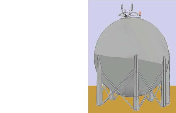
Spherical tanks made of riveted plates were in use in chemical works in the 1930s and appeared in some numbers after the Second World War. Early examples were made from individual steel sheets riveted together but by the early 1960s (possibly earlier) the engineers had worked out how to make them with a reinforced concrete shell as shown in Fig ___ (B). Spherical tanks tend to be large and are generally associated with petrochemical gasses such as ammonia, butane and propane they can be seen in factories making fertilisers from ammonia.
Spherical tanks are available in kit form but you can make them up using a smooth rubber or plastic ball, the snag is finding a suitable ball. Spherical tanks are large, in British N nothing smaller than about two inch diameter would look right. For early tanks made of welded metal plates you need to scribe in the lines of the steel plates, concrete types are easier, just a coat of white paint. Most spherical tanks seem to be devoid of markings.
The supporting legs can be round or square in section and the pipework is usually concentrated at the bottom although occasionally they are carried up to the top. In the example shown there is a platform on the top with the tank gauges (to measure the level inside the tank), emergency pressure relief valves and a warning light (on the right) for low flying aircraft. On larger modern tanks there is often only a small platform with a rectangular box on top, this houses the tank gauging equipment, the example shown dates from the early 1960s.
Fig ___ Pressurised tanks
Archimedes discovered that a spherical container will hold exactly two thirds the volume of a cylindrical tank the same height and diameter. Spherical tanks are however used to contain pressurised gasses, or liquids that would normally be gasses, so they can contain more than a non-pressurised tank of the same general size. They were at least considered for replacement gas holders at town gas works, such a tank under pressure would hold three times the equivalent volume at normal pressure for a given 'footprint' but I have found no records of such tanks being built for town gas works in Britain.
Tank enclosures
Tanks containing dangerous liquids are usually surrounded by a low wall, often of banked earth. For example oil tanks in a depot would typically have a bank around them from about three to eight feet high and about ten feet from the tank. This uses up some space but it is quite important if you are looking at an oil refinery, 'tank farm' or similar. The pipework feeding the tank does not pass through this wall, it goes over the top, supported on a metal framework and there will be stairs over the wall at intervals (typically only one set per tank). The photo below shows a tank enclosure, made for use with 00 scale toy soldiers (hence the 'destroyed' spare tanks), the chain link fencing is 'dress netting', this is slightly over scale for OO and does not look at all good in N.
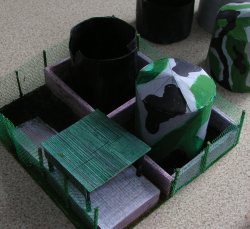
In N Gauge oil tanks made from 35mm film canisters would probably have a brick wall 6-12mm high round the tanks, with about 6mm clearance between the tank and the walls.
Representing pipework and hand rails
For pipework wire is the best bet, in British N coat-hanger wire scales out at about a foot in diameter and soft iron 'florists' wire is about five inches, steel 'rose wire' from the florists is thinner than the iron type and scales out at about three inches in British N. All of these are easy to work with and represent handy sizes for industrial pipework.
Steel Guitar strings are useful, they are made to very accurate tolerances, the higher notes are smooth wire, steel and prone to rusting if not lacquered, the lower notes are some kind of core with a wire coiled round them. They will usually be supplied in a pack of six strings but some shops sell individual strings, as a general rule the top two strings are solid, the remainder are the wound type.
The thinnest is top E for an electric 'rock' guitar and is 0.22 mm (9 thou) thick, or about one and a half inches in N, useful for grab rails and thin pipes. Next thickest is B at 0.23 mm (11 thou), these two are usually of the plain wire type and they are rigid enough for modelling purposes.
The remaining four standard strings are G at 0.4 mm (16 thou and sometimes available as a solid wire), D at 0.66 mm (26 thou), A at 0.88 mm (36 thou) and bottom E at 1.127 mm (46 thou).
The 'coil' type serve well for flexible hoses, paint them black for rubber types or silver for the metal clad 'anaconda' hoses used for refrigerated gasses and some corrosive chemicals. The largest readily available coiled wire steel string is Acoustic bottom E but this is only slightly larger than the above at 1.22 mm (50 thou). These lower notes will be the coiled type, usually the coiled outer wire is bronze and so does not rust. Some coiled strings have been ground down to give a smooth surface, others have a plastic coating, I use the cheaper non-ground type and rather than buy packs new I ask round for anyone who has a guitar to save their broken strings for me.
Quite a lot of pipes are insulated, in layouts set after the late 1940s the insulation is often covered by thin metal laid as a spiral strip. If you have a paper shredder you could shred some plain paper and use this, or you could use Lametta XXX check (long strips of coloured foil-like material used for decking out Christmas trees), although patience is required to get the wrapping even. Add the cladding after bending the wire to shape and paint with mat silver paint (perhaps with a light coat of mat varnish over the top). For short pipes carrying hot liquids or steam white asbestos lagging was the norm from the 1920s through to the 1970s. This is easy to represent using Tip-Ex correcting fluid, laid on in several coats. Once dry put some black or silver ink or paint on a length of thread and draw this round the 'lagging' to make marks which represent the straps holding it in place.
A lot of pipework ends up being buried in the ground, which makes life easier for the modeller. Often a loop of pipe is seen sticking up with a valve or a flange for connecting another pipe on the top. To represent a valve wind a strip of Sellotape round the wire and if you do not have a suitable 1mm or smaller disk just add a tiny blob of something to the top to represent the handle stem (the wheel has been removed to prevent unauthorised use).
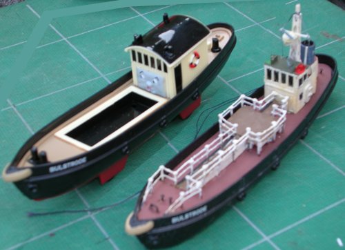
Hand rails used to be easy, Plastruct offered horizontal and stairway rails in long lengths in the ABS plastic range. These are still in the catalogue but when I asked shops to try and obtain them they were told they had to buy very large quantities indeed, making it impractical. Plastruct also offer these hand rails in their 'fineline' (polystyrene) range, however these are only sold in shorter lengths and much more expensive, so for a large industrial complex the cost can become significant. There are various ways to represent metal handrails, one of the easiest is to use Peco track pins for the posts with thin wire (eg a single strand from multi-core light electrical cable such as 'layout wire') or mono-filament nylon fishing line for the rails, however rails are visibly of-set where they are wound round the post. Mr Ahern, the creator of the Madder Valley Railway avoided this problem by soldering the wire to the pins, I did try this for one job but it was tedious work and on the plastic ship model shown below soldering was not an option. The photo shows a small tanker (actually a bunker barge for supplying lubricating oils to ships at anchor) being made up from a Thomas the Tank engine 'Bulstrode' model. The handrails on the tanker are dress making pins and the hand rails are thread, the pins and thread are thicker than ideal for N although they would be fine for OO. Note the gap in the handrails close by the accommodation block (accessed via a couple of steps from the main deck), people should not have to climb over handrails! Please note the model of the tanker was not completed when this photo was taken and the detail on the deck and 'manifold' (loading pipes on the central platform) had not been added.
Fig ___ Home made hand rails
Another option for horizontal rails is to use signal laddering glued to posts, OO scale laddering is about two feet wide in N scale which is close enough to pass muster. If using etched laddering you can super-glue or solder this to dress making pins, plastic laddering can be glued to plastic or metal supports.
Cooling towers
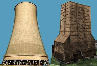
Several industries use 'cooling towers', technically called evaporative cooling towers. These are tall hollow towers with a network of pipes and a water spray system inside. These are mainly used for cooling water so it can be returned to rivers or re-used for industrial processes. The water is fed up to a set of spray pipes close to the top of the tower and falls down like rain over a series of inclined plates which delay its descent and increase the cooling effect of the air.
Modern cooling towers are wasp-waisted concrete structures and their size has increased steadily since the first was built at a Liverpool power station in 1921. The shape (actually a hyperbolic curve) is an illusion as there are no curves involved. You can obtain this shape by making two rings of fairly stiff wire and linking them with three or four stiff wire struts. Wind a long length of narrow tape between the two loops to form a tube. If you now twist one of the rings you will find you have the wasp-waisted cooling tower shape made up of many diagonal bands of tape. The wire struts should keep the two rings in alignment with the tape taut and a coating of size or even papier-mâché could then be applied and sanded smooth.
This is not suggested as a practical method for modelling such a tower, if you want one of these towers a kit is available from Heljan as part of an OO nuclear power station. The model is somewhat small and would be a satisfactory size for 2mm scale. The problem is cost and a simple and economical alternative is the wooden cooling tower.
This is a tall four sided structure with an open top, made up of vertical planking with a heavy external wooden frame and usually an overall dark brownish grey colour. There was an example at the Burnt Island aluminium plant near Edinburgh that remained in use into the 1990s, only being demolished in 2003. Other examples were in use into the late 1950s at Monkton colliery (actually at the coking and chemical plant) and there was a set of three similar towers behind Beckton railway station in the London area. I have no idea what the factory at Beckton produced but there was a large gas works in that general area, the place name comes from the gas works, the site was so named in honour of Simon Adams Beck, the Governor of the Gas Light and Coke Company, which built the river side works in 1870. By 1879 the company were seling coal tar and ammonia and after World War One expanded into the full range of tar derived chemicals. The Beckton towers were connected to a number of large, three foot diameter plain metal pipes, at least one of which was carried over the railway line to some installation or other on the opposite side.
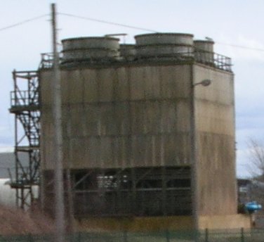
Both types of tower require a lot of ventilation at the base, on the concrete type this is achieved by supporting it on a series of concrete posts (below left, note these things are big, the apparent 'lean' is an artifact of the very wide angle lens used for the photo), the wooden type have slats running round the base (below right, this was one of a set of four closely spaced towers).
Fig ___ Concrete and Wooden cooling towers
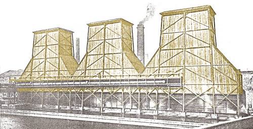
I was fortunate to be in contact with Mr. David Bowie, who is something of an expert on these matters and he was able to provide a number of illustrations. The example shown below was built for Bradford Corporation at their electricity generating station. Mr Bowie advised that these were the Valley Road Bradford Davenport Towers, a set of three circa 75,000 gallon per hour towers arranged over a common cooling pond at the former Bradford Corporation Valley Road Power Station, (this was adjacent to the main railway line to Bradford Foster Square station). Mr Bowie estimated the height to be in the order of 140' high, with a base size of some 90' x 41'. Since the height is very much extended in comparison to the area of the base, these proportions are fundamentally different from all of the other Davenport "Bradford" towers. This must have been principally concerned with mist dispersion.
Fig ___ Wooden cooling towers at Bradford
Mr Bowie was also able to advise:
As promised, some information on British wooden cooling towers.
There appears to have been two main manufacturers of wooden natural draught
cooling towers in the UK: (i) The Davenport Engineering Co., Ltd., Harris
Street, Bradford, (Telegrams: "Humidity, Bradford"), and; (ii) The Premier
Cooler and Engineering Company. Since the dimensions and constructional
details of these towers are essentially identical, I quite strongly suspect
that these companies may have been one and the same.
The Davenport company produced towers in the 'Bradford' range.
These towers
generally were 70' high, with the overall dimensions of the base being
selected from a standard series of sizes as dictated by the semi-modular
build to arrive at the required capacity. Thus, a nominal 100,000 gallons
per hour tower (capable of reducing this quantity of water from 115degF to
75degF) was a type 'T1224'. This designator indicates that there were 12
main posts and that these were on 24 feet wide centres. The corresponding
overall dimensions being 87' long x 24' wide x 70' high.
Similarly, a 200,000 gallon tower was a type 'T1437', indicating 14-posts on
37' centres, for overall dimensions 103' x 37' x 70', and a 300,000 gallon
per hour tower was designated type 'T1441, for 14-posts on 41' centres; 108'
x 41' x 70' overall.
The main upright posts were typically 8" x 8" timbers in Pensacola Pitch
Pine, scarf jointed at mid-height and secured with galvanised fishplates.
Horizontal and diagonal bracing was also in pitch pine, typically 4" x 4".
The horizontal members were arranged 12' to 13' apart over the height of the
chimney tower.
Cladding boards were of 6" x 1" Swedish Red Wood, tongued and
grooved and arranged vertically. A substantial cornice, some 2'-10" high
surmounted the tower. With the exception of the wetted areas, all timbers
employed in the construction of the tower were pressure impregnated with
creosote. All metal fittings, bolts, and nails were heavily galvanised.
When viewed from above, there was a series of horizontal cross braces on the
same centres as the main vertical posts spanning the width of the tower and
so supporting the side walls.
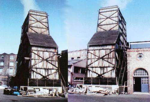
The photo below shows a Premier tower at Paton & Baldwins woollen mill,
Alloa, Scotland. This was photographed in 1976, and has since been demolished.
Fig ___ Wooden cooling tower at Paton & Baldwins, Alloa
The height of the tower dictated the available draught and the base size
stipulated the arrangement of the water distributors and total number of
spray nozzles, hence throughput of water. The water was introduced to the
towers via one main feed header of around 18" diameter positioned centrally
on the length or width of the tower some 20' above the base. This header
supplied a series of branch pipes constructed in asbestos cement jointed
with cast iron muff couplings into which numerous brass sprayers were set.
The spray nozzles were designed to be most effective over quite a narrow
range of pressure, so these towers were fairly precisely designed for a
given duty. The water spray cascaded down over a set of wooden laths of
square section, arranged with their diamond points uppermost. This whole
arrangement of water distributors and cooling laths was supported from piers
in the water collecting tank positioned below the tower, as such it was
structurally separate from the chimney tower proper.
The bottom 12' of the
tower, where the air entered, was louvered (horizontally) around the towers'
entire perimeter. The bundle of cooling laths was contained within the
bottom boarded section of the tower. Therefore, when looking through the
louvered section, one saw only the vertical posts supporting the bundle of
laths. All of these constructional details were subject of patent in their
day.
A door way, accessible by a substantial fixed inclined wooden staircase with
4" x 4" handrails and top landing gallery, was set in one side of the tower.
This gave access to an internal walkway from which the water distribution
pipework and spray nozzles could be subject to performance checks and
maintenance.
The tank bases of the towers were in reinforced concrete, with the main
structural posts being supported from the sill of these tanks. The tanks (in
effect ponds) generally sat above the surrounding ground area, although in
some instances the tank was excavated below grade level. The tank water
outlets -- one in number in smaller towers, two in the larger sizes --
penetrated through the concrete walls. Adjoining the tanks would be large
bore feed and return pipe lines, typically up to 2' in diameter. These would
be fitted with heavy cast iron bodied gate valves, accessible from various
catwalks and access platforms.
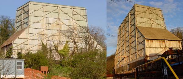
The photos below show the 300,000 gallon per hour Davenport cooling tower at the
former British Aluminium (Alcan Chemicals) alumina plant at Burntisland in
Fife. Believed, until demolition in 2003, to be the last surviving wooden
cooling tower in the country. This tower was originally built in 1937, the photo was taken after decomissioning and some sort of sheet material has been nailed on over the vents at the base (visible below right).
Fig ___ Wooden cooling tower at Alcan, Burntisland
These wooden towers were seen at a wide range of industrial locations, including power stations, coke plants, foundries, dairies and various other industries with a requirement for cooling water or gasses after processing. Power stations in particular would often have quite a few of the wooden type of tower, later often replaced by a few much larger concrete types.
There are however problems with this approach to cooling, mainly the dispersal of a fine aerosol mist of water droplets across the site, which might contain bacterial contamination (since the 1980s Legionaries Disease has been a constant worry). As a result the towers require careful treatment prior to commissioning and throughout their operating life. In general cooling towers always require chlorination after installation and prior to being brought on line with the associated maintenance water treatment dosing. In addition chlorinations are required twice per annum and additionally when work is conducted on the tower pipework or when the tower has been shut down.
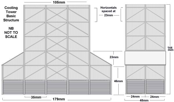
From Mr Bowie's information we can construct some basic details for building a model of one of these towers. The figures quoted are for British N Gauge with OO gauge in brackets (although a degree of compression might be desirable at the larger scale).
The smaller type 'T1224' towers are 87' long x 24' wide x 70' high. At 1:148 (and 1:76) that corresponds to 179mm (349mm) long, 48mm (94mm) wide and 144mm (281mm) high. For those more comfortable with older units it works out at just over five and a half inches long, close to 2 inches wide and five and three quarter inches tall in N gauge (about double that for OO).
Hence in N you need two pieces of card 144mm tall by 87mm wide with 1mm scribed lines running up the longer dimension for the sides. You also need to pieces 144mm tall by 48mm wide for the inner ends and two pieces 46mm tall and 48mm wide for the outer ends, again with the plank lines running vertically. The top of the tower is 105mm wide. The base section is 46mm high at the outside, rising to 69mm.
In N Gauge the 4 inch horizontal and diagonal bracing can be represented fairly well using 30x30 thou strip, the horizontals should run at 23mm intervals from the base to the top. This leaves a section at the top for the cornice. The 8 inch vertical posts would be 60x60 thou strip at 35mm centres.
Fig ___ Basic dimensions for small wooden cooling tower (N Gauge)
Draw the sides and ends on 1mm scribed plastic card with pencil, marking the centre lines for the horizontal and vertical bracing (you can add the diagonals but this should not be needed as they run from where the horizontal's and verticals cross). Cut out the sides and ends (personally I would extend the inner pair of ends right to the base to strengthen the structure). For the vents at the base you would probably get away with using OO scale corrugated card sheet glued directly to the lower sides, once the tower is completed and painted run a fine tipped fibre tipped black pen into the indented parts to represent the openings into the base. Lay up the horizontal and diagonal bracing from 30x30 thou strip then add the verticals on the outside of this (daylight is visible behind the verticals at the corners in the photographs). As I remember it Slaters corrugated card is slightly over 30 thou thick, so you may need to either sand channels for the bottom of the verticals, or sand the verticals where they cross the vents.
You now add the final details, firstly add the roof to the outer wings at the base, I believe this was usually corrugated iron (Slaters plastic card would serve well) but it might equally be tarred felt, for which paper parcel tape laid onto plastic card serves well. You need to add a 3mm diameter 'pipe' feeding in to the tower and a doorway with access ladder or (perferably) stairs. 3mm diameter wire is not commonplace but you can use round electrical flex for the pipe. On some towers the pipe came some distance, supported on columns, then ran along the side of the tower on a walk-way (as on the Bradfors towers shown above), on others it seems to have run underground, rising up to the side of the tower about three feet out (to allow for the bend). The latter is the easy option (see the picture of the Alcan tower above).
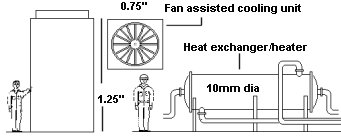
Since the late 1950s the fan-assisted cooling tower has been a regular feature of many industries. The most efficient types employ Adiabatic cooling and have the advantage that the water can be contained in pipework and hence does not generate the aerosol mist so no chlorination is required. These have a fan mounted near the top to draw air over an internal network of pipes and/or radiators. An example is illustrated in Fig ___ below, these can be seen in one's or in groups of two, four or even six units. The photo shows a large four-fan unit at the Brunner Mond (formerly ICI) plant at Northwich in Cheshire. The scale can be gauged from the handrail round the top of the unit.
Fig ___ Fan assisted cooling towers
The fan blades are usually mounted quite close to the top of the cylindrical extension and they rotate at variable speeds depending on the load. Model ship propellers could be used for the fan but motorising them would require gearing to get the right speed (about 60-200 RPM).
One final unit which can be modelled is the heat exchanger, the example below formed part of an LPG (Liquid Petroleum Gas) plant. The chilled liquid gas is fed in at the bottom of the main body and emerges at the top. The body contains a series of pipes, arranged very much like those in a railway locomotive boiler, open at either end into the domed cover. Warm water is pumped in at one end, passes though the pipes and emerges at the other. The domed covers are removable so that if one of the through-pipes develops a leak it can be sealed with plugs at each end as a temporary repair. This unit is used to warm the gas which had been stored as a chilled liquid so that it can be pumped into pressurised storage tanks for loading into pressurised railway wagons or road tankers. Similar units are used in a number of chemical processes.
Fig ___ Fan type cooling tower & heat exchanger
Note that some single flue fan assisted towers are actually 'power assisted' chimneys which are used to push noxious fumes higher into the air to reduce local pollution. These are sometimes added to older chimneys when the latter need expensive repairs or where they were not throwing the fumes high enough to meet modern regulations. They are not very common however and offer little additional potential from a modelling perspective.
Kilns
Kilns are basically industrial ovens (i.e. the heat is contained within the structure), however the term is generic and there were several designs, each distinctly different in appearance. Large kilns are used for pottery and clay goods such as bricks and tiles, they were also used for cooking limestone to produce lime. There are a few important kiln types which saw general application, the older 'bottle', 'beehive' and 'scotch' kilns and the more recent downdraught and tunnel kilns, particularly the Hoffman type.
The development of brick or stone built kilns for making bricks, in which the hot air could circulate round the stacks of brick inside, produced a much better product than the older method of piling coal around the bricks and covering the lot with turf before setting fire to the coal. The Scotch kiln is the most simple type and was widely used for brick making. There is a wall with arched entrances set into it (via which the fires are lit) and large openings at either end (used for loading in the material to be cooked), the top is open and was covered with turf before firing. Scotch kilns were widely used for brick making but also seen in limestone quarries producing lime, the bricks or limestone were piled inside the kiln, sitting on a layer of coal, with layers of coal added if the pile was high or the coal of poor quality. Once loaded the ends are sealed and the coal is set light (the side openings then being closed with metal doors to control the air flow), little monitoring is required, once all the coal is burned the kiln is opened and the product removed. I believe Scotch kilns were also built with a fixed arched brick roof, converting them into a form of tunnel kiln (discussed below).
Fig ___ Scotch Kiln
Bottle kilns are normally associated with pottery but they were also used for making early forms of cement and at least one brick works had a kiln of this type. A bottle kiln and the related shorter 'biscuit kilns' (used in pottery manufacture) consist of an inner and outer structure all built of brick. Early types were often built as a straight sided cone as shown below, later types incorporated a gentle curve at the 'shoulders' of the kiln which served to reflect the heat back down onto the material inside. This later type was the most common, in the potteries of Staffordshire there were many hundreds of these in the towns.
Fig ___ Bottle kiln
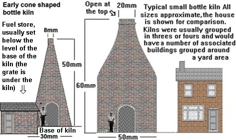
The visible 'bottle kiln' is in fact an outer shell, the kiln itself was a similarly shaped structure built inside with perhaps four foot clearance between the two shells. The entrance was about seven foot high by five foot wide, coal went in in wheel barrows and the pottery went in in large fire clay trays or basins (perhaps three foot by two foot by a foot or so high) called 'saggars'. The saggars were lined with some crushed flint to prevent the pots sticking to them, once filled they were stacked up inside the kiln and the fires were lit. Even with the flint dust lining the new pots tended to stick to the bottom of the saggars and there was an actual job title of 'saggar makers bottom knocker'. This chap was employed to hit the bottom of each saggar as it was lifted out of the kiln. He used a wooden implement to break away the plates, cups or jugs inside, some skill being required to do this without breaking the saggar or the new pots themselves.
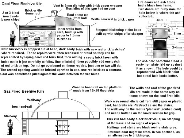
The beehive design shown below was a common choice for smaller brick and tile works had a range of uses from brick making to converting coal into coke (prior to the widespread introduction of the coke ovens developed in Belgium as described in the section on Gas Works, Coke and Smokeless Fuels), whilst the scotch kiln was mainly associated with brick and tile making.
The beehive type were 'downdraught' kilns, they have a series of holes in the floor connecting to a chimney located close by, often rectangular and typically only about twenty to twenty five feet high and often serving for several kilns. The goods to be fired are stacked inside and the entrance is bricked up. The kiln could be fired using coal (the kiln having a series of fore ports located around the outside), oil or gas (both piped into the kiln). The hot gassed rise up to the roof then pass down through the goods and out via the holes in the floor to the flue. When used for bricks this type of kiln would be fired for several days, the temperatures obtained were high and produced very strong bricks.
Fig ___ Beehive kilns
Beehive kilns remained in use at smaller works for brickmaking and even for coke production into the 1950s but larger brick and coke works switched to more efficient designs as described below.
All of the above are batch kilns, the thing was set up, the fires were lit and after a set time the fires were extinguished and the contents allowed to cool. This works but it wastes a lot of the heat, which adds to the expense of the finished product.
To save money on fuel you can feed the material to be cooked through a continuously operating kiln in which the chamber is kept hot and the material passes through either on trucks or by gravity. This presents a range of technical challenges however and an alternative approach is to use the waste heat exhausted from one batch to pre-heat a second batch. This simple idea lead to the development of the 'tunnel kiln' in the mid nineteenth century. The tunnel kiln consists of a number of chambers arranged so the hot flue gasses from one chamber are drawn off and used to heat the following chambers before being passed to the chimney.
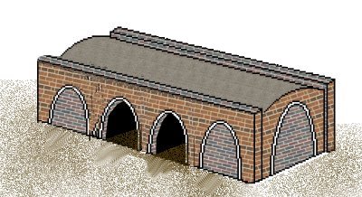
The most simple type of tunnel kiln is shown below, it resembles the simple Scotch kiln but it actually a downdraught type which would have a separate tall chimney (possibly serving several kilns). It has large openings at each end and a series of smaller openings along the sides in which the fire was set, there is a set of baffles built into the building to control the air flow. The sides had a slight slope to them and there was a 'hump' following the line of the central tunnel along the top of the structure. The bricks or whatever were piled up in the central tunnel and walls were built up to either side to form a chamber. Coal was then burnt in the side entrances and the hot gasses were directed through the stack of bricks. The example shown is a 'downdraught' type which would have openings in the floor leading to flues and an associated chimney. This 'simple' type shown below is sketched from a photo, in practice you can get away with a lot less on top of the kiln, a simple chain running along the tops of the side girders is all that is really required.
Fig ___ Simple tunnel kiln
A good example of a small kiln can be seen as part of a brick works on John Ahern's Madder Valley Railway at Pendon Museum. Unfortunately this was added after he wrote his famous books on landscape and building construction (see bibliography) and so its construction is not described and I am not sure if it is a tunnel or Scotch type (although I believe it is the former).
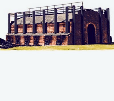
The most popular form of tunnel kiln is the Hoffman kiln, dating from the 1860s and these have remained in use into the 1990's. Hoffman kilns consist of a mound of earth (or a thick central brick wall) with a brick built tunnel running round the outside forming a continuous run. The tunnel sides sloped outward at the bottom and there were entrances at intervals, typically every ten or twelve feet. The section of tunnel between the entrances constitutes a chamber.
In the top of the tunnel were a series of holes, large ones for feeding in coal and smaller ones for controlling air flow down into the chambers. These were covered by a simple building, often made of corrugated iron sheeting and with a centrally mounted tall chimney. The kiln itself is of the down draught type, the hot gasses exhaust via holes in the floor into flues leading to the central chimney. The coal was either hauled up an incline or lifted by a powered hoist in small tubs. It was common practice to maintain a small stockpile of coal although regular deliveries were made, usually by rail.
Hoffman kilns were used for several purposes, the most important however were making bricks and making lime. The bricks or lumps of limestone were piled up in the tunnel, in the space between two entrances, and the tunnel was then blocked to either side with a brick wall to form a chamber. Holes were left in the wall leading to the next chamber. Coal was added through the roof holes of the first chamber and set alight, meanwhile the next chamber was being filled with bricks or limestone.
Steel doors were fitted over the entrance between the two stacks and sealed with fire clay (at some brick works the entrances were bricked up). The airflow from the first chamber was then adjusted using dampers fitted to the chimney and coal holes so the hot smoke from the first stack passed through the second, pre-heating it.
Again the following section was being filled with brick or stone and coal was poured in to the second stack and set alight.
This process continued along the tunnel and by the time they got back to the first stack of bricks the fire in that chamber had gone out, the material inside had cooled and had been replaced by a fresh load for firing.
The kiln could therefore run continuously and when repairs were occasionally required to the brick lining of the tunnel these could be done without shutting down the whole plant.
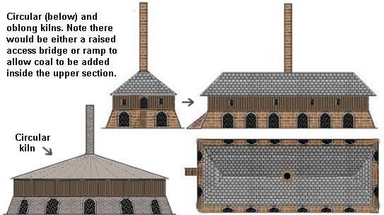
The first Hoffman type kiln in Britain was probably a circular type, built for the Nottingham Patent Brick Co in 1861, and circular examples survived in use into the 1970s and possibly the early 1980s. In the 1870s however a revised design appeared based on an oval shaped building, still with the chimney in the centre. These oval designs offered long tunnels without having to build a huge central raised mound, they had curved, usually semi-circular, ends but the roof of the upper part might well be square, supported on H section columns in the corners. On larger kilns there would be a couple of entrances on each end, in smaller kilns they were only along the sides.
Fig ___ Hoffman kiln
This may all seem rather labour intensive, which it was, but the bricks were still largely man-handled into the kilns, then from the kilns to the stock-pile and onto the lorries and railway wagons. This mitigated against mechanisation as the equipment cost money and the labour force would simply end up with free time.
In the old coal or gas beehive kilns the fires were kept burning for about two days to 'fire' the clay. Coal and gas fired kilns of this type remained in use at small brick works into at least the 1950's and some small firms were still using scotch kilns in the mid 1990's. In the 1930's some kilns were supplied with 'producer gas' burners and more recently (since the latter 1960's) gas supplied from the mains has been used.
In America mechanisation has always been favoured and in about the 1880's they started building 'linear tunnel kilns' in which the bricks are placed on steel trolleys and carried through a series of heated chambers at progressively higher temperatures. The theory behind the linear tunnel kiln suggested they should offer advantages but early designs were not a great success and they did not become popular in Britain until after the Second World War. A modern linear kiln can consist of over 150 different chambers through which the bricks pass on metal trolleys. As one lot of bricks were removed from one end another lot were being wheeled in at the other. The heated air from the cooling bricks at the output end is fed into the earlier stages to pre-heat the bricks passing through. A typical kiln might be 30 or 50 yards long, often these were semicircular in section. A simple representation of an early linear kiln can be produced using a length of half round section wood, perhaps 20 mm across the flat, with a covering of brick paper and plasticard doors added at either end. There would be a small square structures with chimneys at intervals along the side where the fires were set, these would house the controls for the gas burners, coal firing would be unlikely).
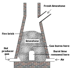
Truck systems are comparatively recent, appearing in brick works in the late 1940s, but gravity feed systems date from the late nineteenth century and are still in widespread use today. Gravity fed kilns are of no use for materials such as tiles and bricks but cement makers have always favoured gravity feed. Early cement works favoured vertical 'shaft kilns' which consist of a heat resistant tube, often buried in the ground, with a grate at the bottom. Coke is laid on the grate and a layer of the material to be burned is added by feeding it in at the top. More layers of coke and material are added through the top and the coke at the bottom is lit. As the coke burns away the burned material falls down through the grate and is removed, meanwhile the fresh supplies of alternate layers of fuel and rock can be added at the top of the stack and they are pre-heated by the hot gasses rising from below. By controlling the air flow the area where the main heating of the material took place was held at about the half way point in the kiln. The air was allowed in at the bottom of the shaft and the hot gasses exhausted at the top, the material above the burning point was therefore pre-heated by the hot gasses whilst the burnt material at the bottom was cooled by the air flowing into the kiln.
Vertical kilns were widely used for lime burning (where limestone is heated to produce lime powder) and the buried type offer a minimum space option for modelling. Lime kilns are a lot shorter than cement kilns and were often built into a raised bank or hill side. There was a lot of demand for lime in most areas of the country for both building and for spreading on agricultural land. Coal tar distillers, already producing copious amounts of smelly smoke, sometimes had a lime kiln on site to make the lime they required for processing the tar.
Most lime kilns were rather squat affairs, two or three kilns would be a typical compliment for a quarry but there were single kilns dotted about, usually associated with producing agricultural lime for local consumption. Larger quarries featured larger kilns, often of the Hoffman type, an example of which is illustrated in the section on Quarries. By the 1930s producer gas was commonly used to fire lime kilns, the section below shows a typical arrangement for a fairly modern design. This type would have an outer metal case and is fed with producer gas, a sketch of a very large version of such a kiln (based on a photograph) is included in the section on Open Cast Mines & Quarries.
Fig ___ Cross section of a vertical type lime kiln
Earlier examples of lime kilns were built of stone or brick (with a fire brick lining), some were then clad in cement or concrete. Some had entrances on three sides (called 'three draw kilns'), others had an opening at the base on one side only (single draw kilns). The sketch below is typical of the general type, depending upon the local demand there might be several such kilns arranged side by side. Where a convenient hill was not available an inclined plane on a side tower equipped with a hoist is required.
Fig ___ Typical lime kiln
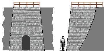
Not all kilns were the square pyramidical section, rural kilns, usually smaller single draw types, were sometimes round and buried more deeply into the hillside, often built of rough stone and distinctly 'rustic' these are of no real interest in the present context.
Limestone is calcium carbonate CaCO3, to get lime you heat this in a furnace to over 900 deg c where the carbon and some of the oxygen is driven off as carbon dioxide to leave Calcium Oxide, CaO, known as 'quicklime. If you add water to quicklime you get slaked lime, calcium hydroxide Ca(OH)2. Slaked lime mixed with water and sand is mortar, the lime reacts with CO2 in air in air to form calcium carbonate. Cement is made by roasting Calcium Carbonate, clay and coke and ends up as a mix of calcium silicate and calcium aluminate, this sets hard when mixed with water and will set under water (unlike mortar).
Vertical kilns were replaced in cement manufacture by the rotating type which consists of a metal tube with teeth inside supported at an angle. The materials to be burned are fed in at the top and burning coal dust or gas is blown in near the bottom. As the tube rotates the material makes its way down the tube being mixed by the teeth and fused into a clinker by the burning goal or gas. There is a cool section near the bottom end where the material cools to a sensible handling temperature before it emerges whilst the teeth break up the larger lumps that have formed. Modelling the rotary cement kiln is described in the section on cement works.
Smelting (blast furnaces and reverbatory furnaces)
Separating metals from their ores is called smelting and this requires rather more heat than is obtained in a kiln. You can increase the heat of a fire by forcing air (and therefore oxygen) into it using bellows and the blast furnace (originally developed in Belgium in the fifteenth century it was soon imported into Britain) is usually used for this work. A blast furnace consists of a stout tower with a blast of air fed in at the bottom supplied from bellows or fans. In older works the bellows were powered by water wheels but by the mid nineteenth century steam powered bellows and fans were becoming standard. The ore and fuel are mixed and poured in at the top usually with additional material to absorb or combine with various impurities in the ore. At the bottom the heat rises to over a thousand degrees and the metal melts, forming a pool in a specially shaped heat-resistant container or crucible in the base of the furnace. The unwanted impurities form a scum or 'slag' on the surface and the fuel burns away any oxygen in the ore. The wanted metal and the slag are tapped off through different openings in the crucible at the base.
Early blast furnaces used charcoal as the fuel which meant that the forests were soon depleted. Charcoal is made by heating wood without any air to drive off everything but the basic carbon, coke is made in a similar way but starting with coal. Trees were becoming scarce and paws were passed restricting the making of charcoal, this pushed up the price of iron. In 1709 Abraham Darby the First discovered he could use coke (made for a local maltings) for smelting iron ore. This allowed the whole process to be scaled up and saw the rapid relocation of iron works from forest areas to the coal fields of south Staffordshire, South Wales and south Yorkshire.
The last charcoal fired blast furnace in the Wealds closed in 1813 and the very last charcoal fired blast furnace in the country closed in 1923 but these are of less interest in the present context as they were often not directly rail connected.
The original blast furnaces were rectangular and built of stone and it was common practice to build these furnaces on a hillside where a simple bridge could be provided to carry the tubs of ore and other materials to be tipped in. Note that building a new blast furnace is expensive, it requires land, time and money. The original rectangular type of blast furnace with its gasses venting from the top or simply directing them off to a flare tower (a big chimney with flames at the top) remained in use into the early twentieth century, especially in areas where the industry was not doing well.
If the air being blown in to a furnace is pre-heated the temperature inside the furnace rises dramatically and in 1828 a Glasgow iron maker by the name of Nielson began pre-heating the air blast with a separate coke fire. Early blast furnaces were simple open-topped towers, the hot gasses were allowed to escape from the top, wasting a lot of the expensive heat.
There are two ways of using the waste heat to pre-heat the blast air, called the regenerative and recuperative systems. The recuperative system uses a heat exchanger to extract heat from waste gas and pass it to the blast air. The heat exchanger typically consists of a set of flues separated by thin walls of some heat conducting material, usually high temperature clay (or 'refractory'). The waste heat in the exhaust gasses passes through these thin walls to heat the incoming air. This type of arrangement was favoured by gas works and other processes where the volume and temperatures were comparatively low.
The regenerative approach was invented by Frederick Siemens in 1856 for use with steel making in the 'open hearth process'. The system employs two chimneys, each connected to a chamber full of heat resistant bricks stacked in an open honeycomb. The blast air is fed though one chamber whilst the hot exhaust gasses are passed through the second, heating up the bricks. When the fire bricks in the exhaust chamber are hot the air and waste gas lines are changed over, the waste gas then heats the bricks in the second chamber whilst the incoming air is heated in the first chamber. The flow is alternated through the two chambers and a considerable saving in fuel is affected.
In the 1850s an engineer called George Parry devised a valve for the top of blast furnaces consisting of a bell shape which could be lowered to allow fuel into the furnace or hoisted up to force the exhaust gasses out through a side-mounted pipe and thence to a set of regenerative ovens.
The exhaust gasses from a blast furnace are often flammable (usually there is quite a lot of carbon monoxide in them) and in 1857 a man called Cowper came up with the idea of using the exhaust gasses to fire a set of ovens which pre-heat the air to be blasted in to the furnace. The first Cowper type furnace was built in 1860 and this soon became the standard design for new furnaces, especially those for smelting iron ore.
To trap all the exhaust gasses Cowper's furnace has a cap on the top of the furnace with two bell or cone shaped plugs arranged one above the other. The top plug is lowered to allow the charge of coke, ore and limestone to be poured in. The top cone is then pulled shut and the lower cone is eased down to allow the charge into the furnace. This means the exhaust gasses cannot escape from the top and they are forced through an arrangement of big pipes to the pre-heating ovens. This type of furnace has remained the mainstay of the iron and steel industries to the present day.
The problem with using blast furnace gases is that they are full of dust and soot which need to be removed or they will clog up the ovens. Removing the dust was usually done by fitting a short length of large diameter pipe in which the gasses slow down and the dust and detritus falls out of the flow to collect in the bottom.
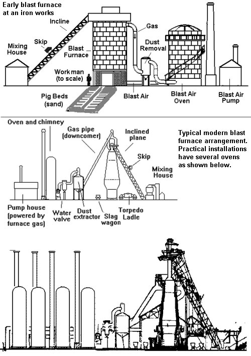
In the mid nineteenth century a new design emerged consisting of a boiler plate shell lined with heat resistant fire brick. These were tall towers typically 100 feet high and where a convenient hillside was not available there would be an inclined track carrying a skip which tipped the ore and other materials in at the top. These furnaces in turn increased in size and evolved into a tapered tubular shape not dissimilar to the early rectangular structures albeit much larger. Modern furnaces are typically 100 feet (30m) tall and 30 feet (9m) diameter at the base, definitely candidates for the back scene. The distinctive pipes and furnaces of the Cowper design blast furnace on the horizon will serve identify an iron or steel works on the layout.
Fig ___ Blast Furnaces
Blast furnaces with minor differences were used for smelting lead and a sketch of a typical installation dating from about the 1920s has been included in the relevant section (see Fig ___).
The blast furnace mixes the fuel with the minerals and this can lead to problems of contamination, the reverbatory furnace solves this problem by separating the fuel from the material being heated. The temperatures reached are nearly as high as a blast furnace and reverbatory furnaces were used for recovering metals of a lower melting point. Typically there is a low wall separating the fuel side from the crucible side with a domed roof over the assembly. The hot gasses from the fuel pass over the surface of the material in the crucible side and more heat is reflected from the domed roof. Most of these furnaces were more or less rectangular, although some were more circular in plan.
Fig ___ Cross section of a reverbatory furnace
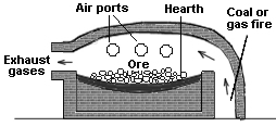
This is really a high temperature version of the bottle and beehive kilns described above.
Weigh-bridges and weighing machines
A weigh-bridge is a very large set of balance scales used for weighing large vehicles, including horse drawn carts, lorries and railway wagons. The first practical machines of this type were invented by John Wyatt of Birmingham in the 1740s and the external appearance then changed little until the 1960s. The typical installation for road vehicles consists of a large metal plate set into the road surface with a small hut beside it containing the scale. The works are all underneath the plate and need not concern the modeller however the basic arrangement is shown below, one point to note is that the timber or metal covering the link between the bridge and the hut should always be aligned with the centre of the bridge
Fig___ Weighbridge mechanism
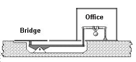
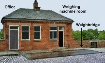
The weighbridge was a feature of most railway goods yards, kit's are available from various sources some of which come with an etched brass bridge. The picture below shows a variation on the basic design, a large building is associated with a weighbridge but only the right hand third of the building houses the weighing mechanism. The remainder is a large office as this example was on a road leading to a small group of factories and a canal wharf and warehouse. Note that the plate covering the linkage between the bridge and the weighing room is located under the window, in the centre of the bridge not the centre of the building.
Fig___ Weighbridge with attached office
Road vehicle weigh bridges are associated with bulk materials handling, minerals such as coal and iron or and goods such as grain. Bulk liquids also require weigh bridge facilities but this depends to some extent on who is operating the depot and where the goods are going to and from.
Since the 1960s other types have come into use, one easily modelled modern type looks like a low bridge, built entirely of concrete. The sketch below is based on an example at the former rail-served Blue Circle cement depot at Northenden, south of Manchester. The photos were taken in the late 1980's from a passing train and show no office immediately beside the bridge, presumably there was some form of remote reading facility in a nearby office. The bridge was located on the approach road leading to the terminal and there was room for a lorry to pass clear of the bridge when required. The deck of the bridge was large enough to carry an articulated cement lorry and semi-trailer.
Fig ___ Modern Weigh-bridge
The bridge itself consists of a raised base approached by two ramps with mow concrete walls to either side. The photograph below shows the entire terminal, the bridge is located in the centre between the two diverging sidings. It has two oil stains on it and the sides of the base, where the lorry runs, are a slightly different colour.
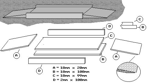
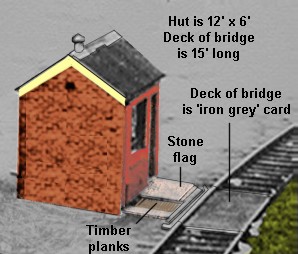
The railway wagon weigh-bridge uses an essentially similar mechanism with a platform and a small hut close by. The platform was usually covered with planking and can be easily modelled as shown below. The associated hut can be a normal brick or concrete type but in some locations this is set into the ground. This latter design is associated with hopper wagon loading points, it allows the weigh-bridge staff to check that hopper doors are closed as the loaded wagons are drawn over the bridge. Railway wagons had their tare (empty) weight marked on the side so it was only necessary to weigh the loaded vehicles, in the less regulated world of road haulage it was normal practice to weigh the wagon or cart as it went in and again when it came out to confirm the markings were correct.
The example sketched below was in a welsh goods yard, it was situated on a siding feeding the end loading dock and running past the heavier of two yard cranes. This meant not all wagons were weighed but those most likely to carry heavy loads would pass over it. I think the coal sidings branched off from this line, so it may have been used for the coal wagons, although I am not sure why the railway would wish to weigh loaded coal wagons arriving in the yard.
Fig___ Rail Weighbridge
On older rail weigh-bridges each wagon had to be positioned on the bridge in turn. Modern rail weigh-bridges, built since the later 1960s and where the traffic is constant, have been engineered to allow the wagons to be pulled over the bridge in a rake.
^
Go to top of page