Tank Wagon Design
Tank wagons have never been common on the railways but they offer a
range of designs and liveries which makes them an interesting option for a
model railway. Specialised tank wagons are required for some industries and
these can help set the scene where you have only room to 'suggest' a particular
kind of works.
Private Owner tank wagons were and remain much more common
than railway company tanks. The railways were exempted from providing rolling
stock for cargo that might cause contamination under the 'common carrier'
obligations written into their various Acts of Parliament. This section deals
with tank wagons for tar, oil products and chemicals. Milk was a rather special
category and specialised milk tank wagons only appeared in the late 1920's.
Milk tank wagons are discussed separately in the section on Operations - Milk.
Tank wagons for transporting liquids of various kinds were in use from
the 1840's and limited quantities of oil products were moved in this way from
about the 1860's. Most oil was actually shipped in wooden barrels and oil tank
wagons did not become common until the later 1920's when people started
building specialised rail-connected reception facilities.
Where tank
wagons were inappropriate or unavailable barrels, casks, steel drums and 'tins'
were routinely used for transporting all sorts of liquids. There was a terrible
accident in 1868 when a passenger train hit some run-away wagons loaded with
wooden barrels of paraffin. Paraffin (or kerosene) was widely used for lighting
and heating from the late 1850's and remained popular for small portable
domestic heaters until the late 1970's. After World War Two it was usually supplied in one or two gallon
tins and five gallon metal containers, in earlier times horse drawn wagons fitted with a tank were common in British streets. Petrol was supplied to motorists in two
gallon tins right up to the 1930's when petrol pumps became more common. A lot
of liquid products such as lubricating oil and the like are even today
routinely shipped in metal barrels and tin cans.
There are three things
to consider when looking at railway tank wagons; the chassis, the tank and the
method of securing the tank to the chassis. The chassis was usually a standard
wagon type as already discussed. Milk tank wagons and some oil tankers (mainly
bogie types), were unusual in being privately owned tanks mounted on railway
owned underframes, the owner being responsible for maintenance of the tank
whilst the railway company maintained the chassis.
The tank body was
usually made from metal sheet but in the early days this was only available in
flat plates so these were bolted together into rectangular boxes to form the
tank. There is a problem with this in that joints, particularly square joints,
are a point of weakness. Liquid sloshing about runs into the corners where the
shock loading can be very high. In the case of inflammable liquids the
pressures reached can actually ignite the fumes in the tank in the same way a
diesel engine fires.
One way round this was to make the sides and top
from a single sheet of metal bent into curves where the upper corners would
normally be but this added to the cost so it was not widely seen. The ends of
these early tanks were flat plates, cut to fit the shape of the tank end and
riveted in place to an L shaped internal strip along the joint. The only curved
top riveted tanks I know of were all used in the North West for carrying
liquids recovered from gas works, probably naphtha. My local gas works had such
a tank, built around the turn of the century and equipped with spring buffers
and 'Morton' style hand brake (possibly on one side only). The lower example
shown below was owned by a chemicals company in Liverpool who specialised in
processing gas works naphtha, this wagon was built in the late nineteenth
century and although it has sprung buffers the brake gear is somewhat
rudimentary.
Fig ___ Early riveted iron chemical tank wagon.
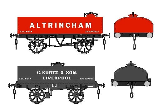
Plain rectangular tanks were more common they were first seen in the 1880s, very few were built after about 1927 but a
couple appeared as late as the mid 1940's.
A problem with
rectangular tanks is that there is a large surface on the liquid inside. When
the liquid sloshes over to one side of the tank a lot of weight moves a long
way and this makes the wagon unstable. One way of reducing this is to build
metal baffles inside the tank, known as 'anti slosh plates' but this added to
the cost of building the tank and the difficulties of maintaining it. As plate
rolling technology improved tank barrels could be made into cylindrical forms
by bolting or riveting a number of curved plates together. Tanks of this type
appeared on the railways around the beginning of the twentieth century.
Assuming the tank is full (rail and road tanks never travel when only part
full) the free surface on top of the liquid is small. When it sloshes from side
to side very little weight is moving and it does not move far from the centre
line so the wagon remains stable.
Cylindrical tanks became mandatory for all Class A liquids in 1902.
In N Gauge the Peco ten foot
wheelbase tank model is typical of the riveted tank designs with the joints in
the plates clearly visible on the tank body. The Minitrix tank, the Peco long
wheel base tank and the W&T tank wagon kit all have a smooth outer casing
with no visible rivets. These represent tanks which have been wrapped in
insulation with a covering sheet of metal. Insulated or 'lagged' tanks are
needed where the liquid needs to be kept cool (milk) or where heating is
required to make the liquid flow (thick oils and bitumen). The insulation used
was usually cork for cold liquids or asbestos fabric for hot cargo. On the
heated tanks there was sometimes a group of steam pipes visible on the end (see
Fig ___ where the APOC tank has these). Bitumen (or tar) sets solid at normal
temperatures but it is not very flammable and the railway bitumen tanks built
after the 1940's often have 'flame tubes' fitted. These tubes entered the tank
low down at the ends and lead up the chimneys on the top. At the discharge
point a gas 'lance' (a metal tube on the end of a flexible hose) was lit and
inserted into the tube to heat the cargo so it would flow.
One point
worth noting is that the lagged tanks sometimes had flat ends. The tank inside
was domed as usual but the cladding was formed into a flat-ended tube often
with a slight rim, similar to that on a steel drum, around the outside edge at
each end. This means we can use a standard length of tube or rod and add a
paper wrapper to form the tank. This in turn means that we can use
photocopiers, computer printers and the like to add the livery to the wrapper
and a number of flat-ended tanks have been included in the drawings.
An
alternative often seen on lagged tanks was to form the end into a shallow cone
shape. The British Railways standard forty five ton bitumen wagons had this
kind of end. These wagons were based on the standard forty five ton long
wheelbase tank as offered by Peco in both ready to run and kit form. Bernard
Taylor of Taylor Plastic Models has released an etched metal kit of the coned
ends and the associated 'flame tubes'. The modification involves cutting away
the ends of the Peco tank body then fitting the replacement coned ends and
other details. I have not attempted this conversion myself and I am told it is
somewhat fiddly but the end result looks appreciably different from the
standard Peco offering and makes a pleasing model.
Making a flat cone
yourself is not easy, the best method is to cut a disc of thin plastic card,
the disk should be about one and a half times the diameter of the tank barrel.
The cone shape is formed by making a slit from the centre to the edge and
sliding one side over the other until the required depth of cone is formed.
This cone is then glued and held with sticky tape to set. When dry the cone can
be offered up to the tank barrel, marked and then cut to size (inking the end
of the barrel is the best option for marking the inside face of the cone). When
gluing the cone in place make sure the overlapping joint is at the bottom,
where it will be much less visible.
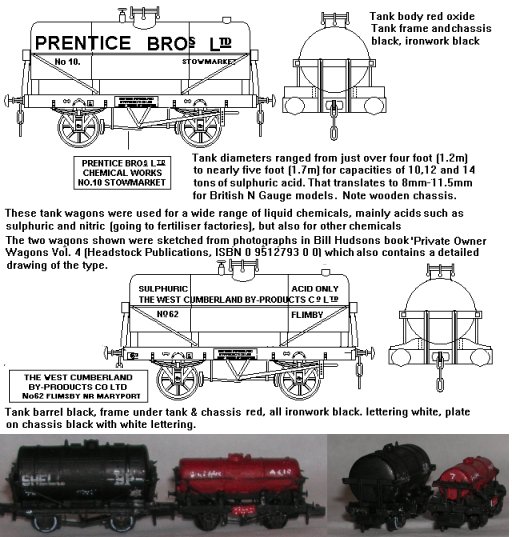
Liquid chemicals shipped in bulk include the products
of the town gas works; ammoniacal liquor, tar and naphtha. Tank wagons were
also used for various alcohols, cleaning fluids and of course acids. Of the
acids sulphuric is the most important but a lot of hydrochloric acid was
produced as a by-product of various processes and a number of tanks were built
for this traffic. Since the 1960's bulk shipments of nitric and ascetic acid
have become more common.
Several of these liquid chemicals 'eat' metal
and, until the technology was developed to coat the inside of tanks with rubber
or glass, wooden tanks were used. Fig ___ shows two variations on this theme,
both dating from the later part of the nineteenth century. The upper drawing
shows a wagon built to carry chloride of iron liquor, the sketch is based on an
illustration in Bill Hudson's book Private Owner Wagons Volume One (see
Bibliography for full details). Iron chloride is made by treating iron with
hydrochloric acid, it was and is used in drawing wire and also in various
chemical processes. Treated and dehydrated it produces finely powdered iron
which is a key catalyst in the synthesis of ammonia (a process developed during
the First World War).
The body of this wagon was made up of wooden
planks lined with tarred felt, a separate tank was built inside from two layers
of planking with an inch or so of tar and sand sandwiched between them. A
simple filling hole was provided on the flat planked roof, covered by a pottery
(fired clay) lid. The Graham Farish salt/lime wagon has sides with only four
planks but it forms the basis of a passable representation of this wagon. The
roof of the Farish wagon can be lifted off but the peaked ends are part of the
body moulding and have to be cut off (keep these with the roof in your 'bits
box' though as they can be useful). Make a new top from 1mm planked plasticard
and fit this to the body. Trim down the end supports on the body so that a
30x30 thou bar can be mounted across the ends later, do not fit the bar in
place at this stage. You need to do this after mounting the roof as, depending
on your source for the 1mm scribed card you might not need to do any trimming
at all.. I used postcard for the top which I scribed before fitting, this meant
I did have to trim the end supports.
For the pottery cover make a small
ball of Milliput something less than 1mm in diameter (do this when making
something else, you need only a tiny amount). If the top of the wagon has
already been painted scrape some paint away where the cover is to go and whilst
the Milliput is still soft press this down in the required position to form a
flat disk with rounded edges. You will probably need to smooth off your finger
print with a fingertip or old modelling knife blade moistened with spittle. The
Milliput should self adhere to the plastic card. I wanted a 'bolt-down' metal
filling dome so I used a length of plastic sprue cut from an Airfix type kit
sprue and sanded this to a more or less cylindrical shape. I made a hole in the
roof sheet and trimmed the sprue to sit on the internal floor and rising 1mm or
so above the wagon top. The bolt-on cap was a disc of plasticard punched out
with a standard leather 'hole punch'. You can add tiny scraps cut from 10 thou
rod for the bolt heads if you wish. If you want a hinged type add a strip of
10x20 thou to one side for the hinge and a length of plastic rod across the top
to represent the locking bar.
This is the point you should paint and
letter the wagon. I used a basic body colour of Humbrol brick red to represent
a faded paint job with rub-down lettering from a sheet of plain white 3mm high
office lettering. I should have laid down a black set of lettering first to get
the shading but I couldn't find any at the time. Around the filler dome I added
some 'track colour' and mat red to represent the rust left by the spillages of
dried out liquor. In the event I made something of a mess of the lettering so I
heavily weathered the wagon and the end result does not look too bad.
The 30x30 thou horizontal end braces can now be fitted and trimmed to
length, these should extend about 0.5mm beyond the sides of the wagon, mine are
about 1mm long and this looks okay. Add small cubes of 30x30 thou strip to the
top of the horizontal bracing bar in line with the end supports and then add
the longitudinal bracing bars on the top. The two rods along the top of the
wagon should sit slightly clear of the planked top, I just glued on two lengths
of 10 thou plastic rod but were I to do it again I would use lengths of guitar
wire sitting on scraps of 10 thou card at either end. Note these line up with
the vertical end post extensions. I suspect these bars might well have been
black in which case I would suggest painting them before fixing them in place.
You can use either fine guitar string or single strands from electrical
wire to make the diagonal bracing as shown in the drawing. Again these may well
have been black so paint the wire as you are fitting it. I used the electrical
wire and looped one end of the wire round the end of the rod, passed the free
end under the wagon, through the brake V hangers, then up to the other rod).
The lower sketch in Fig ___ is taken from a photograph in 'Private
Owner Wagons from the Gloucester Railway Carriage & Wagon Company Ltd'. by
Keith Montague (OPC 1981 - SBN 86093 124 2). It shows a 'slurry' wagon with a
separate tank carried on a solid floored chassis. The wagon chassis and floor
could be made using either a P.D. Marsh 1-plank body on a Peco chassis or a
Peco single bolster wagon kit. In either case sand down the end to floor level
to leave just the side planks. On the Peco wagon carve and sand off all the
body side detail as well. Building the tank itself would require patience,
personally I would start by cutting a block of wood to size and covering this
with scribed cartridge paper to represent the planking. The heavy external
framing would then be fretted from postcard and attached with PVA glue. The end
frames bracing the tank could be knocked up from plastic card (30 thou thick by
1mm high) or a couple of thickness' of postcard glued together. The heavy end
diagonal stanchions are from 30x30 thou strip and the side wires from guitar E
string or strands of electrical wire.
On the positive side the livery
is easy to apply as the boards carrying the firms name on the tank sides can be
made up separately and added to the finished tank. Similarly the side planks on
the wagon itself can be worked up prior to attaching them to the vehicle. As
both involve white lettering on a black background you have the option of
drawing these at a comfortable scale and reducing them on the local Library
photocopier. If you do this use PVA to glue them in place as some other glues
contain solvents which allow photocopies to smear.
Fig ___ Sketch of
wooden bodied chemical tank wagons
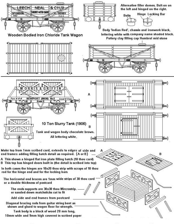
From the photograph of the slurry wagon it is not possible to
see the top of the tank body and the two possible filling hatches shown are a
pure guess. It is possible (though unlikely) that the whole top was lifted off
for access.
Bachman offered a model of a one plank wagon with a red body marked Morris and Griffin Newpoer (Mon) No.1 which they described as 'a wagon to carry a rectangular slurry tank', but the model may have been produced from the wagon makers photo of the slurry wagon shown in the drawing, the tank being added later by Morris and Griffin themselves or another firm.
The slurry tank in Fig
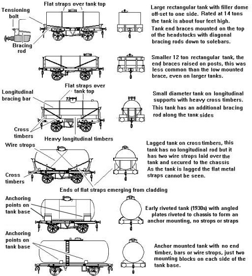
___ sits on a fully planked wagon floor, this was very rare for tank wagons. Rectangular and D shaped tanks sat on an open chassis frame, securing the beams at either end and sometimes straps over the top or actually bolted down using additional mounting plates. For cylindrical tanks there were two basic approaches taken, both involving a timber supporting frame cut to suit the tank body shape
bolted to the wagon chassis. The 'saddle' mounting which had four (ocasionally six) transverse beams cut to the curve of the tank bottom and the 'cradle' which had two longitudinal wooden beams, again cut to fit the base of the tank. The cradle type was better suited to wooden underframes and was largely replaced by the saddle type as iron and steel underframe came to dominate.
To hold the tank down in the frame there would be
either wire rope strops passed over the top or flat metal straps (sometimes both).
The wire rope strops were not used on new builds from the mid 1920s, on cylindrical tanks these rope strops were usually crossed to either side of the
dank filling dome. On wagons built after the mid 1920s, without the wire strops, a longitudinal bar was added bewtween the end frames. The straps or strops were secured to the chassis with some
form of tensioning adjustment. At either end of the tank there would be quite
solid supports to stop the tank shifting along the wagon in transit or when
being shunted. These usually consisted of a pair of vertical posts with a hefty
cross piece at the top. The cross pieces had holes in the ends through which
metal rods were passed, leading down to somewhere about the middle of the
chassis where they were bolted in place. The ends of the rods were threaded
where they passed through the end timbers and nuts were then tightened onto
these to hold the assembly in place. The metal rod running along the side of the tank between the two end timbers (introduced in the mid 1920s) also had
tensioning bolts on the ends.
In the case of rectangular tanks the end
supports might be set on top of the buffer beam, raised slightly to lie along
the lower portion of the tank itself, or (less common I believe) supported high
enough to lie along the top edge of the tank. On rectangular tanks where the
end timber was mounted low down it was usual to only fit the diagonal metal
rods, missing out the horizontal rod. Where the end timbers were mounted
directly onto the chassis, only done with fairly low tank bodies, the diagonal
bars were sometimes omitted as well. Square tanks came in a range of sizes,
some had quite low tanks as seen on the Graham Farish model whilst others were
perhaps twice as high.
On both square and
cylindrical lagged tanks the flat metal holding down straps across the top of the tank did
not always show as they were laid round the tank itself under the cladding
sheet. The lower ends of the straps were visible where they emerged along the
lower sides and extended down to the solebars. These straps were laid on the
outside of some lagged tanks, early six wheeled milk tanks are one example
where the straps were external and visible.
Things changed about the
time of the Second World War with the widespread introduction of the 'anchor
mounted tank'. This did away with the straps, rods and end timbers, instead the
tank body itself was fitted with integral supports which could be bolted to the
chassis. This was not exactly ground breaking, the riveted iron Kurtz chemical
tank shown above was secured to the wagon with integral fixings, and there were a few rather ordinary looking tanks mounted to the chassis with heavy riveted plates at each end, but it was
only when welded tanks became reliable that anchor mounting became standard.
Fig ___ Tank wagons showing tank securing methods
Note that not all railway tank wagons had ladders on the
sides for access to the top and on some the ladder was on one side only.
British Railways built a number of tanks using the traditional end bracing and diagonal rods on the standard
RCH twelve foot wheelbase chassis in the 1950's and from a modelling point of
view several of these tanks make an interesting proposition. The W&T tank wagon kit, designed to fit the Peco 10 foot wheelbase chassis, can be used to model these. The chassis can be a cut down Peco fifteen foot wheelbase type and if you ask when ordering W&T will supply a length of suitable tube you can cut down to length to suit your model. This is more fully discussed in the section on Kit
Bashing.
Another early tank on the twelve foot wheelbase chassis was
used by ICI for train-ferry traffic in chemicals to the continent. This was a
little different in design. The tank itself was smaller (possibly due to the
weight of the cargo it carried) and it was secured with straps over the body to
allow the tank barrel to be changed. For this you can use the Ratio Oil Tank
kit, mounted upside down and with a new filling dome from the head of a pin,
walkways from card as above and laddering from etched brass signal ladder.
Up to the early 1970's chemical tank wagons used plain mild
steel tank barrels and were confined to a single traffic. By the early 1980's
there was an increasing shift toward using stainless steel (or 'staybright') tanks which can be
washed out and used for a different cargo.
The typical diameter for a
cylindrical tank would be about six and a half feet, roughly two metres, but
much smaller tanks were also built. Most tanks for carrying chemicals seem to
have used tanks of about five foot or one and a half metres in diameter (some were as small as four feet in diameter), the largest size of Plastruct tube in the Fineline range is about right. My model is based on the Peco 9 foot wheelbase chassis with a tank from Plastruct Fineline tube, the ends are 30 thou card trimmed and sanded after attaching to the tube. The photo shows the difference in size between these acid tanks and a standard tank wagon. Note the sketches and the model shows longitudinal timbers supporting the tank, the pictures and drawing in Mr Hudsons book do not show these (although I believe some tanks did have them) The corrected model is described in the section on Kit Bashing.
Fig ___ Tanks for carrying acids
Not all tank wagons had a single tank, there were a few which had two
tanks, either long cylindrical tanks mounted side by side on the wagon or two
short tanks of normal diameter. W&T offer a neat kit in N gauge of the type
with two long tanks side by side, this fits on a standard Peco 10' wheelbase chassis and has
separate loading hatches, enabling a bit of variety in the model. These were
mainly used for goods such as edible oil, where consignments tended to be small
and the facility for loading two grades was useful, although some petroleum oil
company tanks used this arrangement. I made one of the W&T kits up, without the filling hatches and with some simple 'pipeworks' added to one end, as a GWR gas tank wagon. These were used for supplying coaches and outlying depots with compressed coal gas. The same kit can be used for an LMS type by trimming off the coupling plugs, mounting it on a 12' wheelbase chassis and adding a plasticard platform at one end with handrails across both ends.
Fig ___ W&T Twin tank wagon made up as a gas tanker
wagons 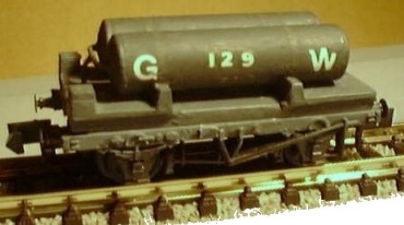
There is a well known 'OO' scale
kit of a twin tank wagon with the two short full size tanks, the prototype was
built by Cravens in 1927 for the Anglo Persian Oil Corporation (APOC later became BP,
and BP itself has purchased a few divided tanks for oil products). The APOC
tank was registered on the GWR and is listed as being for 'fuel oil' but that is a wide ranging term, there
are six basic types, ranging from the lightest (number one fuel oil) used for
domestic heating systems, through diesel oil (number two), to heavier grades
used in industrial heating systems and the so called 'residual fuel oils' or
'heavy fuel oils' (HFO, numbers five and six) which are almost solid and have
to be heated to flow at all. The APOC tank had heating pipes so it could carry
one of the heavier crude oils which contain a lot of wax and set solid at
normal temperatures. At some point at least one of these tanks passed to a company called Lubricating Products, with whom I believe it continued in use into the 1970s, it still existed in the 1980s but by that time was in a very dilapidated condition (possibly retained for internal use only).
Finally there were tank
wagons having a single tank body with an internal partition (sometimes two
partitions) and separate loading hatches for each section. These allowed two
(or three) different grades of liquid to be carried. In the drawing I have
included two such wagons sketched from photographs in Peter Matthews book on
Private Owner Wagons (see Bibliography). The British Petroleum wagon dates from
the 1920's and was probably used for lubricating oils as these would be more
likely to be shipped in small segregated consignments than fuel oils or petrol.
Fig ___ Segregated compartment tank
wagons 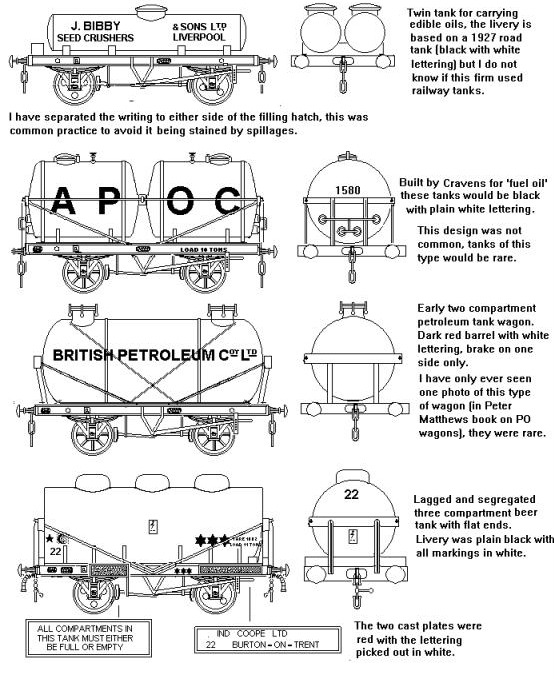
The three compartment beer tank and the twin tank APOC wagon are easily made using the peco tank wagon kit, see the section on Kit Bashing for details. The APOC logo had disappeared by the end of
the 1920's so the livery shown would serve on a late pre-grouping layout or one
set in the earlier years of the Big Four.
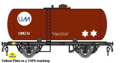
Esso were the first oil company to move towards larger four
wheeled tanks, a fifteen foot wheelbase thirty-five ton capacity anchor mounted
tank was introduced in 1957 and similar tanks were subsequently used by other
companies carrying a range of liquids.
The 'Esso' tank came in two
varieties, class A tanks had a body just over twenty five foot long, the Class
B tank was twenty two and a half foot long, both were about seven foot in
diameter. These tanks had no 'skirt' at the base, they were supported on four
metal brackets, each about a foot wide, mounted two to a side. Bernard Taylor
(of Taylor Plastic Models) described the modelling of this tank wagon in an
article in Practical Model Railways, he used Plastruct plastic tubing &
domes (TB-18 with VHE18 domes) on a Peco fifteen foot wheelbase chassis kit.
The side frames were made from card, but you have to sand down the Peco
coupling retainer as this will show under the tank ends.
The later 35
ton and 40 ton designs all had the skirt as on the Peco 45 tonner, but being of
smaller capacity they had a smaller tank (Plastruct TB-20 with VHE-20 domes is
about right). These are more difficult to model as you have to sand the tube
flat at the bottom and make up the skirts from 10 thou card
These tanks
were also used by United Molasses, I understand they painted the tank red with
their logo in blue on a white circle. There may well have been a white six
pointed star or possibly two in the lower right of the tank and there would
probably have been a number to the lower left of the tank. The yellow Cc patch
(Commuted charge, an accounting method for PO vehicles) is discussed under
Liveries PO Stock.
Fig ___ Early 35 ton anchor mounted tank
wagon
The Peco 45 ton oil tank wagon, dating from 1963, is an anchor mounted type although this tank had a very large tank, the base of which dipped below the solebars, and has a 'skirt' around
the base of the tank whereas early anchor mountings were visible on the lower
sides of the tank body as shown above. The larger barrel on the 45 ton tanks was too wide
to allow the fitting of side ladders (they would have exceeded the loading
gauge), so access to the walk way is at one end of the tank producing a rather
distinctive appearance.
Lagged and steam heated wagons were used for
bitumen and other heavy oils. Bitumen
from Californian crude oils or recovered from the tar sands of Trinidad is
shipped as a solid in tank wagons and must be heated to allow discharge. Most did not use the loco steam supply in transit
but had to be heated on arrival as the tar would have solidified. The APOC twin tank wagon shown above has the fittings for the steam heating supply, the arrangement seems to have been fairly standard up to the second world war. After the second world war a new system called 'flame tubes' was introduced, these were simply tubes run through the tank from the lower part of the end to a 'chimney' on the top at the other end. I understand propane gas torches were used to heat the bitumen to melting point, when the valves could be opened and the cargo emptied from the tank. As everything
they carried was not very flammable they were allowed to use bottom discharge,
often the valve handle was mounted on the top next to the filling dome.
Fig ___ Tank wagons used for carrying Bitumen
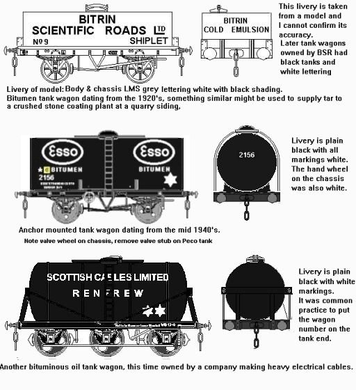
The tank at the top is a typical square bodied tank, note the
off-set filler dome. The prototype was rather higher than the Graham Farish
tank and note the method of securing the tank with heavy wooden beams on the
ends held in place with angle section steel plates and two T section end
braces. The solebars were wooden so the W&T white metal 'tar tanker' kit on a Peco 10' wheelbase wooden chassis would serve well for this tank. I had always thought that the majority of the rectangular tanks were black, I am told however that the most common colour was red oxide, followed by grey with black as the third most popular option.
The sketch in the middle
is of an Esso 'anchor mounted' tank from a picture in Peter Matthews' book on
PO wagons, the design dates from about 1944, the oval Esso logo appeared in
1938 or 1939. The tank body is as long as the chassis, the ends are virtually
flat and there is a rim round the edges similar to that on top of an oil drum.
This tank, with its basic black and white livery, could be made up by drawing
the livery out in white on black (do it in outline and fill it in if you do not
have access to a computer) then using a photocopier to produce a double-sided
wrapper to about the correct scale. The tank barrel would be any bit of tube
about the right size fitted to a ten foot wheelbase Peco chassis with Romford
or Mike Bryant spoked wheels. The ladder would be signal ladder and the grating
on the top could be a piece of 10 thou plastic card with a scrap cut from a
pair of fine nylon tights glued on before cutting to size. Alternatively you
might invest in some small wire mesh screen material used for oil filters and
the like, try back street hardware shops for this. This material is also
available in small discs in 'hippy' type shops where they are sold as
'screens'. Unfortunately these are only available in sizes up to about one inch
in diameter.
The lower tank is carried on a six wheeled chassis similar
to the familiar milk tank wagons, the extra wheels allowing a larger capacity
tank to be used. This sketch is from a photograph dating from the early 1960's
but similar wagons had been in use from the mid to late 1930's.
British Railways used a cone-ended tank
similar to the Peco long wheelbase Class B tank and as mentioned above there is
a conversion kit for the Peco tank available from Taylor Plastic Models which has the post war flame tubes.
Bitumen tanks were amongst the last tank wagons to travel singly through the
system, making them an attractive proposition on a model railway.
Bogie Tank Wagons
Bogie tankers are not so new as people
think, although they were not originally popular with the oil companies as they
had problems with the sharp curves in the refineries. The first is believed to have been a 20' example, on somewhat unusual bogies, registered on the Caledonian Rly in 1900. The drawing below is
based on an illustration in R Tourret's book on petroleum tank wagons (see Bibliography), this
was a one-off wagon built in 1929 but a similar design (with wire strops over the tank) was built in 1908. The drawing is not a copy of the original,
instead it shows how something essentially similar can be made using two Peco
four wheeled tank kits and Graham Farish goods bogies. No trussing is shown under the chassis, the ptototype started out with trusses but these were removed very soon after it entered service, saving the modeller a tricky job.
Fig ___
Vintage bogie petrol tanker
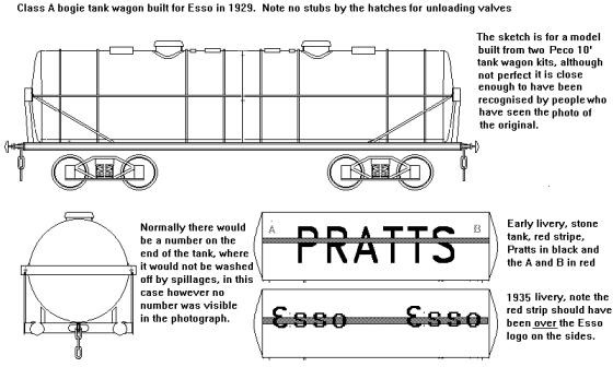
My own model was made some 20 years ago, the layout it was built for had no use for a Class A tank and I didn't fancy my
chances of painting the red stripe round the body so mine is a 'Class B' tank,
if asked its carrying fuel oil (hence the plain black tank and the valve
spindles still in position on the top of the tank). I used some PO wagon side
transfers to letter the wagon with the small A and B at each end from a sheet
of commercial rub-down lettering. The chassis is
a sandwich of card and strip with buffers culled from a redundant Lima
wagon chassis and Graham Farish diamond frame bogies (fitted with Mike Bryant
wheel sets) held in place by small wood screws. The model was made the week
after the new Peco tank models appeared in my local model shop, the photo was
taken some years later and as can be seen the chassis has warped slightly. I
used Microweld to make the model, but I probably used too much, causing the
warping. Building this model is described in the section on Kit Bashing under Modelling unusual tank wagons.
This was not the only design of bogie tank wagons, there were a few variants for oil and a chemical firm called Murgatroyds had a small number (although using four different designs) of rather short bogie tanks for chlorine. Some surprisingly vintage tanks lasted into the early 1960s, including some anchor mounted tanks built for the Oakbank Oil Co (a Scottish firm dealing in shale oil products), several of this comapnies tanks survived the take over by APOC in 1919 and carried Oakbank livery at least into the 1940s. The Oakbank tanks are illustrated in in R Tourret's book on petroleum tank wagons (see Bibliography) with a drawing under the entry for BP and a phot associated with the entry for Oakbank.
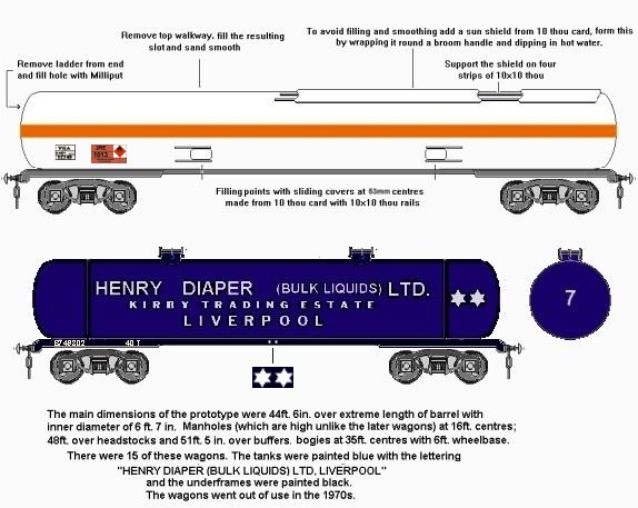
The Scammel articulated road tanker lorry of 1927
introduced the 'frameless' tank, this tank was self supporting in the centre
with the load supported on sub-frames at either end. By the 1940's railway tank
wagons were being built using a frameless design although they remained
uncommon until the later 1960's (when the 100 ton bogie oil tank wagons were
introduced in large numbers). The example shown below in Henry Diaper livery is a 40 ton variant dating from 1949 that remained in use into the 1970s.
In 1966 the prototype for a 90 ton frameless bogie tank appeared, in Shell BP Class A livery. This proved a success and the trials coincided with an increase in permitted axle loading to allow 100 ton GLW bogie tankers, by 1968 several firms were operating fleets of 100 ton bogie tanks including wagon hire firms such as BRT (who rented them out to oil companies, adding the oil company logo to the right hand end of the tank). The prototype bogie gas tanker was built in 1967 for Esso, by which time the livery was a white tank with the horizontal orange band, I believe BP subsequently also operated gas tanks of this type.
Fig ___ Early frameless tank wagon and
details on converting a Graham Farish 100T tank to a gas carrying tank.
One advantage of the frameless bogie tank
wagon is that the tank itself can be made larger in the centre, sagging
downwards so as not to foul the loading gauge, these tanks are called 'oblate'
tanks. There is a limit to how long a tank wagon can be, so as not to foul
stock on adjacent tracks on curves, and of course the height and width of the
tank are similarly constrained, so the oblate tanks are useful when carrying
lighter liquids. As an example the standard bogie Liquid Petroleum Gas tanker
on British Railways has a gross loaded weight of ninety tons, the same basic
design when carrying oil has a GLW of 100 tons. By the early 1980's companies
such as Procor had introduced frameless oblate tanks TOPS coded TEA these have
a gross loaded weight of 102 tons and are able to carry close to 80 tons of
cargo. Oblate tanks cost more to build so the standard cylindrical tanks remain
the most common in service.
Tanks for Compressed Gasses
The railways made use of coal gas shipped in a range of tank wagons, often on retired
four wheeled coach chassis, I believe it travelled in ordinary goods trains
to where it was required. It was then parked in a siding and used to recharge
the gas cylinders on coaches, used for both lighting and (in kitchen coaches)
cooking. The wagons used mainly had multiple tanks about three or four feet in diameter but the LMS (and possibly others) built some larger tanks with a single tank on a long wheelbase chassis.
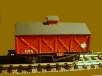
Some PO tanks were in use for chlorine by the later 1930s which were of a curious 'hutched' design. The tank itself was mounted inside
what appeared to be a fairly standard planked wagon body, typically about seven
or eight planks high with a peaked roof similar to those on salt and lime
wagons. On top of the roof, usually in the centre, was a small ventilated box
housing the filling cap or 'dome'. These hutched tanks were used for dangerous
cargo such as chlorine. Both ICI (Runcorn) and Castner Kellner Alkali (Runcorn)
operated similar tanks for the carriage of liquid chlorine in the 1930's. I am
not sure when they were phased out but I believe some were built with a ten foot wheelbase, suggesting
they were in use in the 1950's. Modelling this wagon is discussed fully in the
section on Kit Bashing.
Fig___ Model of a hutched tank
wagon
. LPG (Liquid Petroleum
Gas; Butane & Propane principally) has been moved in bulk by rail since the
1950's, British Railways actually built a small fleet of twelve foot wheelbase
20 ton compressed gas tanks to dia 1/306 in 1952 for propane and butane traffic from Fawley refinery. These were
classed as Class A tanks and from 1905 the rules required these to be both loaded and discharged via the top (following a fire caused by a leaking bottom valve) so they had a filling dome on the top with ladders to either side (bottom discharge of class A liquids was allowed from the later 1960s).
The tank was lagged, twenty one feet long by seven feet in diameter and carried
on a wooden frame with traditional braced end frames. These were leased to a tank rental company but I do not know who and I have not been able to confirm the livery.
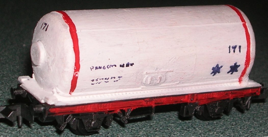
In 1962 Shell BP introduced the first big vacuum braked LPG tanks, similar in outline to the Peco tank (which is currently available only in 1970s Mobil livery), these were later used by other firms (the only change being the removal of the Shell and BP logos from the tank sides.
Fig___ Shell BP LPG tank wagon
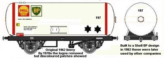
The Peco tank can be back-dated to the original 1962 Shell BP design by adding the side loading hatches, a small manhole on the end and a couple of pressure relief valves on top at one end. The basic livery was originally as shown below, by the later 1960s the shell and BP logos had been removed and these tanks were in use by other firms. The model shown below is for a layout set in the later 1960s and hence does not require the logos on the tank sides.
The prototype bogie gas tanker was built in 1967 for Esso, I believe BP also operated gas tanks of this type. The sketch above shows a typical British gas tanker, there were also some French built ferry equipped bogie gas wagons with a curious rectanglular sheet metal 'chassis', extending to the full width of the bogies and about a foot deep, introduced in (I think) the later 1960s.
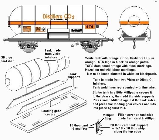
The air braked carbon dioxide tank wagons in
service in the 1990's have an unusual shape, domed at one end but cone shaped
at the other. To model this tank you will need a Graham Farish air-braked wagon
chassis a length of Plastruct TB-18 tube with a VHE-18 dome and you then need
to make the coned end as described earlier. If you can live with the inaccuracy
of having two domed ends (from photographs I believe this was the original
design for these wagons) and incorrect suspension you can build a 'freelance'
carbon dioxide wagon using the ends from a couple of Vicks inhaler tubes on a
Peco fifteen foot wheelbase chassis. The domed end(s) on either of these tanks
have a round man-hole on the end which can be represented with a 2mm disc of 30
thou card punched with a leather punch.
Fig ___ Carbon Dioxide Tank
Wagon
See also the section on Livery - Tank Wagons for an earlier examples
of tanks for compressed gasses
De-Mountable tank wagons
Tanks which could be
lifted off the wagon and transported by road, so called 'de-mountable tanks',
appeared in the later 1930's but only really found favour after the Second
World War. In the 1950's and 1960's the oil companies used de-mountable tanks
for carrying ethyl-lead, which was added to petrol as an 'anti-knocking' agent.
Beer and various chemicals such as acids, glues and resins have also been moved
in de-mountable tanks. Sketches of various demountable tanks will be found in
the section on Kit Bashing. A sketch of a demountable sulphuric acid
tank will be found in the section on Freight Operations - Explosives, Chemicals
& Gasses. Modelling demountable tank wagons of various kinds is discussed
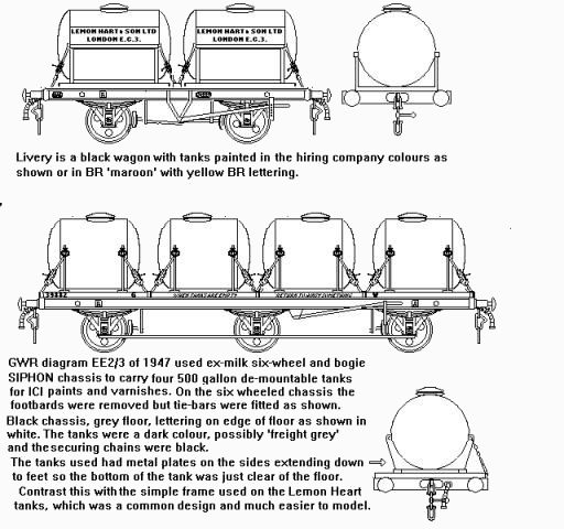
in the section on Kit Bashing. The sketch below shows a typical twin
de-mountable tank wagon being used to carry liquids for the Lemon Hart rum
company and a larger vehicle (one of twelve built by the GWR) carrying four
tanks for varnish.
Fig ___ De-mountable tanks wagons
^
Go to top of page
International Good Guys ~ Making the world a
better place since 1971 ~ Site maintained by

All material Copyright © Mike
Smith 2003 unless otherwise credited