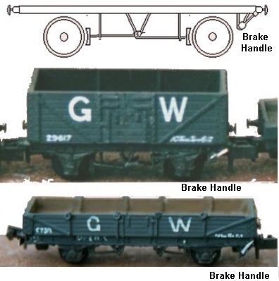
Fig ___ Early hand brake designs
Brakes
Very early wagons had no brakes at all, the usual method of parking them
was to put a block of wood in between the wagon spokes. It soon became apparent
that some form of hand operated brake for parking vehicles was a good idea and
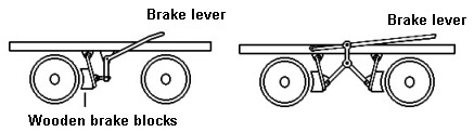
people experimented with various designs. The principle of the most popular
early design is illustrated below. This involved a hinged metal plate attached
to the bottom of the solebar with a wooden brake block bolted to it that
pressed onto the tread of the wheel. Brakes which function in this way are
called 'tread brakes'. In the example shown on the left this was operated by a
simple lever and acted on only a single wheel. Privately owned wagons with this
kind of brake were still seen as late as the early 1930's on running lines, and
probably survived until the Second World War or shortly after on privately
owned lines in larger factories, collieries etc. Railway company owned examples
remained in service into the early BR era. With the short wheel base (typically
five foot or one point six metres) of the very early mineral wagons it was
possible to arrange for these simple hinged brakes to apply to two wheels as
shown on the right.
Fig ___ Early hand
brake designs
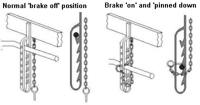
To 'park' a wagon the lever had to be tied down which
was not terribly efficient. By the late 1830's some wagons were fitted with a
loop of metal passing round the brake lever, close to the handle, and fitted
with a toothed ratchet on the inside. The lever could be pushed down and hooked
into the ratchet to secure the brakes but a sudden shock would often cause the
lever to disengage. To avoid this problem the loop was drilled with a series of
holes and a metal pin was attached (secured with a short length of chain). When
the pin was passed through the holes it would lock the brakes on securely. This
simple device has remained the most popular method of locking the brakes on
goods wagons ever since.
Fig ___ Brake
ratchet and 'pinning down the brakes'
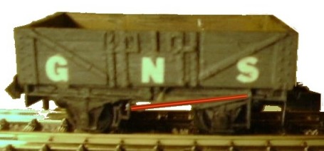
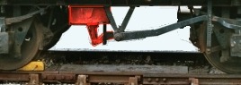
This simple type of brake, with the hinged plate and
very long brake handle, remained in use for many years. Examples were seen into
the early BR era. They are usually referred to as 'long lever brakes'. In the
photo below the brake handle has been tinted red to let it show up more. The
wagon is based on a standard Peco chassis with the V hanger, right hand brake
shoe and brake handle trimmed away. A new brake handle was added using 10x20
thou strip between the pin-rack and a small block of plastic glued to the
underside of the chassis.
Fig ___ Wagon
with 'long lever' brake.
In the 1880's a new design appeared
called the Morton brake. The long brake handle extended upwards from a
centrally mounted V shaped bracket (called a 'V hanger'). The brake blocks were
pressed against the wheels by push-rods which passed through metal supporting
loops called 'brake hangers'. The long brake handle allowed the shunter to
exert a considerable force on the brakes. The handle generally extended up
towards the right hand end of the body an arrangement called a 'right handed'
brake, but some handles extended up toward the left hand end (left handed
brakes). The handle on the end of the brake lever was usually painted white to
make it more visible.
Peco, Graham Farish
or Minitrix ten foot wheelbase wagons all have the Morton pattern brake. The
brake levers are the same on both sides of the wagon, extending to the right.
The Morton brake was a popular design which became part of the Railway Clearing
House (RCH) standard specification for private owner rolling stock of 1923.
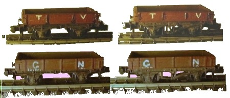
Fig___ Morton pattern brake gear &
variants
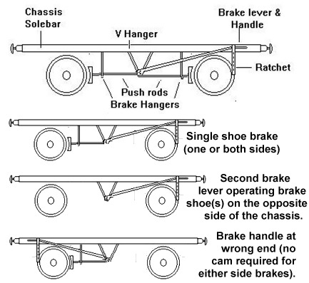
To save money the hand brake was often only fitted on
one side of the wagon, the other side having wheels with no brakes at all. This
was done with both the 'long lever' and 'Morton' pattern brakes. During
shunting the goods shunter often had to run alongside the wagon to apply the
brakes but having brake handles on only one side of the wagon meant he often
had to run across the track to get to the other side. Accidents in these yards
often involved the loss of a limb and larger railway companies had special
departments making prosthetic limbs for victims. Regulations and bye-laws were
enacted to get the various users of goods rolling stock to turn wagons so that
the brakes were all on the same side but this was seldom totally effective on a
railway system with many wagon turn tables.
Fig___ Wagons with brakes on one side only
In older wagons, even with brake handles on both sides, the brake might only
operate on one wheel. By the turn of the century railway company policy was to
have a brake handle on each side of the wagon which applied a brake to both
wheels on that side. This policy only applied to new wagons however, older
stock with a brake handle on only one side remained in service into the early
twentieth century.
On most wagons the brake
handle only operated the brakes on the same side of the wagon, resulting in two
so called 'independent' brakes, one on each side. By adding a connecting rod
between the V hangers underneath the wagon the handle on one side could operate
the brakes on all four wheels. The brake handles were then fitted with a cam
arrangement on the V hanger end so that when one handle was operated the other
did not need to move. This arrangement could only be fitted on wagons without
hopper or bottom doors. An alternative design, intended to avoid payments to
the holders of the patent on the Morton brake, had a cross link between the V
hangers but with both handles at the same end of the wagon, right handed on one
side, left handed on the other.
One money
saving dodge was to have brake handles on both sides with a connecting rod
between the brake V hangers but with only one wheel being braked on one side.
The GWR modified several of their Iron Mink goods vans in this way in the later
1920's and this can be easily modelled by simply removing the unwanted parts of
the brake gear from a standard Peco chassis.
In some cases wagons were built asymmetric brake gear, with the V
hanger off-set toward one end of the wagon. This was mainly associated with
wagons using a non RCH standard chassis (usually longer than normal) but
retaining a large proportion of RCH standard brake parts. One arrangement, used
by the Lancashire & Yorkshire Railway on their 12 foot wheelbase chassis,
had two V hangers on one side but only one (mounted toward the right hand end)
on the other. The opposing V hangers were connected together under the chassis.
The same basic chassis was used both with and without vacuum brakes for a range
of L & Y vehicles.
Fig___ L&Y
end-door only 20 ton mineral wagon with asymmetric brake gear
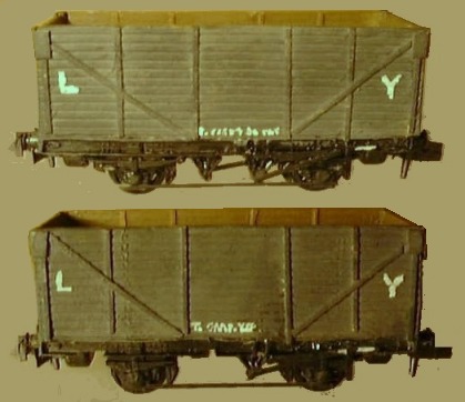
It is perhaps worth noting that the
wagons shown were built to carry coal for ships at about the turn of the last
century but were transferred to general freight duties in the 1920's.
In about 1911 the RCH ruled that any stock
built after that date had to have 'either side, right handed' hand brakes
fitted by 1938. This means having a brake handle on each side of the wagon,
each extending up toward the right hand end of the vehicle. The rule allowed
for independent brakes on each side of the wagon (necessary for hoppers or
wagons with bottom doors). Any stock not fitted with either side right handed
brakes by 1938 was to be withdrawn from service. The railway companies were
already building to this standard but a lot of private owner stock was still
being built with brakes only one side and some older railway company wagons
were still in service with this arrangement. Also some wagons had the brake
lever extending toward the left end of the body. In the event, due to the
financial troubles of the 1930's and the following war, some non-standard
wagons survived the Second World War and a few made it as far as the 1950's.
Longer wheel base stock equipped with
Morton type brakes sometimes had a long brake handle extending up from a
central brake hanger but some used a standard length brake handle. The handle
did not therefore extend all the way to the left hand end of the vehicle, but
following standard practice it did always extend to the right of the V hanger.
The Morton brake was the most popular
system for 'either side brakes' but it was not universal. The GWR for example
built wagons which had a very short lever which could be mounted either on the
left or right hand end of the chassis. This was the Thomas Brake, which was
developed into the Dean Churchward brake (usually abbreviated to DC). Wagons
equipped with DC brakes were in use into the 1950's at least. The DC brake used
a 'worm drive'; the handle was attached to a rod with a screw thread and as
this was turned the thread engaged with a toothed rack which applied the
brakes. One big advantage of this design was that the brakes did not need to be
'pinned down' as the worm drive provides such high gearing. The worm drive is
used on most model railway locomotives, the 'worm' is attached to the motor
shaft driving a toothed gear wheel which turns the axle, you can make the
wheels go round easily by turning the worm with your finger, but you cannot
turn the wheels to make the motor spin. There were sometimes two V hangers on
each side of wagons fitted with DC brakes, especially if it was longer than 10
foot wheel base, and the short handle was again painted white.
Fig ___ Thomas and DC Brakes
The shorter model wagon shown above has had its brakes
modified to represent the Thomas type. On some of these wagons both brake
handles were at one end of the wagon, so on one side of the wagon the brake
handle is at the 'wrong end'. To model this brake type the brake handle and pin
rack was removed from the right hand end of the Peco chassis, a small scrap of
plastic was added under the chassis to represent the triangular support and a
scrap of 10x20 thou strip was glued to this to represent the handle. The longer
wagons, a GWR Open C, has the DC brake, with the double V hangers associated
with a longer chassis.
Modelling the GWR
high sided open was described in Railway Modeller May 2001 (Traffic for
Tickling Article 3), modelling the GW Open C was described in Railway Modeller
Jan 2003 (Traffic for Tickling Article 13)
One final variant seen on four wheeled stock was the end
mounted brake handle. Both the pre-grouping Furness Railway and later the LNER
built some four wheeled iron ore hoppers with the brake handle mounted across
the end of the vehicle, the handle was operated at the right hand end on each
side.
Fig___ Model of LNER hopper (in BR
livery) showing brake handle
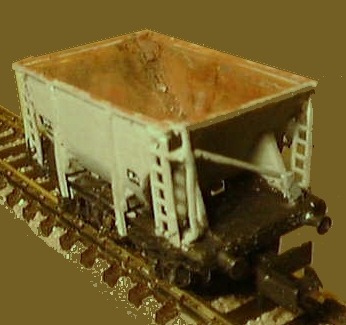
The model
is based on a Farish ore hopper, the end supports should be closer together but
the model was based on a single photograph and I only realised this much later.
BR scrapped older wagons as a matter of policy and after about 1954 most of the
non standard brakes on smaller wagons had disappeared.
Brakes on Bogie Stock
Bogie stock presents additional difficulties for brake
designers. One option is to fit a separate brake system to each bogie with
operating levers or wheels mounted on the bogie sides, the LMS diamond frame bogie had this kind of brake lever. Some designs put the
operating lever or wheel on the front of the bogie, so the shunter had to get
onto the tracks to apply the brake. Older bogie well wagons and the like in
British Railways service often still had their awkward front mounted brake
handles or wheels into the 1970's and possibly later.
The alternative is to
mount the brake gear on the body of the vehicle and carry the action through to
the bogies with linkages. Bogies wagons with this type of brake sometimes had a
V hanger and lever mechanism (with the lever extending up toward the right hand
end of the body). The Graham Farish 'sulphate wagon' has two brake levers on
each side, on the prototype each lever acted on only one bogie. The
handle of the lever operated brake or the hand wheel of the wheel operated brake is usually painted white. The GWR
fitted their DC brake to some bogie stock, the handle being mounted on the
under side of the chassis, usually somewhere about the middle.
Brake shoes
and 'clasp' brakes
On early wagons the
brake shoes themselves were shaped blocks of wood. Wooden brake shoes were used
up into the 1930's on gunpowder vans, presumably to avoid the danger of sparks
causing a fire. Cast iron brake blocks were in use by the 1880's and became the
norm by the turn of the century. In most early brake designs the brake blocks
only pressed on the inner side of each wheel. Later designs had two blocks per
wheel, one pressing on the inside the other on the outer side of the wheel.
These were called 'clasp brakes' and they are mainly associated with power
operated vacuum and air-braked stock (discussed below). Do note however that
not all vacuum braked wagons had clasp brakes. In the pre-grouping era I believe only the LNER used clasp type brakes
in their standard design for vacuum braked goods stock although clasp brakes
were the norm for passenger stock on all railways. Having said which I have
seen one photo of a GWR registered milk tank wagon in the mid 1930's which had
the Dean Churchward hand brake lever and clasp type brakes so perhaps there was
a requirement for clasp brakes on passenger rated stock (if so I am not aware
of it). One feature of clasp brakes is the lack of push rods between the
central V hanger and the inner brake shoes on the standard four wheeled wagon
chassis. This is because clasp brakes are operated by a mechanism fitted under
the chassis between the wheels. Parkwood Models suggest simply removing the
push rods from a Peco chassis to represent a clasp brakes chassis. This looks
acceptable and to date I have had little success trying to add the outer brake
shoes due to the depth of the flange on N gauge wheels. It should be noted that
although BR adopted the LNER vacuum brake, which had clasp type shoes and no
push rods, the standard four-shoe Morton pattern brake was also used for vacuum
braked stock, usually this required a tie-bar fitted between the bottom of the axle boxes on each side. Do not go round removing the push rods on your stock unless you
are sure the type you have modelled had the clasp type brakes.
Braking a train
An
early goods train would have brakes on the loco tender which could be operated
by the crew and passenger coaches carried a guard (the term 'guard' came from
stage coaches) who could operate brakes on the carriage. Goods rolling stock
however would only have a hand brake, which could not be operated whilst the
train was moving. This made stopping the train rather tricky and after about
1850 goods trains had a separate 'Break Van' (this spelling was used up to
about 1870). This was a wagon fitted with weights (typically ten tons) and a
set of brakes acting on all four, sometimes six, wheels. There was usually a
small 'hut' type structure provided for the guard (see also Brake Vans &
Tenders below for further details on these vehicles). The rules required the
guards van to be attached to the rear so there were railway personnel at each
end of the train to warn other trains if there was a problem. With a heavy load
an additional brake van might be marshalled toward the front of the rake as
well although this would be another guard's wages to pay for. The train crew
used the whistle to pass instructions to the brake van crews or guards.
Handling a train with no brakes on the wagons was a somewhat fraught exercise, when setting off the locomotive had to proceed slowly (about walking speed) until all the couplings had tightened, then apply full power to accelerate the train (although 20mph would be a typical speed for such a train). If the train went down a gradient the wagons would tend to 'catch up' with the locomotive, as the line leveled out there was a risk that the slack in the couplings would allow the wagons at the rear to slow down, then as the couplings were pulled tight the effect would ripple down the train until either a coupling broke under the sudden shock load, or the guard would get knocked off his feet in the brake van. This sudden tightening of the couplings is called 'snatching' and was a common cause of broken couplings. To avoid this it was standard practice to stop the train at the head of the gradient and for the guard to walk along the rake applying the hand brakes on the wagons, a practice called 'pinning down the brakes'. Once the brakes were set the guard would wave a green flag and the locomotive would drag the rake onto the incline. Naturally once the train reached the bottom of the incline it was necessary to stop so the guard could walk along the rake and release the brakes, a rather time consuming exercise. For more on the operational problems associated with and-brake only wagons see the section on Freight Operations - Categories of Goods Train and usage of rolling stock.
In America the clearances on the lines
allowed a crew man to walk along the top of the goods vans and open stock so
brakes were fitted with top mounted hand wheels. This meant the brakes could be
applied whilst the train was moving but of course this took time. As the hand
brakes on the British wagons could not be operated on the move when a train
reached a downward incline the train would stop so the guard could walk along
beside the wagons and 'pin down' the brakes to prevent the wagons pushing the
loco down hill too fast. Pinning down the brakes took a fair bit of time and a
train of wagons with only hand brakes had to travel slowly so the brakes on the
loco and guard's van(s) could control it. Because of this various forms of
wagon brakes were tried which could be operated either by the loco crew or by
the guard at the rear of the train (who was in nominal charge of the train).
These braking systems are called continuous brakes.
Continuous brake and automatic continuous brake
Any system that allows the brakes on all the
vehicles in the train to be operated by one man is called a 'continuous brake'.
An 'automatic continuous brake' has the additional benefit of automatically
applying these brakes if the train splits in half. There were various
experiments with mechanical continuous braking systems. George Stephenson
patented a very simple mechanical brake in the 1830's which had a push rod
connected to the buffers on the wagon. When the locomotive brakes were applied
at the front of the train the buffers then operated the brakes on the
individual wagons. At the time this was considered too expensive for general
use and instead train speeds were limited to a maximum of about 25 mph.
Stephenson also designed a steam powered brake for wagons but it was not taken
up and steam powered brakes were only used on locomotives in the UK.
In 1856 the Lancashire & Yorkshire
Railway's engineer Charles Fay developed the 'Fay' continuous brake for
passenger coaches. This had iron rods under each coach with a universal joint
at each end, the guard applied the brakes by turning a handle in the guard's
van. This was not entirely satisfactory as the braking relied on the strength
of the guard but it was taken up by several railways.
To provide power assisted braking everyone settled on devices
operated by air pressure, the Caledonian Railway used a compressed air powered
brake on passenger coaches in 1871. An alternative was to use a vacuum operated
device in which the loco pumped the air out of the system to release the
brakes, a vacuum brake system was used by the North Eastern Railway in the mid
1870's.
These air operated systems were
initially not automatic but that feature was incorporated in the late
nineteenth century and soon became standard. Stock fitted with continuous
automatic brakes had a cylinder mounted under the chassis and flexible pipes on
each headstock for connecting to the train. The use of automatic continuous
brakes meant that, on passenger trains using corridor stock, only a single
guards compartment was required and this could be set in from the end. On
compartment stock it was slightly more problematic, the GWR 'B' set coaches
were built in pairs and had a guards compartment at each end. By the time that
multiple unit stock appeared a single guards compartment was usually located
somewhere about the centre of the train. Under BR ownership the rule book
stated that where there was more than one brake compartment (accessible) on a
passenger train (coaches or DMU) the guards duty was to travel in the rearmost
brake compartment unless his duties require him to be elsewhere. This was so
that should the train be stopped for any reason on the open line the guard
could make his way back up the line quickly to lay detonators on the track to
warn any following train that there was an obstruction on the line.
Having witnessed a railway accident the
American engineer Westinghouse worked on power assisted braking systems. His
first offering was a non-automatic system using air pressure supplied from the
locomotive to operate the brakes, called a 'straight' air brake which was
widely adopted in America. The system was less than ideal, if the train parted
the brakes did not apply on the detached section and would no longer work on
the section attached to the locomotive, also if the train was long it took time
to pump up the pressure in the rake of wagons making the system rather slow
acting.
To make a brake operate
automatically, whether it was an air or vacuum brake, required a cylinder or
reservoir mounted on the wagon. In the vacuum brake this contained a piston
fitted with a non-return valve. To start the system the locomotive pumped the
air out, the non return valve allowed the air to be pumped from the far side of
the piston. If the locomotive allowed air into the pipe, or if the connection
broke, air would enter the cylinder and press on the piston. The non return
valve in this case would not open. The vacuum brake was therefore operated by
normal atmospheric pressure (28 lbs per square inch) and hence required quite a
large piston to get sufficient force to apply the brakes. The piston was fitted
with a spring so that when the pressure was equalised in the cylinder (either
both sides had air in them or both were under a vacuum) the spring held the
brakes in the 'off' position.
There were
two common types of vacuum brake, one had a stubby cylinder mounted vertically
to other had the cylinder mounted horizontally, the vertical type mated easily
with the Morton pattern hand brake and became the norm. In the photograph below
the cylinder and its actuating arm have been tinted red to make them more
visible. The wagon has 'clasp' type brakes, so there are no push rods running
from the V hanger to the inner brake shoes. Where the standard four-shoe Morton
brake was fitted the push rods would be required.
Fig___ Vacuum cylinder
Rolling stock
equipped with continuous automatic brakes is usually referred to as 'fitted'
and stock with only a hand brake is commonly referred to as 'unfitted'. In
Britain all stock 'fitted' with an automatic brake had either screw or
instanter couplings as described above.
In
1873 Westinghouse patented an automatic continuous air brake, this uses high
pressure air fed through a pipe, controlled either by the loco crew or the
guard. The individual vehicles had a reservoir of air and the loco had to
pressurise the system to release the brakes, if the train parted the brakes
were automatically applied and the system operated quickly in normal use. This
system, using air at high pressure, required a much smaller cylinder to apply
the same force to the brakes.
In Britain
there was a major trial of braking systems in 1875, promoted by the Royal
Commission on Railway Accidents which had been set up the previous year. Five
companies supplied locomotives and rolling stock and nine different systems
were tried. This was where Westinghouse had his first major British showing.
Most British companies opted for the vacuum
brake, and generally they adopted the Gresham brake (patented in 1878), but
several British companies opted for the fast acting Westinghouse air-brake. An
express passenger train weighing five hundred tons and travelling at 60 miles
per hour on the level would be stopped within 360 yards by either system.
The Great Eastern, the North Eastern and
the London Brighton & South Coast Railways were still air-braked at the
time of the 1923 grouping. The North British Railway had used the Westinghouse
brake but was in the process of changing to the more popular vacuum brake by
the time of the grouping. As rolling stock travelled through the system the use
of differing kinds of brake became a problem. Some vehicles were fitted with
one kind of brake and through pipes to allow connection of differently equipped
vehicles to either side (this was called 'piped' stock). A few were equipped
with both air and vacuum brakes (called 'dual fitted'). Both these options cost
money and added complication to an already complex network so by about 1930 all
British companies had switched to the Automatic Vacuum Brake (AVB). On the
continent and in the USA the Westinghouse air brake became the norm and all
vehicles had to be 'fitted' hence wagons intended for cross-channel ferry
working between Europe and Britain were 'dual-fitted' with both air and vacuum
brakes.
In America a law had been passed in
1893 which stipulated that all railway vehicles, be they freight or passenger,
had to be equipped with automatic air brakes. On the Continent air brake 'fitted' stock was the norm by the time of the First World War. In Britain however the fitting of
automatic brakes was considered inappropriate to low value goods vehicles
intended to travel in slow goods trains. Some unfitted wagons had the flexible
connection hoses but were simply 'piped' as described above. These piped wagons
could be marshalled into a fully braked train, allowing the automatic brakes on
the remainder of the train to operate normally. The maximum permitted speed of
the train was then determined by the number of piped vehicles in the rake (see
also Freight Operations - Freight Train Speeds). Only wagons fitted with a
continuous automatic braking system were allowed in trains travelling at any
speed. In the context of goods traffic anything over 40 mph was classed as
'express' up to the mid 1980's.
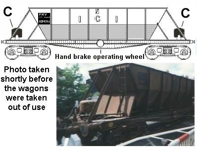
The LNER/BR vacuum operated clasp brake
was an asymmetric design, on one side there were two V hangers, on the other
there was a rectangular arrangement to allow the use of a standard brake handle
(this can be seen on the Peco fifteen foot chassis). Although this was the
official standard there seem to have been a lot of vacuum braked wagons built
using standard Morton pattern brake gear so I wouldn't worry about this unless
you fancy messing about to add some variety to a rake of wagons. If you decide
to modify a chassis do check with photographs to make sure that some wagons you
are working on did use this kind of brake.
Fig___ LNER and BR
standard vacuum brake gear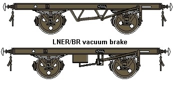
Failure of Continuous Automatic
Brakes
In theory a train fitted with
continuous automatic brakes cannot accidentally leave any wagons behind as if a
coupling fails the brake pipes should separate and apply brakes on both parts
of the train. However Messirs David Hansen, Clive Feather and 'Chippy' have
discussed three incidents involving 'fully fitted' trains on the uk.railways
news group. The oldest occurred in the later 1950's when a goods van (possibly
two) was left behind on the East Coast Main Line around Montrose. This must
have been tagged on to a passenger train as there was no mention of a brake
van, brake vans were still mandatory for goods trains but, thanks to the safety
of the continuous automatic brake, individual vans could be attached to
passenger trains (four and six wheeled 'fitted' stock were only banned from
passenger trains in 1959). The train came to a halt but the train crew, and
staff on the line following the incident, failed to realise that the van(s) had
been left behind. By the time this was spotted by a signalman another train was
already in the section and it ran into the van. In the 1970's a loaded steel
train found itself on the gradient at Beattock with only the brakes on the loco
operating. The train accelerated and ran into the rear of the preceding train
(also a steel carrying train) with enough force to kill one of the crew. More
recently a Freightliner rake parted, the brakes were not activated and the rear
portion of the train then rolled along under its own momentum into Carlisle.
The signalman saw what was happening and diverted the errant wagons onto an
avoiding line around the station but the wagons then derailed and demolished a
bridge, some of the wagons ending up in the river. Apparently the full brake
test had not been completed when the trailing section had been added to the
train at Preston. I do not have details of exactly what occurred in each of
these incidents however the assembling of a 'fitted' train requires that all
the pipes (air or vacuum) are connected and that the stop cock valve on each
pipe is opened. The valve being closed would prevent the brakes operating on
any of the following wagons but any stock between the closed valve and the loco
would function as intended. Crucially everything would appear normal to the
train crew. If the train was on a gradient, as with the steel train, only the
locomotive brake and any wagons connected to the loco with the cocks open would
function. If the train parted at a point beyond the closed valve, as with the
Freightliner incident, the train would continue as normal and as the brakes
would never have been charged the loose wagons would be free to roll. This
appears to be the basic cause of the second two incidents, however another
contributor noted that he had seen a fault on an air braked vehicle where the
hose became blocked and remained filled with air even when removed from the
wagon. Regarding the steel train incident the contributor signing himself
'Chippy' added
I can't recall the Beattock incident, but a continuity test should have prevented such an occurrence. The only other possibility would be a incident such as that which happened at Darlington to a Deltic-hauled passenger train, when the brake-pipe cock was knocked closed by an object thrown up from the track. The train was signalled into the platform at Darlington, and was heading for the divergence without noticeable reduction in speed. A restaurant car steward realised that the train was not slowing, and used the communication cord.
The cocks mentioned can be seen in the photograph at the end of the
section on Goods Rolling Stock Design - Chassis - Couplings & Hoses. This
photo shows the hoses associated with an early BR twin-pipe air brake and the
standard vacuum brake.
Braking
Developments under BR ownership
Following nationalisation British Railways initially stayed with the vacuum
brake and this was included in the 1955 modernisation plan as a requirement for
all new stock. By the early 1960's with heavier goods stock entering service
the design of the standard British Railways vacuum brake incorporated a
facility for automatic changeover for loaded and empty working. Longer
wheelbase wagons with this feature have an arm extending toward the centre from
the left hand brake shoe, this can be seen on the Peco fifteen foot wheelbase
chassis. Following comparative trials of air and vacuum brakes in the 1960's
the decision was made to change over to air brakes. All new stock built after
1971 was equipped with air brakes. Air brakes then had to be retrofitted to
older vehicles when these were to travel in new high speed air-brake only
services. This did not please the rolling stock leasing firms and the oil
companies who owned their stock and had to foot the bill for the change over.
By the early 1970's vans and open wagons
equipped with air brakes began to appear in sufficient numbers to allow the
development of a network of air braked services. These vehicles were designed
to run at 60 mph fully laden and could travel at 75 mph with a reduced load.
The first all air-brake wagon load services began in 1972 and air-braked
'cartic' car transporters displaced from Motorail services were soon included
to carry imported cars.
Some vehicles were
built or modified with both vacuum and air brakes ('dual fitted') but this was
not common. About three hundred ten foot wheelbase 'vanwide' vans and a smaller
number of twelve foot wheelbase 'pipe' wagons were modified in this way, mainly
to handle for Ministry of Defence traffic. An alternative was to add through
pipes for air brakes to vacuum fitted stock, this was much cheaper and was much
more widespread. A number of air-braked vehicles were also fitted with a
through vacuum pipe (quite a few privately owned four-wheeled air-braked tanker
wagons were so fitted and TOPS coded TTB). In late 1987 a number of twenty one
ton end door wagons (TOPS coded MDV) had through pipes for air brakes added
(re-coded MDW), these wagons were then used for coal and scrap metal in
Scotland.
A lot of vacuum braked wagons
continued in service into the late 1980's, the ubiquitous twenty one ton coal
hopper (TOPS coded HTV) were still in use for coal, sand and crushed limestone
(supplying tar macadam plants) up to about 1991. The twenty one ton steel
mineral wagons coded MDV remained in use in South Wales moving coal and
colliery spoil until about 1992. Some of the more specialised vacuum braked
stock survived a lot longer than anyone expected. The ICI owned limestone bogie
hoppers built in the 1930's were kept in service until mid 1998, although the
vacuum fitted locomotives able to haul them were getting scarce and pairs of
class 37's were the norm.
After 1996
unfitted trains were banned by Railtrack, and by this time many locomotives had
only the facility for air braking fitted. This was a problem when dealing to
the movement of old vacuum braked wagons, vehicles being sent to scrap yards or
damaged stock being taken for repair. The solution was to break the rake up
into three wagon 'cuts' with redundant HAA hoppers inserted between the cuts.
The brake pipes on the HAA wagons are then connected using a long flexible
hose, allowing them to be used to control the train.
The general trend has been to switch to disc brakes on more
modern air braked stock (many of the modern wagon types use disc brakes), but
Freightliners Ltd. when looking at replacement designs for the now ageing fleet
of container flats in the late 1980's stated they were not interested in disc
brakes, considering that the cheaper clasp type are perfectly adequate for
their purposes. Clasp brakes remain the most common type on goods stock
throughout Europe.
As discussed in the
section on Track there has been a Europe wide study on the reduction of noise
pollution caused by freight trains. One part of this study was the Eurosabot
project, focusing on the design of the brake blocks used on modern tread
brakes. The idea was to look at alternatives to cast iron for the brake shoes
to reduce the damage done to the treads and hence the noise they make as they
roll along and also to reduce the squeal when the brakes are applied.
Thermo-elastic instabilities due to local heating of the contact surface and
material transfer between block and wheel, dynamic instabilities and periodic
wear were felt to be factors responsible for the generation and growth of
roughness on the wheel treads. In the end no practical alternative to cast iron
was found.
Adding vacuum brakes to a model chassis
The Minitrix ten foot wheelbase chassis has the large
cylinder for the standard British vacuum brake system moulded onto the under
side. Parkwood Models kits come with a brake cylinder that can be fitted if
required but Peco, Farish and many kits using these chassis need a home made
cylinder adding. The brake cylinder, when mounted under the wagon, was offset
to one side and offset to the left of the V hanger. The Parkwood kits suggest
mounting the cylinder on the letter P in Peco, moulded on the underside of the
chassis kit. I have tried various methods for adding these brake cylinders. One
method is to cut a length of empty ball-point pen refill, pass a lengths of
Slaters 20 thou brass wire through this and pack it with Milliput, keeping the
wire central as possible. One end of the wire is trimmed to about 2mm length
and this is glued into a hole drilled in the bottom of the chassis (I use the
tip of a pointed modelling knife to bore the hole). The trailing end of the
wire is bent over into a square U shape and the free end is glued into another
hole in line with the V hanger. A simpler method is to use a spare Peco
wheelset, trim off the flange (I use toe nail clippers for this) glue the rear
of the wheel onto a scrap of 30 thou card and trim this (you do not need to be
very accurate here). The card backing is then glued onto the underside of the
chassis. You can drill a hole in the centre and add a wire U shape as before,
or you can just glue a strip of 20x20 thou to the wheel to represent the
operating lever that connects to the cross linkage between the V hangers. The
Peco wheel is actually rather large in diameter but in normal use it is almost
hidden under the wagon. Both methods are more fully discussed in the section on
Kit Bashing.
Fig___ Vacuum brake
cylinders on model chassis
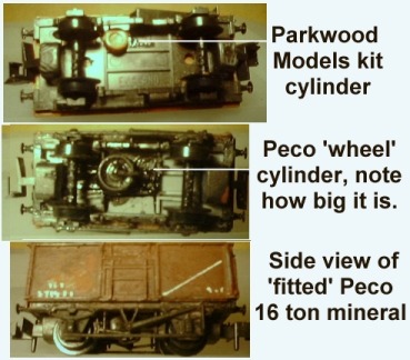
On hopper wagons it was not possible to have a cross linkage
allowing a single vacuum brake to operate on both sides of the wagon so two
reservoirs were commonly fitted. As these could not usually be accommodated
under the wagon they were usually mounted on top of the chassis tucked under
the end of the hopper at one end of the wagon. This can be seen on the Peco
Grano and Farish hopper wagons. On bogie wagons it was usual to have a
reservoir at each end, one for each of the bogies, and on hopper types these
were again mounted on the top of the chassis. The sketch of the ICI limestone
hopper shows the cylinders (shaded dark grey) mounted at each end of the
chassis (c).
Fig___ Vacuum brake
cylinders on a bogie chassis
The hand brake was still required for use when the vehicle
was not connected to a locomotive and on four wheeled British stock the
automatic brake was commonly connected to a standard four-shoe Morton pattern
mechanism on 'fitted' goods stock. The vacuum brake piston operated a lever
which turned the cross-linkage between the V hangers to apply the brakes. The
connection to the cross link rod was fitted with a ratchet mechanism so the man
applying the hand brake did not need to overcome the force of the return spring
in the vacuum cylinder.
The principal
disadvantage of continuous automatic brakes, air or vacuum, is that when a loco
is not attached to the stock the brakes will be on. As a lot of shunting was
done by men and horses or by gravity the automatic brakes had to be disabled so
the wagon would roll freely. The pressure in the onboard reservoir cylinder was
released by pulling on a short chain under the wagon. The location of this
chain was usually indicated by a five pointed white star painted on the
chassis.