Cement manufacture and distribution
Sand-Lime Mortar is, as the name suggests, lime and sand mixed with water on site (for details on sand and lime production see under Quarries). As the mortar mixture dries the lime absorbs carbon dioxide from the air and becomes a solid rock-like material. Further wetting does not reverse the process but the process needs the carbon dioxide from the air and so mortar cannot set under water. Modern cement is different, it sets under water, it is a lot stronger than mortar and serves well as an outer coating or 'render' on other building materials (used to cover brick it can be carved to represent stone blocks). Modern cement can be used to make small structures, although these are not very strong, however when mixed with sand and gravel it forms concrete which can be used to make large structures. The Romans knew about cement and concrete but the secret was lost until the eighteenth century when it was re-discovered over a number of years.
Cements used by the Romans and in Middle Ages Europe seemed to be unusually strong, this was due to the use of local materials which contained trace elements. At Pozzuoli in Italy they used the local volcanic ash, producing a very strong cement. In the 1750's the builder of the Eddystone lighthouse, a Mr. Smeaton, needed a better cement than simple lime mortar and by chance a local merchant had imported some of the pozzuolana lime from Italy and Smeaton was able to use this (mixed with blue lias lime) to make the cement for the lighthouse. Smeaton also developed an improved mortar by adding brick dust and used this to make an early form of concrete by adding pebbles to the mixture. It was then realised that the key to the strength of the cement was the mixing of clay with the limestone or chalk.
Early cements were very similar to mortar, they were based on naturally occurring materials such as chalk marls heated in a kiln to produce a dry powder (marl is a mudstone rock containing roughly equal amounts of both clay and calcite). This early form of cement was sold as Roman Cement, one centre of production being Northfleet, Kent. A chap called Frost patented an improved mix he called 'British Cement' in 1822 and set up his works at Swanscombe. In 1824 a Mr. Joseph Aspdin (1779-1855) a mason of Leeds patented the first totally artificial cement which he called 'Portland Cement' as it resembled white Portland stone. This was produced by bruning a mixture of clay and limestone and drinding up the resulting materials to form a powder. Aspdin set up his works at Wakefield and at Gateshead and within ten years a man called Charles Johnson improved on the process by heating the ingredients to a white heat so they fused together to form a 'clinker' which was then ground to a powder to produce the first modern cement.
Modern cements are made by fusing together limestone or chalk with clay, shale or river mud, all of which is ground to a fine powder. This is then mixed with water to form a slurry, the materials have to be very fine (the filters on the feed to the slurry tanks have 29,000 meshes per square inch). The slurry is then fed into a kiln where the water is driven off and a chemical reaction takes place, fusing the ingredients together into a powdery mixture.
Outline Histroy of the British Cement Industry
Firms set up wherever chalk or limestone were available and in the 1840's an improved mix, using three parts limestone to one of clay, was introduced. Although not everyone made clinkered Portland cement this became dominant by about 1900 by which time there were fifty or sixty firms operating, producing well over million tons a year between them. In that year the first major reorganisation of the industry took place with twenty four firms combining to become the Associated Portland Cement Manufacturers Ltd. The individual trade names were retained to maintain the good will of consumers, but there was a trend toward a uniform quality based on improvements from jointly funded research. In 1912 the majority of the remaining manufacturers agreed to combine to form a group called The British Portland Cement Manufacturers Ltd.
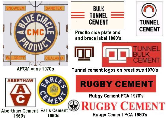
In 1920 a new organisation was formed, the Cement Marketing Company Ltd. who's sole purpose was the disposal of the products of A.P.C.M and B.P.C.M. It was the formation of the CMC which saw the introduction of the Blue Circle logo, and all cement produced by the two companies is now sold as Blue Circle Cement. When I did the original research on this in the mid 1980s I found several pictures showing the blue circle logo with the letters CMC in the centre, at the time I arrived at the conclusion that the words 'blue circle' only appeared in the 1950s. This was based on material loaned by Blue Circle themselves (which I then returned to them). More recently, when tidying the section up, I have photographs dating back to the 1930s with the words blue circle inside the ring. Just to further complicate matters a lot of the railway wagons and hoppers seem to have had a plain white centre to the logo. Once I can make sense of this I will tidy this page up.
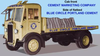
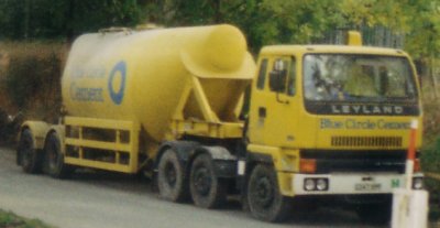
The lorry shown below was photographed in 1939 and clearly has 'blue circle' inside the ring. The lorry itself is an Albion and had a top road speed of 20 mph. When in transit the load would be covered by a tarpaulin.
Fig ___ Blue Circle lorry in 1939
Further reorganisation took place in the 1920's and 30's, and by 1950 the A.P.C.M. group owned some twenty six cement works, twenty four of which were producing a variety of products including lime, whiting, cement paint, gravel, decorative finishing and paper bags. There were other firms producing cement, the Aberthaw and Bristol Channel Portland Cement Company, which purchased the rival Aberthaw and Rhoose Point Portland and Lime Company in 1919 was bought out by Blue Circle in 1983. ICI operated cement plants at Billingham Co Durham and Tunstead (near Buxton, now owned by Tarmac Buxton Lime and Cement - now part of the Anglo-American Group). Ketton Portland Cement were based in Rutland and Tunnel Cement had works in Flintshire, Bedfordshire and Essex. Rugby Portland Cement had seven cement works in the south of the country, the northernmost being in Lincolnshire.
The recession of the 1970's hit the industry very hard, production collapsed from twenty million tons per year to only just over twelve million tons per year. This resulted in a general reorganisation of the industry with consequent closure of smaller factories and the building of new larger establishments to gain the benefit of the economy of scale. Up to the 1980's the cement making process remained basically unchanged, in the South the basic materials used were chalk and clay, in the North limestone and shale.
By the 1980s three large groups dominated the British cement industry, the largest was Blue Circle accounting for over half the total production (Blue Circle was taken over by the French Lafarge group in 2001). Tunnel, Ketton Portland Cement and Ribblesdale Cement (itself a joint venture set up by Ketton and Tunnel) were absorbed by Rio Tinto Zinc (RTZ), they were merged into a single entity called Castle Cement from 1986, it was then bought by the investment firm Hanson which was taken over by the German firm Heidelberger Zement in 2007 and the third player was the then independent Rugby Cement, now owned by the Mexican giant Cemex.
By the early 21st Century there were just four companies operating a total of 15 works (with a total of 19 kilns) in the UK. The companies were Lafarge Cement Ltd with 7 plants, Tarmac Buxton Lime and Cement with just one plant, Cemex UK Ltd with 3 plants, Castle Cement Ltd with 3 plants and Quinn Cement who operate a single plant in Northern Ireland. The UK industry was still producing some 15m tons of cement a year however, the output from each modern kiln having been increased by some 500% on the figures for the mid 1960s.
Fig ___ Cement company logos
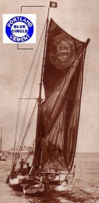
Originally most cement manufacture was based in the South of England close to deposits of the raw materials (mainly chalk) used in its manufacture, but by the early 20th century there were cement factories and depots all over the country. Although considerable quantities of cement has been moved by rail water transport was also widely used for coastal as well as international trade. In 1926 the A.P.C.M. had a fleet of some 156 sailing barges operating on the Thames & Medway with the blue circle logo on their sails however by 1950 only a single sailing barge was still on their books. The picture below is (I believe) that lone example, note that the logo on the flag and sail has the words Blue Circle rather than the initials CMC.
Fig ___ Cement Barge
Cement Manufacturing Process
The limestone or chalk is crushed and mixed with the clay and water in a 'wash mill', the resulting slurry is then stored in mixing tanks from where it is piped to a kiln. In the kiln the slurry is heated to drive off the water and the material fuses to form dry pebbles of glass called 'clinker'. The rubble like clinker that emerges from the kiln is then ground and mixed with gypsum (which prevents the cement from setting too quickly) to form cement powder.
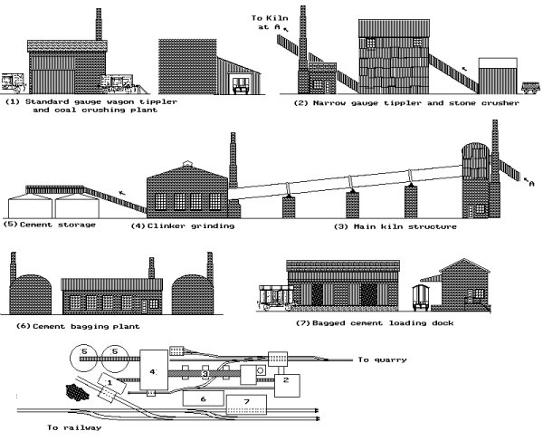
A small cement works would require a space of about eighteen inches by six inches in 'N', the raw materials could be brought in from a quarry off-stage along a narrow gauge railway. Since about the 1950's the rock has been crushed at the quarry itself and pumped as slurry to the factory but this is of little interest in the present context. Once the local quarry was exhausted the materials were often brought in by rail as this is cheaper than re-locating the factory.
Assuming the rock is delivered direct to the works you will need a crushing plant (steam powered stone crushing machines were introduced in the 1860's) and a wash-mill. The crushing plant would be located where the stone and clay arrived, a small building will do for that, say an inch by two inches (25mm by 50mm) and about one and a half inches (38mm) tall with two or three small windows, one of which would be near the top. Corrugated iron cladding was a feature of most stone crushing plant. Attached to this would be a small boiler/engine house with its associated chimney.
The wash-mill would require another building of similar dimensions, adding a raised water tank helps identify its function. The slurry from the wash mill was piped into storage tanks, by the 1930's these were circular and made of concrete (see Fig ___).
Early cement makers used bottle kilns (as used for pottery), in the 1840's they moved on to using rectangular buildings in which the kiln was in the lower part and the slurry was laid on the floor of the space above to pre-dry it before firing. The vertical of shaft type kiln was in use by the 1860's (see Furnaces and Kilns) but in the 1880's the first continuous process rotary kilns were built. The rotary type proved much more economical and soon replaced earlier manufacturing methods.
The rotary kiln consists of a long metal cylinder with teeth inside and cogged rings at intervals on the outside. The external cogged rings engage in powered gears which rotate the tube slowly. The tube is inclined so the rolling mix slowly moves down to the other end. One early rotary kiln (built in about 1887) was five foot in diameter and only twenty six feet long, quite soon however they were typically six to eight foot in diameter and between sixty and one hundred feet long. By the 1950's they had grown to ten or twelve foot across and up to three hundred foot in length.
Powdered coal was used as the fuel, about eight hundredweight being used to produce a ton of clinker. The pulverised coal is blown in through the centre of the tube at one end and burns, filling the centre section of the tube with hot gasses at about 2500 degrees Fahrenheit.
The rotary kiln makes an interesting model, for the main body use a length of wooden dowel or plastic tube between half an inch and an inch in diameter (12-25mm) and about 10 inches to a foot long (25cm-30cm), paint dark brown and add 'rusty ' patches. This tube was mounted at an angle of about fifteen degrees and supported at intervals of about two inches (50mm) on brick or stone piers. The piers had wheels mounted on top and the tube had a guide rail to run in these wheels.
The piers can be built from brick paper wrapped wooden blocks and a length of wire wound round the tube would do for the rails to fit the wheels. Somewhere between a third and half way from the lower end of the tube there was usually a larger pier supporting both the tube and a building with a chimney. This secondary building should be about an inch long (25mm) by two inches long (50mm) and the chimney should extend about an inch (25mm) above the top of the roof.
At the upper end of the tube there was a tall building with an even larger chimney, the tube entered this building through a close fitting opening in the upper wall. A plain block of wood would do for the basic structure, wrap the lower part in brick paper and sand away part of the top so that Ratio corrugated walling sections can be fitted to represent the point where the mix is tipped into the hot tube and the gasses are allowed out.
At the lower end the tube passes through a large opening into a big building with roof ventilators and a tall chimney.
The building was usually of the 'shed' type, a wooden or metal framework with a lightweight cladding but some were brick built, which might be easier to model. The clinker emerging from the kiln was broken up in the large building at the foot of the tube and the resulting powdered cement was then stored in cone-topped buildings. The best bet here is to use the top of a small washing up liquid bottle with side walls about half an inch (13mm) high as shown in Fig ___.
The bagging was done in a large building with quite a few windows, there are several factories' available as kits but to avoid mixing embossed brick and brick paper in a single scene I suggest you use a Ratio corrugated roof for this, adding walls and ends from thick card with brick paper covering.
The bagged cement was loaded into vans at a platform large enough for three or four vehicles. The product had to be kept dry of course and but the examples I have seen from the 1920's and 30's used an open platform with a large awning, but you could use a 'goods shed' for this building, eliminating the need to model the bags. Fill in the empty spaces with smaller ancillary buildings and clutter.
Fig ___ Cement Works
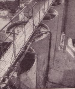
By the 1940s the cement works were pre-mixing the raw materials with water to form a slurry to be pumped into the kilns, the slurry was stored in tall cylindrical silos close to the kiln and I was fortunate enough to find a photograph showing the tops of these tank.
Fig ___ Cement Slurry Tanks
Since the 1970's the 'dry kiln' process has been developed which has rapidly replaced the older method. The dry system, being a modern development, features works which are mainly enclosed in large buildings. This makes for easier modelling but unfortunately the modern works tend to be somewhat large for the average layout.
In the conventional system the chalk/clay mix has to be turned into a slurry with water before being fed into the kiln, which requires more energy as the water has to be boiled off in the kiln itself. In the dry kiln system limestone and clay or shale are delivered to the works where they are crushed down to about the size of marbles and stored in a series of segregated hoppers. From the hoppers the two materials are passed through a dryer which resembles the kiln described above (although as noted it is usually inside a building these days). After drying they are mixed by weight and then ground down to powder form (called 'raw mix'). This mix is then blended to make 'meal' before being poured into the rotary kiln (again usually inside a building these days). The kiln is heated to nearly three thousand degrees Fahrenheit at which temperature the mixture fuses into small pebbles of clinker.
The clinker is then mixed with gypsum and the mix is then ground to make Portland cement powder. The powder is stored in silos (these days the silos are often metal tubes, sometimes built inside a square or oblong building) and it can either be bagged or shipped out in bulk.
This process requires limestone as such (chalk cannot be used) and as there is no limestone in the south of the country the railway carries considerable bulk loads from the quarries of the north.
Clinker is sufficiently high value to warrant shipping to remote finishing plants. Clyde cement (a trade name for Ribblesdale Cement) built a new plant at Clitheroe in Lancashire in the late 1970's and in the 1980s they commissioned a fleet of 88 ton glw bogie presflow type tank wagons (rather resembling bogie gas tank wagons) for powdered cement and a further fleet of 88 ton glw hoppers to ship clinker up to Scotland.
Cement was moved in hessian cloth sacks up to the early 1920's, resulting in a great deal of dust and staining of wagons and loading bays used for the traffic. PO wagons and in particular vans (illustrated below) were widely used as the railways could refuse to carry cargo which would damage their rolling stock. Since about 1930 the vast majority of cement has been shipped in paper sacks, those used for export being of the five or six layer type. These greatly reduce the staining and associated damage to the rolling stock so the railways often provided vans for this traffic.
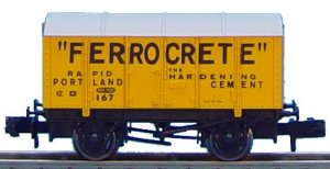
PO vans, which would be stained with the powder, remained in regular use however, the 'iron mink' type vans were popular for this work. Dapol offer such a van in PO cement livery and the N Gauge Society offer a kit of this van with cement livery transfers. The photo below is courtesy and copyright Dapol.
Fig ___ Dapol Cement Van
These could be parked at a convenient siding near a job and served as a store for the sacks whilst work progressed. One type used in the 1930's had what appeared to be ribbed metal sides and a peaked roof, I have not yet found a sufficiently good photo to attempt a drawing but something could be produced based on the Peco 'salt' wagon, adding new sides from 20 thou card with ribs added from 10x10 thou strip.
Fig ___ Cement Vans and Presflo liveries
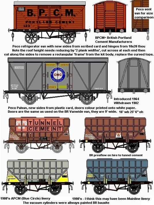
Export cement was often shipped either in bulk or in small wooden casks (weighing in at 6 to the ton) up to the mid 1940's when the steel cask was introduced. These came in two sizes, the small ones being about half the size of the larger which are similar is size to a standard 45 gallon oil drum. The cement drums are rather like oil drums in appearance but have a series of evenly spaced ribs on their sides. The drums are painted with bright enamel paint on their sides, white, silver and dark grey being the principal colours, on the larger type the top and bottom are usually white and marked with the company logo, on the smaller drums the logo is on the sides and the ends are painted the same colour as the body. I am not sure if the drums are still in use, they were in the 1970s. The sacks and drums are often made by the cement firms, which are now very large industrial combines.
Bulk cement is these days stored in tall cylindrical silos, discharged by gravity or sometimes pneumatically into wagons resembling tankers, the Grafar Presflo, Lima Prestwin and Peco 15 foot wheelbase tank wagon might all serve for such stock but the most popular in the 1980s was the depressed centre tank available from Graham Farish.
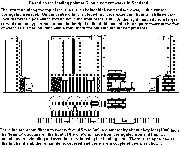
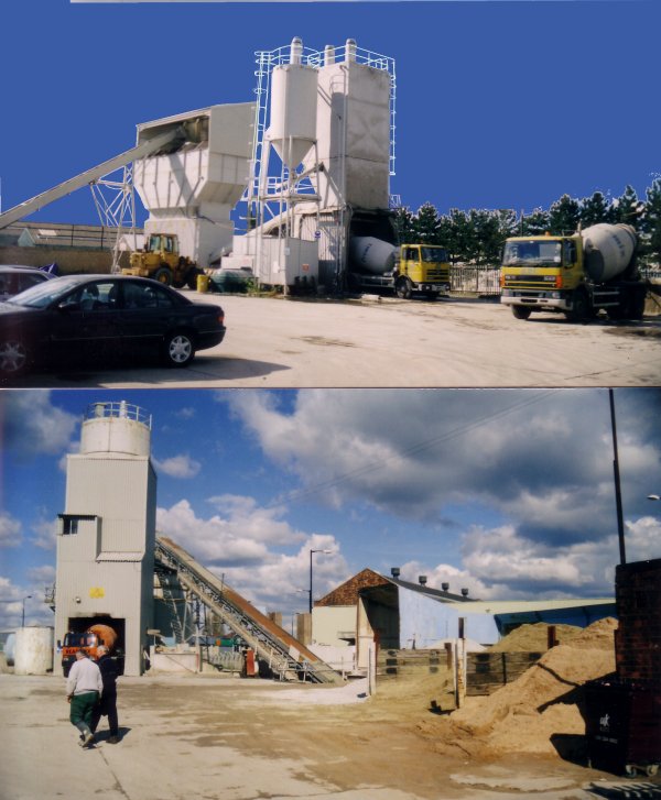
Fig ___ Modern cement loading silos
Incoming cargo to a cement works would include limestone or chalk (itself a form of limestone) and clay, from the nearby quarries, often supplied by conveyor or in narrow gauge tipping trucks. This former arrived as half brick sized rubble and was further crushed at the factory.
There would be wagon loads of imported gypsum rubble, which is white in colour and produces quite a lot of dust, and coal. The coal was usually crushed to powder at the cement works rather than shipped in as pulverised dust. Pulverised coal recovered at the coal mine was shipped in sheeted open wagons or in roofed wagons similar to the Peco five plank 'Salt' wagon. In the BR era rakes of five or six sheeted sixteen ton mineral wagons might be seen delivering pulverised coal to the works.
One option is a simple cement depot, receiving supplies of powdered cement by rail (vacuum braked Graham Farish 'Presflo' wagons or modern air braked 'Cemflow' stock) and despatching the stuff by road tanker. The sketch below is based on the installation at Northenden on the old CLC line from Stockport to Altrincham.
Fig ___ Cement depot
The silos were built in the 1960's and were supplied using Presflo wagons up top the 1970's, more modern air braked wagons were then introduced and these replaced the Presflo's by the late 1980's. The cement was sent out in road lorries equipped for 'presflo' operation, these had a cylindrical tank with a domed end behind the cab and a tapering cone, angled downwards at the rear.
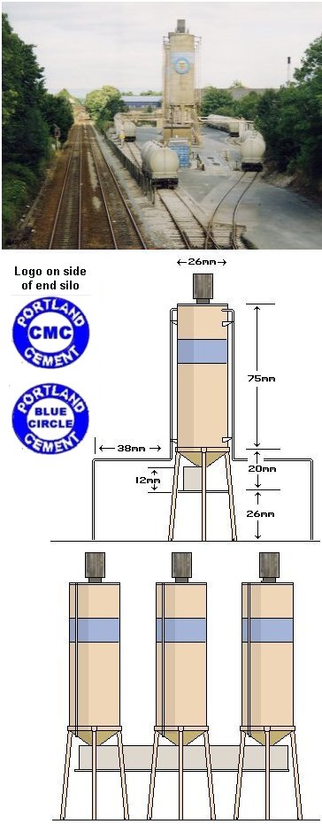
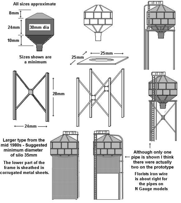
The silo's are not difficult to make, the standard plastic tube used for Steradent tablets is ideal, it is the correct diameter (26mm) and you get two silo's from a single tube. The cone shaped base can be made using paper rolled to shape and glued or you could cut down a 'party popper'. The enclosed walkway is about six feet high and about four feet wide, running along the base of the silos. The silos are made of concrete rings and stand on concrete bases.
The general dimensions are as shown in Fig ___, you can change things to suit the materials you have to hand but the silo diameter should not be less than about 16mm or more than about 30mm. The walkway running along underneath the silos has an enclosed structure mounted to one side which houses the discharge gear. This has corrugated walls but for modelling purposes 1mm scribed plastic card would look well, with a roof of plain card. The roof angles down to the outside so rain will not drain onto the walkway. Note there are handrails (Plastruct) on both sides of the walk-way although one set is up against the outer wall.
The supporting legs should be square section tube 3-4mm wide. The unit mounted on the top of each silo can be made using a 10mm length of the same tube you used for the legs with some florists wire looped round and through. Seal the top with Milliput and add a top plate from plain card and a base support from a 3mm length of the same square tubing.
The cement pipes (x) should be about 1mm in diameter, florists wire is rather soft and might get damaged in this application. A better bet would be brass wire which can be obtained from your local model shop. Note they are held some distance from the silo wall, about 4 or 5mm should look okay, and they extend over both the road ways to either side and also over the railway tracks (Fig ___(B).
Fig ___ Close up of cement silos
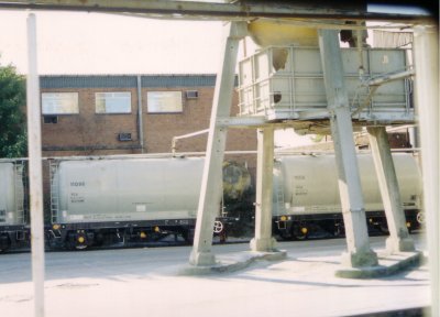
The silos all had a four legged base, the scale can be judged from the railway wagons.
Fig ___ Northenden silo supports
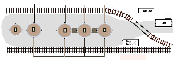
At Northenden there are four silos in a row, then a gap (about two silos in size) followed by two more silos, the last silo is considerably smaller than the rest. How many you build is a matter of how much space you have but I would suggest three full size ones is a reasonable minimum.
Fig ___ Layout of road access to cement silos
The silo's are painted a faded yellow (Humbrol 'sand' or 'light earth' would be about right), there is a faded blue band as shown and the end silo facing the weighbridge has a circular plate 12mm in diameter with the Blue Circle logo. For layouts set in the 1950's or 60's this can be quite easily made from a disc of 20 thou card or post card, paint a blue ring with a white centre and add the letters CMC in black in the middle. For more modern layouts the lettering disc is still white with a blue band at the outer edge but the lettering (again in black) is BLUE CIRCLE CEMENT, arranged in three lines. This is much more difficult to make in 'N' but you could make a coloured drawing to a larger size and reduce it on a colour photocopier.
The cement pipes, the walk-way and its handrails are the same faded sand colour as the silo. The structure enclosing the discharge apparatus on the walk-way is painted light grey and the unit on top of the silos is painted dark grey, almost black.
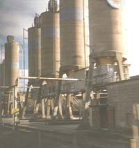
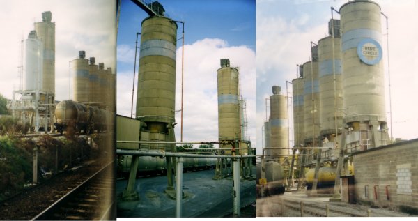
I repeatedly tried to obtain photos of this depot from passing trains, however the light was always difficult, the examples below are the best I have so far found. Note that the final silo (shown in the picture on the left) is smaller than all the others.
Fig ___ Northenden silos
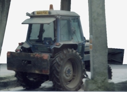
If the wagons needed rearranging for any reason a shunting tractor was available in the yard, usually left parked out of the way under one of the silos.
Fig ___ Cement terminal shunting tractor
The lorries drive in and park alongside the line of silos where they are filled using a flexible hose. The cement was sent out as a powder to local ready-mix plants in the area.
In the later 1960s or early 1970s a lightweight metal gravity feed silo appeared in some numbers at the ready-mixed cement depots and also at some power supply depots. The early examples were supported on an open metal framework, by the early 1980s this was usually encased in corrugated metal cladding as shown in the sketch below. The silo itself is an awkward shape, otherwise the model is easy. These were positioned close by the railway siding, there would be a small brick or corrugated iron shed close by housing the compressors and pumps.
Fig ___ Gravity feed silo
The presflo wagons
were originally designed to be unloaded into road lorries (themselves fitted
with a 'pressflo' body) in goods yards for delivery to the mixing site. The
unloading was accomplished using heavy, dark grey, reinforced rubber flexible
hoses about four inches in diameter. Coiled-wire guitar Bottom E strings
painted dark grey would serve for these hoses in N. The compressor used to provide
the air for the system was a fairly standard type, usually a two-wheeled
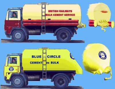
trailer type machine, and these can be knocked up from scrap. In the terminal there was an on-site compressor in a separate building. The sketch below shows the early BR owned lorries used for this traffic (they operated from BR goods yards using a portable wheeled compressor) and a later PO lorry with a distinctive tapering back-end to the silo. Lorries of this general outline with the tapered rear to the tank, but some much larger and running on up to eight wheels, continued in use into the 1980s (possibly the 1990s)
Fig ___ Cement lorries
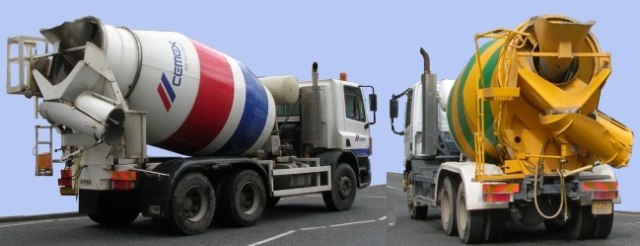
The photo below shows the type of large articulated lorry used for the powder traffic in the later 1980s.
Fig ___ Typical large lorry used for deliveries of cement powder in the 1980s
Although Portland cement is the main product we also use a lot of Gypsum cement, commonly known as plaster. Gypsum (otherwise known as alabaster, plaster of Paris or natural hydrated calcium sulphate), is also added to portland cement to control the rate at which it sets. Gypsum is used for making fertilisers, paints, plaster, and in mines and iron foundries as well as for cement.
Cement based on gypsum is used in the production of 'plasterboard' used for ceilings and 'stud walls' in modern houses (in older houses a mix of plaster a horse hair was applied to wooden laths nailed to a wooden framework).
Gypsum rock is a white stone imported from Ireland. It was shipped in bulk in two to four inch lumps. To make gypsum cement it is cooked to drive off some of the water it contains.
Concrete
Concrete is cement with gravel (or stone chippings) and sand. When mixed with water the mixture sets in a complex chemical process, not yet fully understood, shrinking slightly as it does so. The most common mix is 1 part cement, 2 parts sand and four parts gravel or crushed stone, this is known as a 1:2:4 mix. Where greater strength is required the amount of cement (the most expensive element) may be increased to give a 1:1:2 mix, where strength is less of a factor a 1:3:6 mix may be used.
During the Second World War cheap concrete with a high proportion of alumina was used for building fortifications on the coasts, after the war it was found that this had hardened far more than had been expected, and it was hailed as the new wonder material. Unfortunately it was only after several tower blocks had fallen down that it was realised that exposure to sea water was a major contributory factor to the strength of the material.
In Europe the French were at the forefront of designing concrete buildings, the Americans were enthusiastic about the stuff. Concrete has limited tensile strength but in 1867 a French gardener by the name of Joseph Monier though of adding a metal mesh and produced reinforced concrete (sometimes called 'ferro-concrete'). Monier wanted to build very large flower pots but engineers were quick to spot the potential of his idea. By the 1880's people in Germany, France and Austria had solved the design problems and practical methods of reinforcing concrete with steel rods and girders had been developed.
Later someone thought of tensioning the rods while the concrete set and gripped them, producing pre-stressed concrete. Unfortunately no one has yet thought of a way of releasing the tension in pre-stressed concrete other than explosively by cutting the beam, when the concrete disintegrates as the steel contracts and flies off like shrapnel. Disposal of structures built using pre-stressed concrete is presenting some interesting challenges to demolition experts the world over.
Pre-stressed concrete has been used in the construction of large bridges and buildings since the 1870's but it did not really catch on in Britain until the mid 1920's. Large structural beams were shipped on railways, usually with the ends of the steel rods sticking out at either end.
The early railways saw the potential of concrete structures and made use of it in their buildings from about the time of the First World War. Since the 1920's concrete has been extensively developed and a wide range of items have been produced from it to replace stone equivalents, such as kerb stones, building blocks and railway sleepers, it has also been used to replace steel spans in bridges and buildings.
The Southern Railway favoured the use of concrete prefabricated structures, platforms, footbridges, signal boxes and even its small line-side huts being built in this way. Some railway companies in the North East used concrete signal masts (see Fig ___). Since the late 1950's railway sleepers have been produced from this material, and would form an unusual wagon load for ones system.
The first recorded use of ready mixed concrete delivered to site was in 1913 in the United States of America, the first British plant was set up in 1931. Take up was slow until after the Second World War, building rapidly in the later 1950s. Ready mixed concrete production in 1950 was no more than 150,000 cubic metres increasing to
6-5 million cubic metres by 1961 and production peaked at 31-6 million cubic metres in 1973. By the early 1980s production had declines somewhat. Ready mixed concrete was not shipped by rail as it has to be mixed en-route and would require transshipment at the receiving end to the building site. In the present context however the raw materials for its manufacture can be shipped into the mixing plant by rail. Presflo type cement hoppers, stone chippings in hopper or tippler wagons and sand in steel tippler wagons.
The most common type of silo used to load cement into the ready-mix lorries is much smaller than the cement storage silos discussed above. Those I have seen have been put up to handle traffic for a specific job are not intended to last more than a few years at most.
Fig ___ Post war Ready-Mixed Concrete Depot
The sketch below left shows an early cement mixer lorry, up to the 1960s these had a separate engine for rotating the cement drum. The spit windscreen with wrap round corners date this machine to the later 1950s or early 1960s but similar lorries with an earlier style of cab were operating in the 1940s. By the mid 1970s the lorries were tending to get larger and the drum was larger in proportion to the lorry. The sketch in the centre shows a lorry fitted with a light weight hydraulic mechanism for rotating the cement drum, taking its power from the lorry engine. The cylindrical tank on the top of the turning gear is the hydraulic oil header tank. On the right is a sketch showing the rear of a machine, this machine dates from about the 1990s, note there is a conical hopper at the top, used for filling at the depot, this hopper was introduced (I believe) in the 1980s. Also shown is the feeder channel, this has two sections. In transit the bottom end is folded up and over to rest on the upper section, this is then hinged to lie across the rear of the vehicle.
Fig ___ Concrete mixer lorries

Fig ___ Concrete mixer lorries in transit
Ready mixed concrete has to be poured within a couple of hours or it will start to set, so the depot will only supply an area of perhaps 5m radius in built up areas, 15m or so in more rural locations. As a result there are over a thousand ready mixed depots around the country, most in urban areas. By the year 2000 roughly 70 per cent of concrete used on site is provided by the ready mixed concrete companies. Mixing on site now tends to be undertaken either by consumers needing only a small amount of concrete for the job in question or, at the other end of the market, by
contractors operating on very large sites that justify the setting up of a plant. The British Ready Mixed Concrete Association (BRMCA) was formed in 1950 to represent the producers of ready mixed concrete in the United Kingdom in 1979 the BRMCA had 79 member companies which owned between them 1,132 depots (out of a total of 1,214) producing 23.8 million cubic metres of ready mixed concrete.
There have been some rail mounted concrete mixers, in the latter part of the 19th Century the firm of Stothert & Pitt of Bath built some units which were used in the building of harbour walls, the blocks weighing up to 50 tons each were then moved using very large cranes, also supplied by this firm (one of these cranes features on the firms crest). British Rail have also built concrete mixers on rail chassis which are used in repair and construction work (See Fig ___).
In the late 1950's the Americans rediscovered another Roman secret; lightweight concrete. The Romans mixed pumice with their concrete, the pumice is a volcanic rock and is full of small air bubbles (it will actually float on water). The result was a concrete which weighed only half as much as solid material but had virtually the same strength. The Americans recreated this material (which they called Aglite) using solid materials similarly filled with gas bubbles as a filler or 'extender' for the concrete. In the early 1960's there was some interest in this material, it has superior thermal insulating properties to plain concrete and only weighs about half as much. Brick works used it to build Hoffman type kilns, they were also able to use the material to deal the portals in the kiln. This was usually accomplished using two shaped pieces (upper and lower) which were positioned using a fork-lift truck. In practice using the technology of the day the additional cost of aerating the materials proved it's downfall although it is still used for some applications.
One recent development is 'spray concrete' in which the concrete mix is blended with other materials and blown onto a former. The former could be made of heavy cardboard which means you do not need the complicated timber frames required for normal poured concrete, this is of particular relevance where complex shapes are required. The technique originated with swimming pools, which is why so many domestic pools are a complicated curved shape as it uses only a thin skin of concrete rather than a heavy solid mass and the curves provide the strength. The blend in sprayed concrete can include aluminium or carbon fibre (producing great strength) or other materials to give particular qualities, these blends can be changed as the concrete is applied, building up a series of layers each with its desired properties. Oddly enough mixing sawdust with the concrete produces a material vary resistant to impacts, giving it a range of military applications.
____________________________________________
^
Go to top of page