As `common carriers' the pre war and early BR railways had all sorts of unusual loads to shift, they were only allowed to turn away traffic which might be expected to cause damage to their stock such as loose coal, stone, tar-coated stone chippings and caustic materials such as lime. The railways were also exempted from carrying manure, although a great deal of the stuff moved about the country for use as fertiliser and for some other processes. I do not know of any PO manure wagons being used, but there is a picture in R. Tourret's `Petroleum Tank Wagons of Great Britain' of an iron tank wagon owned by the Scottish Fish Oil & Guano Company of Roughcastle.
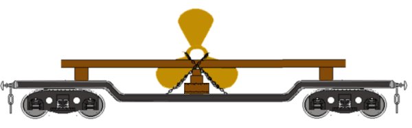
Model ships use items such as barrels, anchors and propellers which can be of interest, commercial examples of the former are generally a bit on the large side, and larger propellers required special wagons to carry them. Ships propellers were invented in 1836 and they came in a wide range of designs, the basic small coastal steamer would have a three or four bladed propeller roughly three foot in diameter, larger propellers would be rare. Propellers of less than eight foot diameter could be laid on a bed of bracken laid on a flat wagon and roped down, care would be required however as the blades might be damaged when lifting the thing on and off the wagon. Very large propellers might be carried on a wooden framework, built on a bogie well wagons (such as that offered by Fleetline), but always supporting the propeller under the centre boss, not with the blades resting on the floor of the wagon, or with anything (including securing chains) through the centre hole. Ships propellers of this sort of size would usually be four bladed however most model boat propellers are three bladed as shown.
Fig ___ Ships Propeller
Note that on wagons fitted with longitudinal baulks, as shown above, these were not always placed either side of the load. I have seen photographs of large pieces of machinery being transported on such a wagon with both baulks on one side (one on top of the other) and chained together with the load resting at an angle against these and chained to them. I suspect that having dropped off the load the two baulks would have returned to their more usual position on the wagon. Also if you want removable loads having the two baulks with a gap between them makes life a lot easier.
Ships anchors are by their nature large and heavy, they are also expensive to cast so if one was lost the ship would try and retrieve it if at all possible. The long thin shafted 'admiralty' type anchor was associated with sailing vessels, steam and motor ships preferred the flat 'tripping-palm type. Again the sort of anchor one might see on the railway would typically be quite small, a tripping palm anchor for a small coaster might be four or five foot long with a base perhaps two foot to two foot six inches wide.
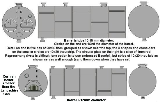
Industry ran on steam right into the 1970s and new boilers were a fairly regular 'large load', although they were actually not very heavy for their size. The most popular type was the lancashire boiler, with two fire tubes, as shown in the sketch below. Less common was the older 'Cornish' type with a single fore tube. These would have been transported on a flat bed wagon, drop centre for boilers larger than about seven feet in diameter. The boiler would be chocked in position with timber, often this was cut into wedge shapes but sometimes a few railway sleepers would be used to build a cradle. The boiler would be chained down with heavy chains over the top and secured to the wagon.
Fig ___ Lancashire and Cornish boilers
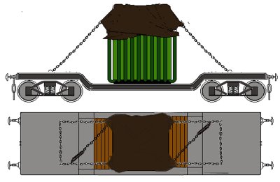
Large electrical transformers (a block of wood or length of square section Plastruct or copper tubing with the cooling oil pipes on the sides from wire) were often carried on specially built transformer wagons which had a recessed floor to allow tall transformers to be carried. As transformers increased in size and began to exceed the loading gauge prior to the second world war most of these wagons were converted to other uses. Standard wagons were also used, the sketch below shows a medium sized transformer loaded onto a bogie well wagon. The method of securing seems to have been fairly standard, a long chain is attached to one of the lifting lugs on the transformer, taken down through a securing loop on the wagon, then across to the other side, up and through the other lifting lug, then back across to the other side where a turnbuckle is used to tighten it. The securing rings used on the wagon could be as shown or they could be in the well itself, which means by adding lengths of stiff wire to the base of the transformer, with the chains secured to the ends, the load can be made removable. Not all such loads were sheeted but it does make modelling the thing easier.
Fig ___ Large transformer load
During the war the introduction of triple-bladed propellers for aircraft produced some interesting stock modifications. The aero propellers themselves were shipped in Y shaped wooden cases, with the single stem down. They were loaded two to a wagon, supported on simple wooden trestles with the Y lying fore and aft, the downward pointing end passing through a hole in the floor. Because the downward part of the Y extended through the floor the load was off-centre toward one end of the wagon so that it did not foul the brake gear. The GWR used converted flat wagons for these propeller cases, you can knock a couple of these up using the Peco single bolster pair. The LMS used 5 plank `Medium' goods opens similarly modified. I made up some inserts for 5 plank wagons to represent these, this proved to be quite simple using a floor of 10 thou card, crates made up from scribed card and a supporting frame made from 30 thou square rod and 10x20 thou strip.
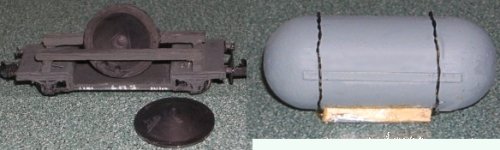
Do keep an eye open for parts to go in your bits box, the 'ends of a retort' shown below left are the pull-out inserts from cartons of orange juice (the wagon was a 'quickie' for a youngsters layout, made about twenty years ago and not up to my normal not very high standard). Large objects should be chained down and a circular reto9rt ends would also be chocked in position with timber, match sticks glued to a base (baco-foil folded in half and super-glued) would make a removable set of chocks and twisted wire chains bent to shape would allow these to be removed. The 'gas pressure vessel' was made from the ends of Safeway sweetener dispensers (sadly no longer in production) which serves as a removable load for a Fleetline bogie well wagon. The tank sits on cut down match sticks with twisted wire chains glued to the tank.