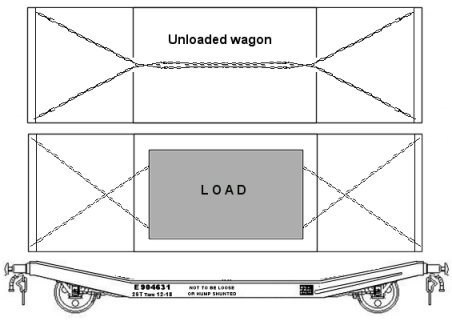
Road vehicles and farm equipment was moved on a wide range of flat bed stock including specialised crop-centred vehicles such as the 'lowmac' or low machinery wagon. These were equipped with securing rings, some had chains permanently attached and these were typically connected together when not in use as shown in the upper sketch below. When being used it seems to have been standard practice (where practical) to cross these chains at each end, as shown in the sketch below.
Fig___ Chains used on a lowmac wagon
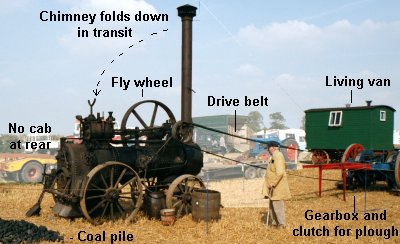
One regular cargo would have been 'portable engines', these were originally small steam engies on wheels that could be towed about the place and used to power industrial or agricultural equipment. These are in effect simply a boiler mounted on wheels and equipped with a piston mounted on the top toward the rear powering a drive wheel from which belt drive was used to power equipment. These engines could be towed about to be used as required, they were quite commonly used by farmers for driving threshing machines and the like and were very common in quarries where they powered the stone crushers (see Volume 2, Quarries). These portable engines remained in fairly widespread use up to the Second World War but disappeared rapidly thereafter. A visit to a `Steam Fair' may be worthwhile to see the real thing and check on the colours used.
Fig___ Portable engine as used on a farm or factory
A model of one of these may at some point be available from Lytchett Manor Models (link on the links page - This company now own the former Fleetline and Skytrex molds).
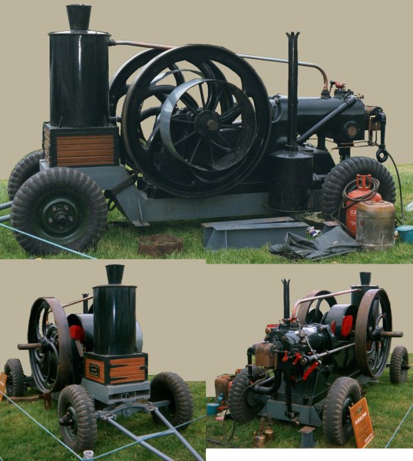
By the time of the First World War there were increasing numbers of internal combustion engines being used in this way. S,all examples would be shipped in a crate, larger machines were on wheeled chassis, so they could be towed about, and would travel on a flat bed wagon or 'machinery truck'. The example shown below was used on a farm and only retired in the 1970s. This has two flywheels, one either side, and a single power take off drum on one side only (the smaller, slightly wider, wheel visible in the upper photo).
Portable 'oil engine' (Allan Oil Engine) on towed chassis
This is a rather complicated example, selected as it would make a more interesting model, there were much simpler units which would be easier to model.
Army Traffic
Up to the mid nineteenth century the British Army owned very few road vehicles, they were expected to hire or requisition vehicles locally as required. This approach meant that during strategic withdrawals the wounded and the women and children who accompanied the forces often had to be left behind. The war in the Crimea was the first to be regularly reported in Britain and the terrible conditions experienced in the winter of 1884-85 caused much debate amongst the British public. Enquiries were held and it was found that although food and equipment had been available they could not be moved up to the troops because of a lack of transport. After this war the army began to build and buy its own horse drawn waggons and carts. Most were four wheeled types and after about 1888 the design of the most common 'General Service' or GS type was pretty well standardised. The last of these army standard GS waggons were retired in about 1944.
The army waggons used the 'artillery' type wheels (you don't need to worry about that in N scale) and the body was supported above both the front and rear axles. There was a pole under the wagon joining the rear axle with the turntable for the front axle. These waggons were unusual in having a sprung seat (most civilian waggons had no springs for the seat). There was a tall brake lever to the right of the driving seat and a screw brake handle fitted on the right hand side at the rear. The army opted for a central pole and pair of horses rather than using shafts. When being carried on railway wagons the pole was carried under the waggon. The GS waggon was about thirteen foot six inches long, the overall width was just over six foot but the width of the cargo bay was only just over three feet. There were two raised 'raves' running along above the solid wagon sides. The height to the top of the back of the drivers seat was about seven feet, bringing the waggon comfortably inside the restricted British loading gauge.
Fig___ Army GS Waggon
Civilian Horse Drawn Vehicles
Horse drawn road vehicles and farm equipment are available from various manufacturers. Note the farmers waggons were built by local craftsmen to local designs and were seldom moved about the country. Railways used horse drawn vehicles and these would have been delivered by rail to an outlying station.
One point to note is that spoked wooden wheels are designed for strength in compression, tying a wagon down with ropes to the wheels would quite likely damage the wheel, always secure them with ropes to the axles.
Specialist road vehicles would be more likely to be shipped by rail, examples would include horse drawn tank wagons and some municipal service vehicles, a personal favourite being the 'gully flushing wagon'. The gully flushing wagon is a simple rectangular tank with some interesting looking lever arrangements on top. Being flat sided this lends itself to using printed paper sides to add the livery (probably dark green with the 'corporation' logo and name). The horse drawn tank wagon can be made using the tank from a Dornaplas tanker kit with P D Marsh wooden wheels on a microstrip chassis and with a cab from card.
Large furniture vans or 'pantechnicons' were carried on low-floored railway wagons and modelling these is discussed in the section on Kit Bashing. Some lines used standard height wagons for this traffic and the wheels had to be removed from the van, which was then lifted onto the wagon with the yard crane. Most companies built drop-centre wagons however, usually with smaller than normal wheels, to carry these vans. The vans could be seen singly or sometimes two or three would travel together, usually all from the same firm but not necessarily all of the same design.
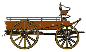
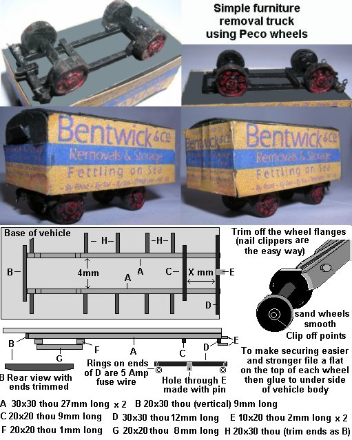
Horse drawn furniture vans are not too difficult to model, a simple option is to use Peco railway wagon wheelsets, suitable for heavier vehicles such as these. Many had large rear wheels mounted on a cranked axle but my furniture van is based on a photo of a van operating in London in the early 1930s. The body of the model is an upside-down cut-down Farish container with printed paper sides glued on and a simple chassis of plastic strip glued to the bottom of the vehicle. The body is 32mm long and the sides are 12mm high, with an additional 2mm for the roof the overall height is 18mm. The model was made many years ago and has spent years being handled by youngsters and stored in a damp shed, however the sides, although no longer glued down properly, remain in place. The printer used was an old 300dpi inkjet type, hence the 'speckled appearance of the sides, the paper was glued to the body by soaking it in Mekpak solvent.
Fig___ Simple furniture removals van
When in transit there would be the pole for the horses (a 20mm length of 30x30 thou strip) would be on the floor under the vehicle, this would be attached to the turntable at 'E' in the drawing using a heavy metal pin. The same chassis and wheels would serve for a heavy flat-bed waggon, simply replace the van body with a sheet of 1mm scribed card (the same length as the chassis) with a rail of 10x20 thou round the edges. The side pieces (H in the drawing) are rather more visible and important for a flat bed waggon. For a flat bed I would probably now use the Peco spoked wheelsets (not available when my van was built), I added black 'dots' to my wheels to suggest spokes.
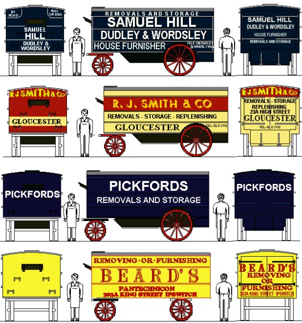
The sketches below show a selection of liveries, all based on either photographs or on advertising literature, the colours used are not certain but the relative shades are about right.
Fig___ Liveries for furniture removals vans
Steam Road Vehicles
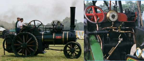
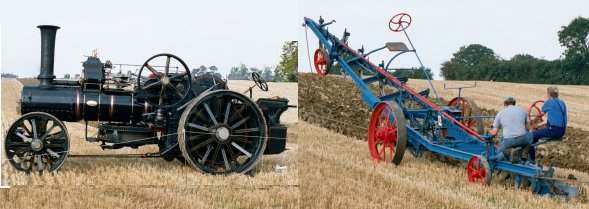
Steam road vehicles usually travelled by road, only occasionally being moved by rail (when they were urgently required). To keep within the loading gauge steam road vehicles such as traction engines would have their chimney removed (they are fitted with a hinge to allow them to swing down forwards but when I asked at a steam ploughing contest I was told removal would be more likely). Portable engines and steam heating boilers (discussed below) have a tall chimney that folds down to the rear for transport. The wheels would be chocked with heavy timber baulks and their design means they can be used to chain the wagons down although I believe the chains were usually attached to the axles. The photos below, taken at a local steam engine rally, show a typical traction engine and the inset shows the controls.
Fig___ Steam traction engine
Road-Rail Tank Wagons
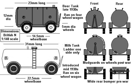
One item worthy of mention was the road trailer tanks carried on a special flat wagon similar to those used for moving machinery (although these usually had level decks rather than the dropped centre section of the machinery wagons). Road tank trailers carried on railway wagons were used from the mid 1930's for milk and beer traffic, the only problem is that the liveries would be difficult to produce. If using the Ratio oil tank as the basis of a model, upside down so the walkways and filling caps are at the bottom, one option would be a pre-printed wrapper glued to the tank body. The ratio tank has a 25mm central section, the domed ends bring the length to 28mm, falling between the correct length for eaither of the tanks shown below (although close enough for the milk tanker). One small point - the Ratio kit comes with two hand wheels per tank, which serve well for the handwheels at either end of the milk tank. Pneumatic road wheels are available separately from some of the white metal kit manufacturers and in the Dornaplas plastic range. At a pinch the Peco wagon wheel sets can be used as described for the furniture removals van above, however as the are rather more visible on a tank wagon a fair bit of filing down of the inner faces would be required. Very early milk tank trailers had six spoked wheels, four at the back and two at the front. These are hard to find but one option is to use Peco spoked wheelsets with the flanges trimmed off and the tyres sanded smooth (sanding the inner faces helps s this reduces the width of the wheel). Another option is to use the road wheels from a 1:72 World War Two German tank of the Pz III type (although these are a bit on the big side).
Fig___ Beer and milk road rail tank trailers
Most of these tanks were conventional trailer types with four wheels as shown but in the late 1930's a few were built for use with articulated tractor unit. These trailers had two wheels at the rear and a supporting strut with small wheels at the front which folded up and back as the tractor reversed into position to couple-up.
The railway wagons used for road tank trailers were of various designs, the smaller tanks were moved on a ten foot wheelbase four wheeled chassis, the milk tanks travelled on six wheel chassis, typically a 12 foot over all wheel base (both are described in the section on Kit Bashing).
Motor Vehicles and Caravans
See also Freight Operations - Non Passenger Coaching Stock - Private Carriages and Motor Cars
Putting the right type of motor car on ones car carriers is a good move, even simple detailing with a lick of paint and adding windscreens makes a big difference. Model aircraft suppliers may stock something called `Krystal Klear' (used for airliner windows), a PVA based thin paste which is stretched across the window opening with a cocktail stick and dries clear.
Motor cars were carried in railway company Covered Carriage Truck vans and on purpose built four wheeled 'open carriage truck' wagons. The motor car wagons or 'open carriage trucks' were equipped with transverse bars but the vehicles were actually secured by wrapping straps or chains covered in thick rubber hose round the axles. On car carriers these straps or chains were usually attached to adjustable mountings on the wagon sides (not to the transverse bars). On wagons designed for farm implements and the like heavy iron rings were provided for securing the load, either mounted along the outer edges of the floor or on the sides of the chassis. In both cases the straps or chains remained attached to the wagon when it was unloaded so they need adding to an empty wagon.
As car production increased one common vehicle was the 'carflat', a redundant railway carriage chassis fitted with a simple wooden floor and securing points. These would travel in groups from the manufacturers to a local distribution point, similar vehicles were used for private motor cars attached to passenger trains such as those in the motorail services of BR.
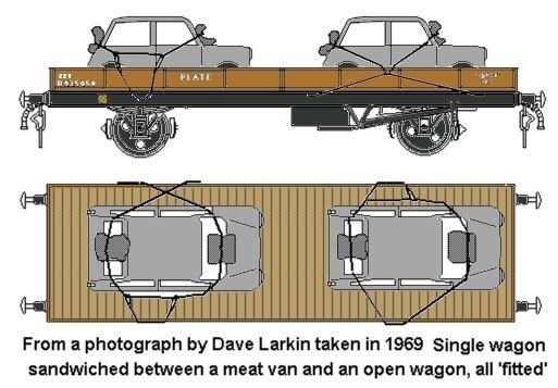
Remember that road vehicles were also moved about on flat wagons or plate wagons, usually 'fitted' types. These did not have the special securing straps or chains so the cars were roped down. On cars built after the 1950s there was no chassis as such, so the vehicles were secured ropes passed over the body and with large cushions under the ropes to protect the paint work. There is a picture of two mini's loaded on a Peco type plate wagon in Dave Larkin's book 'Standard BR Freight Wagons' (D Bradford Barton, published in the mid 1970's, see Bibliography), and in his companion book pre-Nationalisation Wagons on British Railways' is a picture of a flat-fronted Ford van chassis and cab loaded on a similar ex-LNER wagon. More recently I have seen a photo of a single car secured in this way in a lofit (1 plank) wagon but in general these loads were unusual, by the later 1960's transporting road vehicles in this way was the exception rather than the rule and usually only occurred when the delivery drivers went on strike.
Fig___ Minis on a plate wagon
There are several ranges of white metal cast vehicles, although many of these have solid windows which does detract from their appearance. The Scalelink range is generally considered to be the best available, although at the higher priced end of the scale. Some research may be required to select a suitable prototype for the era being portrayed. For more modern layouts the Ibertren range included a packet of small (Seat/Fiat) family cars of a typical modern saloon type that could be used to replace the rather distinctive Merc's on the Lima articulated carrier.
Something seldom modelled as a wagon load is the motor-caravan (a caravan designed to be towed by a car rather than a horse), by the mid 1930s these had become quite popular, although they were at that time built by 'coach builders' as one-offs rather than mass produced. A single caravan might be shipped by rail rather than towing it all the way from (say) Bristol to Scotland for a touring holiday. It was not uncommon to ship the car as well, with the family taking the train. The 1930s caravans were wooden (often using the new 'wonder material' Plywood for the outer skin), with a waterproofed canvass roof (as used on railway vans), for illustrations of the type see 'Appendix One - Road Traffic - Tramps Camping and Caravans'.
By the early 1950s mass produced caravans, using an aluminium skin, were on the market and a consignment of caravans being shipped to a distributor makes an interesting load. Such traffic was certainly seen from the later 1950s on and may have been seen in the immediate pre-war era. These were (typically) collected from the makers by a three wheeler Scammel tractor (towing them on their own wheels for a short run or carrying one on a flat bed trailer for a longer trip to the station) and anything from one to five vans might be shipped at one time. The photographs I have seen suggest that lowmac wagon were favoured for this traffic although smaller vans would fit on a one plank wagon or similar. A single van would probably be loaded onto a drop-side wagon at a loading bank, subject to its height of course, end-loading wagons might use an end loading dock but where more than one van was moved larger yards used their heavy fork lift truck to lift them onto the wagon from the side. This load offers you the option of running multiple lowmacs, something you do not often get to do.
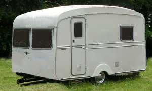
By the mid 1950s the caravan was recognisable as the modern general design, a slab-sided box with a slight curve on the front and rear of the roof running on two small wheels and with a 'ball hitch' tow bar on the front.
Typical mid 1950s caravan
Note that the caravan would not be secured with ropes around the body, it would be held in position with rope or chain attached to the chassis (although there might be a rope or two over the roof to help keep it upright).
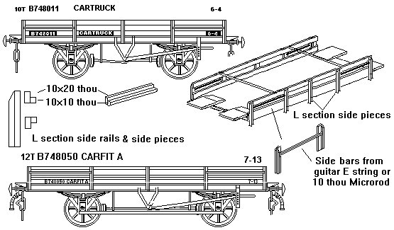
Cars for export
Cars were exported via the train ferries in some numbers during the 1930's and following the Second World War this traffic continued (mainly handling Morris cars I believe). Specially built 'ferry' open carriage trucks were provided for the traffic by the Southern Railway and later by BR. Other than the ferry fittings these open trucks resembled the standard carriage trucks of the day. BR built some longer wagons for this traffic (the 12 foot wheelbase Carfit C) but these found little use and I believe they were transferred to the engineers for use as runners or general purpose wagons in the later 1960's.
Fig___ Cartruck and Carfit C wagons
Motor cars going to the docks could be a 'one off' shipped by an individual or from the late 30's in larger numbers for export (these were carried on temporary decks built into the ships holds). In either case they were usually off-loaded at the docks using two metal channel sections rested up against the end of the wagon. They were lifted onto the ship using either two long nets perhaps three feet (1 m) wide under the wheels or bars slung under the axles. Either lift would be suspended from cross bars so the cables did not bite into the body and these crossbars were then slung from a spreader bar, the lifting point being the centre of the spreader.
A common practice when sending a car by sea was to put it into a wooden box or container, an example of this may be seen stowed on the Robin in St Katherine Dock in London. There were snags with this system, for one thing unseasoned wood used for the case often caused corrosion due to condensation.
Alternatively they might be shipped as CKD (Cars Knocked Down). CKD consisted of sets of chassis nested together, sets of bodies or cabs similarly nested together, the engines in crates, interior fittings in cases and the wheels fastened together with a bolt through the hubs and a nut on each end. The wheels were shipped with the tyres on. CKD was standard practice for exporting commercial vehicles by sea up to the 1960's. Extra tyres were shipped loose, or threaded onto ropes in fours and on the ships they were simply piled in wherever they would fit.
Motor lorries and other commercial vehicles
Motor lorries and other outsize vehicles would sit too high and foul the loading gauge when loaded onto standard height wagons. There is a photograph of a Bedford lorry loaded onto a bogie well wagon in Dave Larkin's book on Standard BR Freight Wagons, the lorry is parked with its front wheels in the well and its rear wheels on one raised end, this brought the roof of the cab down to within the loading gauge and kept the engine and hence the centre of gravity close to the centre of the wagon. BR inherited quite a few 'lowmac' low-centred machinery wagons, they even built some themselves, and in the 1970's they converted some older Freightliner container flat wagons for carrying larger road vehicles. The N Gauge Society offers a nice kit of the Lomac, Graham Farish offer the Freightliner wagons and Lytchett Manor Models (link on the links page - This company now own the former Fleetline and Skytrex molds) may now offer the Lowmac and bogie well wagon as whitemetal kits (details of kit-based home made versions of the Lowmac and drop-centred trolley wagons can be found in the section on kit bashing).
Road trailers, of all types, were an occasional cargo for the railways, quite a lot being for their own use. These would travel on anything of suitable length, plate wagons were used as well as the longer car carrying wagons (four and six wheeled types). Trailers are easier to model than lorries and this represents a low-cost option for wagon loads. The Dornaplas road wheels can be used for trailers dating from the mid 1930s on, the body can be made up from plastic card and the drop-leg at the front of articulated trailers can be produced from scraps (there is a sketch showing this part for a BR owned semi-trailer in the section on 'Unit Loads - Early container types'). Van bodied trailers would need to be moved on a Lowmac or similar drop-centre vehicle. The trailer would be secured to the wagon with ropes or chains attached to the chassis.
In the mid 1980's a single decked version of the six wheeled articulated Autic Six wagon appeared. Owned by MAT these were known as Comtics and they were used for lorry traffic, notably exports of cab and chassis units from Leyland Daf in Lancashire. These wagons can be made by cutting the upper deck from a Lima articulated car carrier, in the pictures I have seen they carried three lorries, one in each dropped bay and a third loaded over the joint in the centre (handy as this hides the hinge on the model). The Dornaplas Ford Cargo lorry would look the part, and you get to buy the cheapest un-bodied version.
Farm Vehicles and Equipment
Farm machinery and tractors were regular rail cargo from the 1830's up to the mid 1960's. Prior to World War Two, if the firm had no dedicated siding, horse drawn vehicles and motor vehicles were taken to the goods yard under their own steam, equipment such as a plough or roller being carried on a trailer (probably owned by the railway but possibly by the makers or a local carter). By the 1950s all types of agricultural vehicle were usually taken to the railway yard on a flat bed trailer, generaly towed by a British Railways three wheeler 'mechanical horse'.
Note that vehicles would be secured to the wagon with rope or chain attached to the chassis, a tall item, such as a 'forage havester' (a tall rectangular box with a 'lawn mower' at the base, used to cut grass and blow it into a trailer) would have ropes (not chains) passed around the body to help keep it upright.
Lincoln is famous for agricultural machinery and Gainsborough and Grantham are also centres. Contemporary accounts suggest that early factory made farm equipment (ploughs harrows and the like) were painted a light blue colour.
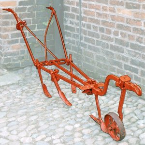
Ploughs, at least the horse drawn type, are actually rather small, it would be unlikely to consitiute a wagon load on its own, although on a branck line it might do so. The example shown below is actually a harrow not a plough, but it serves to give some idea of the scale of these earth-cutting horse drawn implements. In operation, with the blades in the drond, the man standing at the rear would be bent forward slightly to keep his hands on the handles.
Fig___ Typical horse drawn harrow
The Dutch invented the steam powered ploughing engine (which drags a plough across the field using ropes) and this found favour in Britain in the mid 19th century. W&T produce a set of Fowler ploughing engines (which often operated in pairs) with a 'cultivator'. These are pleasing models although you need a deck 18mm wide to accomodate them (slightly wider than the standard Peco wagon deck, this is more fully discussed in the section on Kit Bashing). These engines usually travelled by road, towing a living van or trailing the implements they used, however when new they might well be delivered by rail. To go with the Flowlers you could build a 'balance plough', these were double ended things designed to be pulled one way across the field, tilted over and pulled back again. This would take a fair bit of modelling but would make an impressive load, one point to note is that the wheel on one side is perhaps a foot shorter than the one on the other side, in use the big wheel ran in a furrow with the smaller one on the un-ploughed side. The engine shown below is a Fowler, there were other makes.
Fig___ Typical steam ploughing engine and ballance plough
For larger ploughs (with perhaps seven blades on each end) two ploughing engines were used, one on each side of the field, in transit on the roads one engine towed the plough the other pulled the living van. When smaller ploughs were used a single engine was often used with a heavy earth anchor on the far side of the field. Sadly, to date, I have not been able to trace a decent photograph of the 'anchor' as this would also form a handy wagon load. The ballance plough was not always such a big piece of kit, the example shown below works with a 'portable engine' using pulleys on small earth anchors (visible bottom left). This plough was being used with the portable engine shown above.
Fig___ Small two furrow ballance plough
These ploughs continued in regular use, although hauled by tractors rather than steam ploughing engines, into the 1960's.
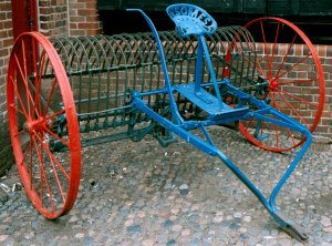
When looking at preserved gear it is worth giving what you are looking at a little thought, for example the vintage Ransomes rake shown below was oringinally a horse drawn implement but the shafts have been removed an bent metal rods added so it can be used with a standard petrol tractor. In a layout set from the 1930s to the 1950s such an item might well have moved as part of a farm removal job. This is actually not that difficult to model, I made one many years ago using the spring from a ball-point pen sandwiched betwen two lengths of brass wire and soldered, with additional detail added from wire and plastic strip glued in place.
Fig___ Old farm rake modified for use with a tractor
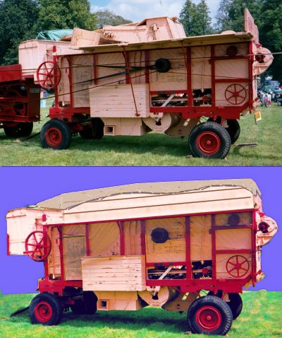
Threshing machines were invented in the late 18th century and by the 1850's these were driven by steam engines. These machines resembled high-sided wooden carts with a wheel mounted on the side to take the drive belt. By the 1950's these machines had improved to the point where they threshed and winnowed the grain and poured it into sacks. The photo below top was taken at a show in 2002 where a threshing machine was set up to operate. When in transit the platforms at the upper sides would be folded up and all belts would be removed as shown in the lower illustration.
Fig___ Threshing machine in use at a show in 2002
An older threshing machine is available from XXX and a mobile steam engine to drive it from XXX.
The first petrol powered farm tractor was built in America in 1892, the first British farm tractor was the three-wheeler Ivel of 1903 (developed by a bicycle maker in Birmingham). By the time of the First World War there were quite a few tractors on the market but farmers being a conservative bunch there were few at work in the fields. Horses and oxen were still in widespread use but the demands of war left the farms short of both labourers and horses and the Government asked the Americans for assistance. The tractors which arrived from America were mainly built by International Tractor. These machines would look familiar today, they have the standard arrangement of two larger wheels at the rear with two smaller wheels in line with these at the front, but the rear wheels were plain metal with diagonal ribs across the flat steel 'tyre'.
At the time a lot of farm equipment such as threshing machines and the like was driven by belts, usually from a steam traction engine or portable (tow-able) steam engine. The petrol tractors had flywheel like arrangements to either side of the bonnet to drive the belts on this kind of equipment.
The hard times of the 1930's left many farms bankrupt and delayed investment in tractors. By the time of the Second World War much farmland was idle but the farmers lacked the men and resources to plough it under for crops. Again the Americans helped by sending tractors, the most common type this time as built by Fords, who's commercial vehicles were called Fordsons. At the time there were a lot of three wheeled tractors in use and some of the American machines had the two front wheels mounted close together, giving effectively a three wheeler arrangement. Throughout the war horses and oxen remained in common use on the land and equipment such as ploughs which had been designed for horse haulage or steam engine towing remained in use.
After the war the USA supplied many older re-conditioned tractors as part of the Marshall Plan and in the 1950's when exports were so important there were photographs taken of farm tractors loaded onto individual 'Lowfit' steel wagons on their way to the docks. A kit of a 'period' tractor which would serve for the American type and a similar kit of a 'modern' tractor which would serve well for the 1950s exports may now be available from Lytchett Manor Models (link on the links page - This company now own the former Fleetline and Skytrex molds).
Ferguson tractors are grey, Massey-Harris or the later Massey-Ferguson tractors are red, Fordson (the commercial wing of Ford) tractors were grey until 1932 when production moved from Cork in Southern Ireland to Dagenham and they changed to a dark blue (similar in shade to the Graham Farish LNER sand wagon) with light grey exhausts.
Langley offer both modern and period (1940's-1960's) tractors and use these to offer a ground preparation scene and a harvesting scene with additional models of farm equipment.
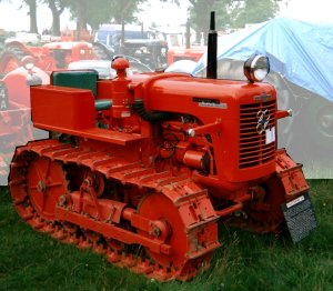
The 'caterpillar' tractor appeared in 1931 but they were little used in Britian. One example is shown in the sketch below, a machine intended for tilling the ground at sugar plantations in tropical countries it was first built in 1935. Small numbers of these machines would have been shipped to the docks by rail, probably in one's two's or three's.
During the Second World War the military made use of small crawler tractors in a number of ways, many of these were then sold to farmers after the war. I wasn't able to find an ex-military type to photograph but the Platyphn 30 shown below is typical of the breed (photographed at a steam rally in 2002)
Fig___ Platyphn 30 - post war crawler tractor
There are photographs of a smaller variant of this type of machine in Appendix One - Road Traffic - Introduction, Licensing, Wheels, Suspension, Brakes and Transmission
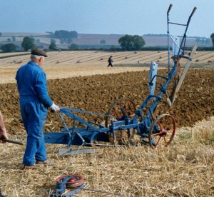
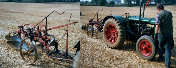
Returning to conventional tractors the adaption of equipment such as the plough from horse drawn to tractor hauled brough a range of problems, for one thing (if one man was to do the job as before) the controls had to be moved to the front and extended so the tractor driver could reach back and handle them. The result was that the plough was substantially different from the horse drawn type. Another point to note is that, up to the 1970s, tractors were by and large rather small by modern standards, the photos below show a pre-war plough and its associated tractor.
Fig___ Pre war tractor towed plough
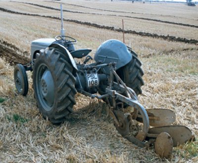
By the later 1930's early forms of 'hydraulic' rams were available, these actually used oil not water but the name has stuck. These early rams were little used in practice due to problems with the oil seals leaking and the difficulty in making flexible hoses of sufficient strength. Up to this point almost all tractors were painted red but shortly after the war Fergusons of Coventry introduced their revolutionary T series tractors which were painted grey. These had a hydraulically powered frame at the rear, called a three point linkage, and a rotating power take off point mounted under that. The Ferguson was designed to use specially built equipment fitted up to use the linkage and power coupling on the tractor. Ferguson provided a big range of equipment including ploughs, grass cutting shears, and powered muck spreaders. The Ferguson system meant that one man could both drive the tractor and operate the equipment and it revolutionised farming practice.
Fig___ The Ferguson with three-point linkage and one-man plough
By the 1970's Britain had the highest density of tractors and the highest number of tractors per head of population in the world. Oddly enough in France, an unquestionably industrialised country with a large agricultural sector, has the lowest proportion of tractors, but it does have the largest number of cows per head of population.
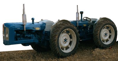
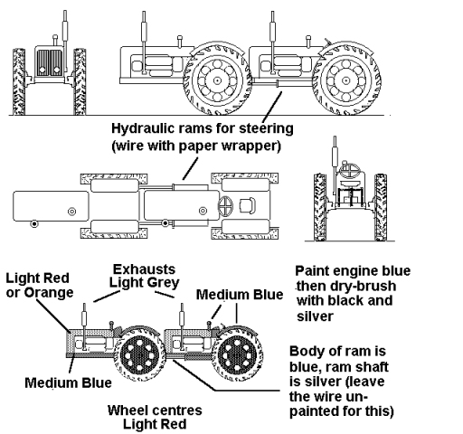
For something a little different you can take two 'modern period' tractors and build something called a Doe. This machine was developed by a farmer in Essex by the name of George Prior, he built a number of double-tractors and sold this, his final design, to Earnest Doe & Sons (agricultural engineers, of Ulting near Maldon in Essex). There was an article on these machines by Joe Hollin in the May 1998 edition of Old Glory magazine, complete with several photographs. They were built in the early 1960's and some remained in service when the article was published. The Does were built using a variety of Fordson tractor types, resulting in a range of colour schemes. The original models appear to have been all-blue, as per the standard Fordson livery, but the colour scheme shown is for an early machine which was still working in the late 1990's. Some later Doe's had the full cab but many were open as shown.
Fig ___ Photo of a Doe Tractor
The machine is driven from the rear tractor, there is no steering wheel on the front machine. You need to file away the rear of one tractor to leave a floor at the rear but no driving position. Super-glue the front end of the second tractor to the filed down rear of the first and add the hydraulic rams for steering from steel guitar wire with one end wrapped in paper. The link cable between the front and rear machines is best represented using a length of coiled guitar wire painted dark grey, ideally this should be about 30 thou (0.75mm) in diameter.
Fig ___ Modelling the Doe Tractor
The Doe was designed to provide the same pulling power as a crawler with the speed of a normal tractor for use where the ground was heavy clay. They were expensive (the cost of two tractors plus the conversion), so they were shipped as one-offs. This machine was quite low (just under eight foot to the top of the exhaust) so it does not need a low-loading wagon to carry it. The Peco 'Plate' wagon would do at a pinch but this would be quite close to its weight limit and a better option would be a short bogie wagon. There were still a number of old wagons in use in the 1960's so one option would be the Bachman 'Old Timer' flat wagon. The tractor would be secured using chocks under the wheels (scraps of match stick painted black) and would probably have chains passing over the axles and secured to the wagon.
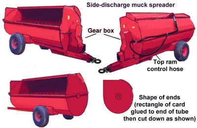
If you build a Doe you will have two sets of small road wheels free and these can be used for a range of farm implements built from the late 1940's onwards. The examples shown below were chosen because they are distinctly agricultural and not difficult to make. Both are designed for muck-spreading, the open trailer threw it out at the rear whilst the drum shaped trailer threw it out of the side, both are post-war as they rely on the power take of on the tractor to drive them (introduced with the revolutionary hydraulic 'three point linkage' on the Fergusen T series tractors in the 1940s). Either can be carried on a simple Lowfit or two might form a load for a Plate wagon.
The side-dischare type came in (I think) in the mid 1960s, possibly as late as 1970. There is a good photo of one roped to a lowfit wagon in the mid 1970s in Dave Larkin's BR Standard Wagons - A Pictorial Survey (Bradford and Barton 1979). This type is very easy to model, they were I believe always red (I could be wrong on that but I have only seen red ones). The body is a length of tube of 7-9mm diameter 20mm long with one quarter cut away, the cut away section is then opened out and glued to the outside, sand this down to represent the lifting top section (that allows top loading). The ends are rectangles of 10 or 20 thou card glued on then cut away to follow the line of the tube, leaving one corner where the opening is on the side. The side and end strips are 20x20 thou strip. The wheels can be any you have of about 8mm diameter, these can be attached to an axle, glued to the under side of the body then 'boxed in' with Milliput. The tow bar extends back as far as the axle, mounted on top of this is the gear box that drives the inner works, with a coupling to allow it to recieve power from the take off on the tractor. The ram controling the top section is wire with some paper wound round it, the hose to connect this to the tractor is black mono-filament fishing line. The inside is simple, a horizontal bar runs from front to back with chain (black thread) suspended from it, in use the chains spin on the bar and throw the muck out of the opening.
Fig ___ Post-war side-discharge muck spreader
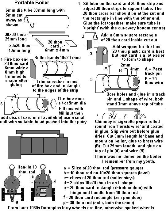
There are several kits of horse drawn wagons on the market all of which could serve as potential loads for wagons. The Langley range of whitemetal castings includes several farm implements which serve well on low flat wagons. Another farm related `road vehicle' moved by rail was the portable steam heating boiler, used to supply heating for greenhouses and the like. These resemble portable steam engine but lack the piston and flywheel on top so they are very easy to make using Plastruct tube (boiler and chimney (folded down along the top in transit), plastic strip and either Langley spoked or Dornaplas tyred wheels, you could even use Peco wagon wheels with the flanges cut off as these boilers often had wide tyres for use on muddy ground).
Fig___ Portable heating boiler for greenhouses
Construction Equipment
Up to the 1950s or early 1960s construction equipment was a regular rail cargo, for more on the sort of equipment involved see also Appendix One - Roads and Roadworks for examples of these vehicles and equipment.
Caterpillar tracked vehicles would make interesting loads for a drop-centred wagon such as the bogie well wagon and larger 4-wheel drop-centre trolley wagons. Caterpillar tracked vehicles date back to the time of the First World War, quite a few steam excavators and the like ran of a catepillar tracked chassis. Small 'crawler' tractors appeared after the second world war (and disappeared by the late 1960's) and these could be moved on a four wheeled 'Lowmac' wagon.
Caterpillar tracked or 'Crawler' cranes and the like tend to have small road wheels (these are the wheels inside the loop of track), perhaps a foot or so in diameter, machines intended to tow things tended to have larger wheels or had a row of return rollers at the top so that they could climb taller obstacles. If anyone has access to 1/72nd Second World War kits there used to be a couple of kits which included a German half-track motor cycle the tracks from which would serve for a large diesel bulldozer or crawler towing type machine (post 1944 or so). For the tracks used on cranes and excavators the best bet is to cut a series of 2mm lengths from some 2mm diameter plastic tube, you need about ten per side. Lay these on their side on glass or a tile using a steel edge to line them up so they just touch and add a little glue to the joints. This gives you the wheels, add a strip of 40x40 thou (1mm square section) to the row, secured about on the centre line. Now cut two rectangles of 40 thou each 16mm by 20mm and glue these together to form the base of the machine. The strips on the wheelsets can now be glued to the underside of the rectangle. Paper strip 2mm wide can be used to represent the tracks, paint this light grey and add black lines with a fine pen at 1mm intervals to represent the gaps between the plates. When dry wrap the strip carefully round the wheels with the join on the under side and fix.
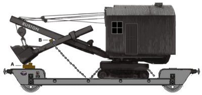
Langley now offer a crawler excavator kit in their white metal range. This is technically a post world war two machine but would serve for pre-war layouts as the basic design dates to the 1930's. One option is to use the jib and bucket and possibly the caterpillar tracks but add a new cab and engine housing from half of a Peco four wheeled refrigerated van kit body. This would produce something akin to the earlier steam powered excavators although most of those were mounted on railway wheels and ran on tracks in the working area. Both the steam and diesel types were loaded on heavy drop-centre wagons, being on tracks they could be loaded via the side. The four wheel trolley wagon shown can be modelled using a Peco 10 foot wheelbase chassis, a shorter version is described in the section on 'Kit Bashing'.
Fig ___ Crawler excavator.
Note the bucket is supported on a pile of timber baulks in transit (A) to protect both the bucket and the wagon and a timber baulk is used for the chains holding the jib steady (B). Cut-down match sticks, sanded down and soaked with black ink would do for this, they can be glued into a pile with PVA and secured to the model with super glue. The body of the vehicle was often green, the roof was usually black as was the chassis. I havle also seen pictures showing a large pile of sleepers built up under the jib, however that would require a lot more work and the example shown is based on a photograph.