Bulk minerals were the staple traffic for most of the railway companies and these were handled in much the same way by most industries. A surprising amount of loading and unloading was done by hand using shovels and wheelbarrows. Minerals such as coal, iron ore and broken stone were all commonly loaded onto railway wagons from hoppers or silos, usually mounted over the tracks but occasionally feeding out to the side through angled chutes. In the early days these storage bunkers were often supported on heavy timber trestles or solid stone or brick-built piers.
After about the 1880s steel rolling technology allowed the making of heavy steel girders, H section is used for verticals supporting I section transverse members. This allowed people to build sky-scraper buildings but on a more mundane level from the turn of the century many large hopper installations used steel supporting sections. As most minerals were sold by the wagon load, and most wagons were rather small, many mineral hoppers were not very big. Some even today are little more than a funnel to allow lorries to tip directly into the railway wagons.
One fairly common feature of the examples built since the 1950s is heavy rubber sheets hanging down over the railway loading bay, added to keep the dust from spreading quite so far. In practice the wagons tend to damage these rubber strips and a little careful cutting can give you a curtain which looks right but which does not quite touch the wagons passing below.
Note the Faller 'gravel silo' (2149) is not really suitable for a British layout, and I personally don't think it is a very convincing model for any layout, also their 'Loading silo' (2193) just isn't, it is a curious structure with a conveyor belt feeding directly into the base of a loader, there is no silo. This latter could be converted to something resembling a British prototype with a silo, there was an article in XXX Scale Trains magazine describing such a structure in XXX. The kit would need to be separated into two parts, the lower housing the discharge apparatus and control room, the upper housing the conveyor belt delivering the gravel. You would need a new conveyor belt as the one supplied would no longer reach, but this is no great loss as it looks rather heavy and unrealistic anyway. Between the upper and lower parts you then add a two inch length of tube and four lengths of Plastruct H section to support the upper section. The sides of the base would normally be enclosed on a British structure and the rubber strip curtains described above would be desirable. Having done all of this it might have been easier to build it from scratch.
Fig ___ Mineral hoppers
For a larger installation Kibri offer a 'gravel works with loading silo' (B-7482), this is about four inches wide by six inches deep and is designed to accept a single track under one end. With some care there are two inner bays, intended for road lorries, which could be opened up to allow two more railway tracks to be accommodated.
The obvious advantages of hopper type wagons which could be unloaded simply by opening the bottom were realised very early on. The chauldron wagons on the plate ways had bottom doors and the Liverpool and Manchester Railway of 1830 used chauldron type hoppers to carry coal from some of the mines. Hopper wagons were commonly used for iron and other ores but coal was generally carried in non-hopper wagon types, mainly due to the cost of the receiving facilities and the fact that most coal was shipped in relatively small quantities to local merchants who preferred to own their own wagons. Only in the North East, and particularly on the NER, did the hopper type coal wagon and its associated coal drop really flourish (see Fig ___).
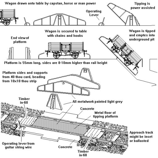
Unloading minerals from non hopper wagons can be done by hand with shovels, by crane using a grab, or by tipping the wagon. Coal merchants had to bag the stuff for sale, so hand unloading represented no additional cost, industrial users of coal and other minerals generally opted for tipping. End door wagons were built with tipping in mind, this involves a simple hinged section of track over the discharge pit. Early systems used a set of counter-weights to control the platform from about the 1940s hydraulic rams have become more common. One limitation to bear in mind if modelling an end-tipping scene is that the platform would never exceed an angle of about thirty degrees to avoid the wheel bearings being damaged. End door wagons were tipped into ships holds in western ports whilst ports on the east coast, notably in the North East, preferred hopper wagons which discharged from raised runways called staithes (see also Lineside Industries - Canals, docks, harbours and ship types). End tipping gear can be very simple, the sketch below is based on the installation at a china clay port in Cornwall, similar platforms were used at a number of industrial locations.
Fig ___ Tipper for end-door wagons
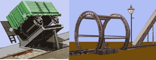
Wagons can be tipped sideways to empty them through the side doors, those with no doors at all can be turned upside down in a rotating cage or lifted and tipped over sideways. Wooden bodied wagons were tipped sideways from about the 1930s but as far as I am aware the rotary technique was only used with metal bodied types. Rotary systems usually involve a cage arrangement to hold the wagon by its top edge as it is tipped. The rotary tippler shown below is based on a tracing from a photograph and shows a rotary tippler in use before World War One. This was for standard mineral wagons of the time, although I would assume these would be grease axle box types as they are turned right upside down.
Fig ___ Side-door and Rotary Tippler
There was an article in the January 1977 Railway modeller magazine describing an 'O' gauge working model of a side-tipping installation complete with drawings and photographs of a prototype. The wagon is lifted through an arc of perhaps a hundred and sixty degrees and an ingenious weighted arm arrangement holds the wagon on the track as it is tipped. The article describes a fairly modern looking type which uses electric motors to rotate a quadrant shaped base. The wagons have to be uncoupled for side tipping but in some tippers a weigh-bridge was built-in, allowing the operator to do the clerical work of registering quantity delivered (the difference in weight before and after tipping) as well as the operating the machinery.
Modern stock such as the well known 'British Steel' 100 ton bogie tippler wagons were designed for rotary tipping and have special rotating coupling at one end so the rake can be emptied without uncoupling each wagon in turn. All three tippler systems, end, side and rotary, when used in industry were routinely housed in some form of building to offer protection from the weather and to reduce the amount of dust blowing about the area. For the end-tipping and rotary types the building need only be about one and a half inches wide in British N and the track runs through the centre line. With the side tipplers the structure needs to be nearer two inches wide and the track would be offset to one side, the other half of the building housed the tipping machinery and the receiving hopper.
Fig ___ Tippler arrangements
One point to note is that wagons with oil filled axle boxes have to have specially designed oil reservoirs for side and rotary tipping to stop the oil draining out.
Inside the factory or works the hopper-delivered or tipped minerals would be moved about either in small wagons, commonly two foot gauge edge rails systems, or on post World War Two layouts by conveyor belts. Conveyor systems are not a new idea, I have found references to their use in flour mills dating back to the 1790s, in Britain the first major application was in the manufacture of ships biscuits at the Royal Navy bakery at Deptford in 1804, by the 1870s this baker was producing biscuits on a fully automated production line.