Small mobile crane moving a container
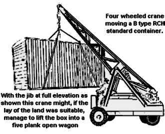
With the general increase in containerised traffic following the Second World War and the introduction of all-container trains such as the Condor London-Glasgow service additional cranes were needed and BR drafted in a number of mobile cranes, usually ex military vehicles mounted on lorry chassis. Those working in OO have the Airfix aircraft recovery crane, in N a bit of kit bashing is required. Fortunately there were many and varied designs used and the crane itself was of simple construction so fettling something on a commercial lorry chassis is not too difficult. (See Vol. 2 Fig ___).
One often sees photographs of RCH van type containers with the lifting chains and ring still lying on the roof which illustrates the main problem with this approach. The lifting rings on a van type container sitting on a railway wagon are something over eleven feet up in the air, even on the ground they are over eight feet up and a man had to attach the lifting chains to the container for the lift and then recover them afterwards. This was acceptable where traffic density was low and only occasional container had to be dealt with, there were plenty of other loads (machinery etc.) that required this kind of labour intensive handling and railway yards were traditionally well staffed.
The British initially saw the fork lift truck as the basis for a handy small mobile crane ( palletisation took a while to catch on in Britain) and even today there are many crane type variants of the basic fork lift idea. As a result they are more correctly called mast lift trucks, although they are usually referred to as fork lift unless the distinction is important for a particular job. BR used some of the larger early fork-lift type machines fitted with a frame from which four chains were suspended to lift containers on and off railway wagons and delivery lorries (semi-trailers were favoured for this work as the trailer could be left to be unloaded whilst the tractor unit returned for another load).
Fig___ Mast lift truck adapted for handling RCH containers
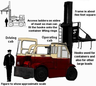
The example shown was sketched from a photograph on Paul Bartlet's website (see App 7 Useful Links), the photograph was taken in about 1961.
Further research revealed that this particular machine was a 1957 Shelvoke and Drewry Ltd. (Letchworth, Herts, England) 'Freightlifter' Heavy Duty Fork Lift Truck, Model 100 Dualdrive version. The example sketched as a top-lift frame attached (as well as containers the top-lift gear was used for timber, steel sections, pipes etc.). When heavy loads were moved (such as heavy girders) two of these machines could be used working together. It could be driven like a normal truck between sites at 22 m.p.h. and then controlled from the separate operating cabin. It was developed after the magistrates, at Slough, convicted British Railways for using a vehicle on the road in which the driver's vision was obscured by a 'jungle of steel'. The earlier design (which remained in widespread use in industry) had no cab as such, the operator sat in a centrally mounted seat underneath the two curved bars. This example could lift 18,000 lbs and carries special container lifting equipment. Principal dimensions: over-all height; fork raised 28 ft. (8.5 m.), Capacity: 18,000 lb. (8,164 kg.) at 33 in. (83 cm.). Engine: Diesel 65 bhp. or petrol 70 bhp. Outside turning radius: 16 ft. 11 in. (5.2. m.).
I had thought it was a re-hydraulic design, however Brian Carpenter was able to advise otherwise - The SD Freighlifter was most definitely hydraulically operated. It was based on an American Hyster fork lift truck, which import restrictions made it unavailable in the U.K. As an apprentice at S&D from 1953 I saw, for example, the main lift cylinder being machined, and S&D also made the control valves. As the refuse collection vehicles had coach built cabs the main cab on the Freightlifter was also coach built and had to fit under the tilt cylinder so was a very peculiar shape. The road driving cab was of all steel construction. There is an excellent book Kaleidoscope of Shelvoke &Drewry (published in 1980 and unfortunately now out of print) which has a black &white photo of a dualdrive. Also you probably know Bill Aldridge's British Railways Road Vehicles 1948-68 in the Nostalgia Road series which is still available, and has two or three Freightlifter photos. . Brian has a website devoted to these vehicles at - http://www.shelvoke-drewry.co.uk/ which is well worth a visit.
In the late 1950's a new approach was tried, known as the grappler arm lift. On this system the container has special lifting points mounted on the sides of the floor, they were usually simple inverted L shaped metal castings although on some designs there was a recess instead. The handling gear consisted of a rectangular frame with four arms dropped down from it, each with a small foot at the base that would engage with the corresponding lifting point on the container. The system was already well understood as this was how 'coach-built' passenger coach bodies had been lifted onto their chassis for many years. Again hydraulics were not yet reliable and I believe a simple arrangement of cable operation was used. In the sketch below the cable A is used to position the lifting frame over the container, then the strain is taken up by cable B. The strain on cable B pulls the grappler arms into place against the base of the container for the lift.
Fig___ Grappler lift points for N Gauge and principle of operation.
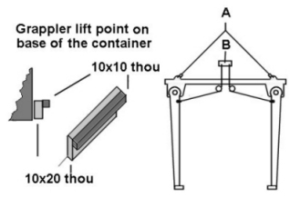
This required the containers to be built with the lifting points on their lower sides but the lifting frame could be used with any crane capable of handling the two-cable lift. Where a travelling gantry crane was used this was fine, where a fixed gantry was used however the grappler arms had to be swung out of the way as the frame was manoeuvred over the container. Usually they swung inwards, the mountings were at an angle so one pair swung inwards slightly and the other pair outwards to lie alongside each other (grappler arms are still in use today, usually attached to a standard ISO container lifting frame, and these swing out of the way in a similar manner). By the later 1950's BR was experimenting with grappler lifting systems to speed up container handling and the technology was adopted for the new London-Manchester Speedfreight service, introduced in 1961. Speedfreight used a new purpose built type of container with the required lifting points at nine foot separation on the bottom of the sides and utilised a system of triangular pins on the wagon to engage with sockets on the base of the container to eliminate the need for securing chains and save time loading and unloading. Most Speedfreight containers were the van type but there were a few eighteen foot open types, the details of which I have not been able to trace. The early speedfreight containers were built to similar proportions as the pre-war RCH standard BD designs so they could be carried on modified standard container flats. Subsequently longer containers were built for the Speedfreight service, these are illustrated in the section on Unit Loads - Early container types.
Where a suitable gantry crane already existed (there would be one in most major town goods yards) they may possibly have used these with the Speedfreight lifting frame. I have never seen a picture of a speedfreight frame on a large gantry crane but I did once catch a glimpse of a small and probably purpose built gantry type crane with a Speedfreight grapple frame. Unfortunately that was a fleeting glimpse from a train in the mid 1960's and at the time I had no idea what it was. I have not been able to track down details of the stations equipped for Speedfreight services, as well as the initial London to Manchester services they later appeared in the London-Glasgow Condor services. Unfortunately I cannot for the life of me remember where I was when I saw the crane. The sketch is based on what I can remember and may well be incorrect in detail. From memory I believe that crane was actually fixed (i.e. it could not move along the siding but I could be wrong on that), in which case some mechanism would be required to lift the grappler arms out of the way during positioning of the frame. Given that this was still the pre-hydraulic ram era I would suspect that the arms were mounted on a pivot with an electric motor and associated gearing for each pair. Modern practice favours using hydraulics for this aspect of the operation and on modern grapplers the arms lift inwards, ending up horizontal. To achieve this the arm swings on an angled plate, the arms at one end of the frame swing up and inwards whist those at the other end swing up and slightly outwards. This simple solution could have been used with electrically lifted arms on the early Speedfreight lifting frames. In modelling terms all that is required is two ribbed cylinders to represent the electric motors and a couple of loose cable to represent the associated power supply. Given the fact that the frame was longer than the gantry was wide they could have lifted them sideways to the horizontal but I have never seen a grappler that uses this approach.
Fig___ Speedfreight Container Crane
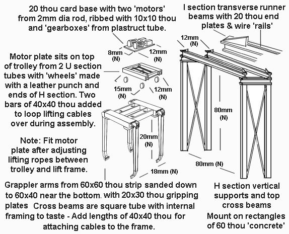
The lifting ropes can be 5 amp fuse wire but for convenience 10x10 thou plastic strip can be used (or indeed that trusty standby of military modellers 'stretched sprue' - Hold a plastic sprue over a candle then pull gently). Trim to length after it has set using nail clippers. Personally I would add a railed platform, set about four feet up, to the outside of one of the side support frames with a 'control box' of 60x60 thou strip with some 'controls' of 10x10 thou on top. By the 70's it was standard practice to use a trailing cable with push button controls but I think in the early 1960's a fixed position would be more likely. Do not forget to add the access ladder to this platform if fitted. To represent the winding drums lengths of fine threaded bolt two or three mm in diameter can be glued to the underside of the motor plate so the ends stick out to either side, the only snag with this is that the plastic rod 'lifting ropes' cannot be easily glued to the bolt.
Speedfreight operations were concentrated in a relatively small number of goods yards but within ten years the ISO standard container had displaced this service. BR may have equipped some of its fork-lift type trucks or larger mobile cranes with lifting arms for Speedfreight containers but I have not seen any reference to these. I have no idea how (or indeed if) the Speedfreight containers, which did not have lifting rings, were lifted from the delivery lorry at their destination. Speedfreight also built a number of larger containers, these had the standard Speedfreight lifting points but also a set at twelve foot spacing to match the new Freightliner grapple lift arms. The various designs of Speedfreight containers are more fully described in the section on Livery - Containers.
Faced with increasing wage costs and competition from the heavily subsidised roads British Rail researched alternative methods of container handling. One type which found employment was a light alloy metal container, almost a cube in shape but with a camber to the roof, which had a pallet type base for lifting with a large fork lift truck. These were used by McVitie & Price for biscuit traffic in about 1961, unfortunately I have not yet been able to identify the base colour for the container itself. They operated with purpose built road vehicles which appear in black and white photographs to have the same colour paint as the containers, essentially a 'Luton bodied' van with the rear section cut away. The containers had a single door in one end, when on the road lorry this faced the front and opened into the area behind the driving cab for access. To speed up the handling the railway wagons (and presumably the road vehicles) had four steel pins, one in each corner of the container bay, which engaged in pockets on the base of the container. This meant they did not require the side securing chains used on traditional RCH type containers and the vacuum braked wagons used (coded Conflat AB) had no chain pockets on the sides. They were carried in pairs on ten foot wheelbase vacuum braked wagons coded Conflat AB (of which only five were built. The wagon chassis was an open framework, the only difference from an un-bodied chassis being three transverse bars (roughly two inches square), one in the centre and one at each end, with the container securing pins mounted on the ends. Unfortunately this does make modelling an empty example rather tricky.
Fig___ McVitie & Price Containers and lorry
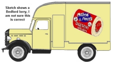
This sketch was made from a photographs on Paul Bartlet's website (see App 7 Useful Links)
In the later 1950's containerised transport at sea was starting to catch on and the International Standards Organisation developed a standard for these containers, based on an eight foot by eight foot end profile produced in multiples of ten foot lengths. ISO standard boxes have castings in the top and bottom corners of the frame with oval holes in them. The castings on the top have holes on the two exposed sides and on the top, those on the bottom have holes only on the sides. In use an oval headed steel pin is inserted into the hole and rotated to lock it in position, hence the common name 'twistlock'. Some containers have 'fork lift' sockets in the base but most of these are intended only for use when the container is empty. They should be marked but there is no standard marking as yet (the word tare on a coloured plate above the socket or (on closed containers) on a yellow arrow pointing at the socket, seems to be most common marking for 'only when empty'. Some containers are designed to be moved using a fork lift type truck when loaded, one example being the 'easidispose' waste containers discussed below. I have also seen 'flatrack' containers (a flat bed with fold-down ends) with four fork lift sockets, the inner pair marked tare, the outer pair unmarked and intended for use when the container was loaded. In general however containers are both moved and secured using the oval holes in the corners. For photographs showing loaded containers see German (insurance company) Container Handbook Website
ISO containers, being slightly too large for the standard British loading gauge, were originally transported by BR on drop-centred 'lomac' type wagons and handled in private factory sidings or, more commonly, at normal goods yards where a suitable crane was available. The height and weight of the ISO boxes meant that the existing manual goods yard cranes could not be used, these boxes had to be dealt with at yards equipped with a larger crane (generally this meant a gantry type) where they were transferred to and from road lorries. Ten foot long ISO standard 'boxes' can be lifted with a standard crane hook fitted with four wire-rope strops with hooks on the ends, the hooks being fitted into the top corner fittings. Twenty foot ISO containers were occasionally handled in this way but it was soon found that the twenty foot (or larger) containers required a lifting frame. The earliest such 'frame' was simply a single heavy spreader-bar slightly wider than the container with four steel wire strops suspended from it, two on each end. The lower ends of the strops were fitted with a spliced loop that was shackled to a hook that could be inserted into the bottom corner lifting holes on the container. As ISO standard lifting gear was rare in the early days some early containers were fitted with lifting lugs on the sides of the floor section to allow lifting strops to be attached using heavy shackles. Quite soon a rectangular steel box section frame appeared with four wire strops leading up to a lifting ring and four more that can be attached to the lower corner lifting points on the container. The next variant was a rectangular steel frame fitted with standard ISO 'twistlock' lifting lugs (which was lowered onto the top of the box and attached using the top mounted twistlock fittings) however I do not think this last design was used on the cranes in normal railway general goods yards.
Freightliner services began in 1965, carrying the new international ISO standard containers and Freightliners own containers between dedicated terminals, independent of the existing goods yards. Freightliners adopted the ISO eight foot square end profile but the original boxes were built in twenty foot and twenty seven foot lengths as thirty foot was considered too large for road haulage). The early Freightliner containers did not have the ISO lifting points on the corners, they opted for grapple lifting points (set at twelve foot separation) in the lower edges of the floor. This was a technology with which the railways were familiar as it had been used for the Speedfreight services. and when the special lifting cradle was not available eye bolts were fitted into the lifting points so that strops could be attached. If for any reason the container needed to be lifted where a frame equipped with these grappler arms was not available there was a threaded hole in the grappler pocket into which a heavy steel bolt could be fitted, this then allowed the box to be lifted by any suitable sized crane using a spreader bar with four cables.
The Freightliner service was built on the experience of the earlier container systems, these used specialised containers built for road-rail use and hence the containers were expensive and intensively used. As they did not expect their own boxes to be stacked in the yard the Freightliner built containers were not built for this. The widespread adoption of the ISO standard container changed things somewhat as the mass market brought economies of scale and competition between container manufacturers brought down the unit cost. By the mid 1970's Freightliners had switched to using the standard ISO container design with corner mounted lifting points.
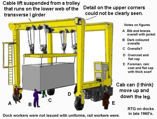
The Freightliner terminals were equipped with gantry cranes, spanning at least two rail tracks and the associated roadway. In several smaller yards the crane ran on pneumatic tyres, in larger yards they ran on rails, I believe the drivers cab on these early cranes was always on one of the gantry legs, not on the travelling motor section (more modern machines often span many more tracks and to aid visibility they have the cab suspended from an arm on the travelling motor carriage). Early container handling gear consisted of a set of frames which were suspended on cables from the gantry, basically the same equipment as used at the docks but carried on a smaller crane.
The sketch below was made from a photograph taken in the later 1960's. The mobile gantry crane was photographed at (I think) Southampton docks in the early days of containerisation, note the number of dock workers 'assisting' with the movement of the load, by the later 1990's the five men shown would probably be the entire staff of the terminal. Gantry cranes running on pneumatic tyres are usually referred to as RTG's or Rubber Tyred Gantries.
Fig___ Small Rubber-tyred Self Propelled Container Crane
The original Freightliner containers were not standard ISO types, they had no 'top lift' points and were handled using grappler points on the base. The original Freightliner gantry cranes were equipped with drop-down grappler arms that engaged in the lifting points at the bottom of the boxes in a similar arrangement to the Speedfreight boxes described above. These lifting arms folded up towards the centre as the frame was moved over the container and were then lowered into place for the lift. Some non-stacking containers, otherwise built to ISO specifications, still use the bottom lift points and require grappler arms on the lifting frames. Even in smaller Freightliner yards with limited on-site storage a straddle carrier or two would be provided (discussed below) to move the boxes onto stacks for later collection.
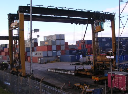
Freightliners operational practices are discussed in the section on Freight Operations - Air Braked Freightliner Container Services. That section includes several photographs of the RTGs and rail mounted gantry cranes used for these loads. The example shown below is a type that was widely used from the early days of Freightliner and remains in use in 2007 in a yard operated by Containerbase (a firm specialising in TIR international containers). The crane is wide enough to straddle two rail lines each with a roadway for lorries beside it.
Fig___ Small Rubber-tyred Self Propelled Container Crane in 2007
Vollmer offer the only really convincing RTG type container handling crane in N (kit number 7905) which is suitable for use on layouts from the 1960s to date.
When dealing with an ISO container the early cranes had to swop between ISO and Freightliner lifting frames but soon the frame became an adjustable arrangement, the grapple arms could be folded up out of the way when lifting an ISO box and the ends of the frame could be extended to handle different lengths of ISO boxes. The grappler arm approach has remained in use for loads which do not lend themselves to ISO container lifting methods, notably road semi-trailers that have been built to travel part way on railway wagons.
By the late 1980's one common standard crane in the bigger Freightliner yards was a large rail mounted affair with a vertical rectangular pillar passing through a rectangular lifting engine housing on the gantry and with the lifting frame attached to the bottom end. This type is easy to model but by this time the smaller Freightliner terminals had been closed down and those in use were all rather large establishments. Modern container terminals favour stacking the boxes anything up to nine high, so the cranes used tend to be very tall indeed.
The lifting gear has also evolved, early yards made do with rigid lifting frames which had to be changed to handle boxes of different sizes, by the 1970's the container lifting tackle was an extending set of frames able to handle 20, 30 or 40 foot long boxes, often with a set of grapple arms built-in to the design and operated by hydraulics. The ten foot container originally favoured by the US Army for stores never caught on commercially and I do not remember ever seeing one. To allow the operator to control the cable suspended hydraulically operated frame a hinged arm was attached between the frame and the carriage with a single elbow joint, allowing the arm to bend and straighten as the frame was lifted and lowered. This arm carried (from memory) two black cables or pipes about two or three inches thick. The cranes themselves have (I think) always been painted yellow all over and they usually have revolving yellow lights close to the wheels at each end to warn people when they are operating.
There are some small yards that handle containers, there was at least one in Scotland that has a single track running under the gantry. The crane was an old pneumatic tyred type but it sat on small concrete pads and did not move along the track. This yard handled containers for the former MoD RAF base in the area but it could have been used to handle the local coal delivery containers of the type operated by Russels.
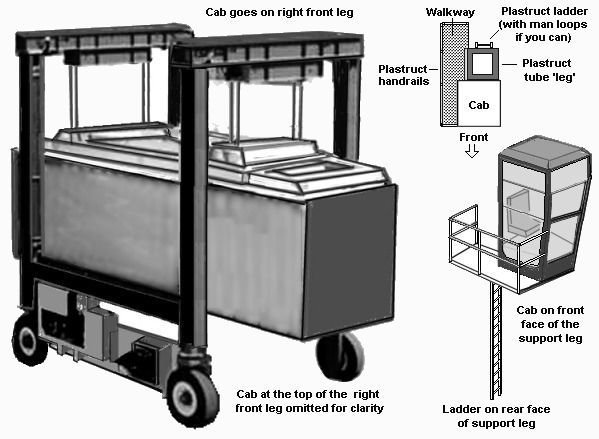
The ISO standard became a world wide success, which meant that people developed a range of container handling systems to suite the ISO standard. This has in turn lead to the development of a number of non standard containers fitted with ISO standard lifting and securing fittings. All these ISO compatible containers can be handled using either standard ISO container lifting gear such as the gantry cranes found in Freightliner yards or by various types of wheeled carriers. In crowded Freightliner and dock container yards a straddle carrier is often used. These have long legs with hydraulic motors driving wheels at the base and a set of lifting gear suspended from the rectangular top section. In use they are driven over the top of the container and a lifting frame is lowered to engage with the twistlock attachments on the top of the box. Early straddle carriers could stack the boxes two high, a few were built that could only lift the box high enough to load it onto the road trailer or railway wagon but these were rare. Since the mid 1980's four-high units seem to have become more common and six-high or higher are available. Stacking the boxes two-high in this way reduces the required storage area by almost 50 percent. The containers are stacked in rows, laid end-to-end, with gaps between the rows to provide access for the long legs of the straddle carrier and the resulting storage is relatively dense. On the example shown the centre section of the lifting frame is twenty feet long and handles twenty foot containers, the container shown is a thirty foot box which uses the extending ends of the inner frame. The inner frame can cope with thirty or forty foot boxes. The drivers cab is mounted high so he can see to position the container and cannot be crushed if he runs into a stack of boxes. I understand that more modern straddle carriers have the control cab positioned on one side but between the legs. I also understand that diesel electric straddle carriers are starting to catch on, in place of the diesel hydraulic type.
Fig___ Straddle Carrier
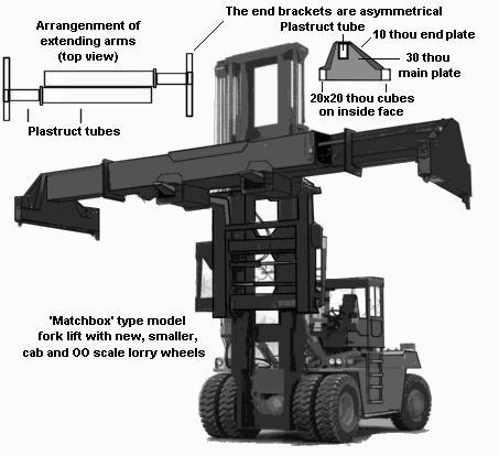
Where space is not so much of a problem, such as in yards handling a comparatively small number of boxes the preferred alternative was a large fork-lift truck type machine. These are now commonly called 'mast lift trucks' as they can be fitted with a range of load handling gear in place of the plain pair of forks. Some machines have a set of heavy duty forks that fit into sockets on the base of the container (although this is not I believe an ISO standard feature) or they can be fitted with a rectangular frame with ISO twistlock fitting in the corners. This frame is lowered onto the top of the container where the twistlocks are engaged using hydraulic power. These modern mast-lift trucks are big and in N gauge we have the option of using one of the cheap 'Matchbox' type models of a fork lift truck as the basis for one of these much larger machines. All that is required is some new wheels (OO scale lorry wheels serve well as the prototype wheels are rather large), a lifting frame (if required) and an appropriately scaled drivers cab (all these machines have an enclosed cab).
Fig___ Mast Lift Truck for Containers
The more recent alternative which has found widespread acceptance is the 'reach stacker', essentially a kind of mobile crane. This has an extending arm, pivoted at the rear and supported on hydraulic rams. The main advantage over the mast lift truck is the improved visibility as there is no mast on the front. Smaller reach stackers have the cab off-set to one side, they are used by farmers and the like and usually have a set of fork lift tackle on the end of the arm. Larger machines of the type usually used for containers tend to have the cab centrally mounted, under the rams and between the lifting rams. Reach stackers can lift containers onto two-high or even higher stacks (seven is the highest stack I have seen to date) and can reach over the top of one stack to lift a container on the far side. The reach stacker can have a range of lifting gear on the end of its arm and EWS has invested in at least one reach stacker with grappler arms built into its lifting frame for some of its new low density container and swap-body operations (see below). When not required the grappler arms swing up into the lifting frame as described above.
Fig___ Reach Stacker carrying a 20 foot container
Unusual Container Types
The BR London to Scotland MiniLink container services of the 1980's used non-ISO containers transported on purpose built wagons which could move the containers along the rake using a conveyor (this may be the origin of the name as 'Mini Link' is an established type of industrial conveyor). I am not sure how they were transferred on and off the train but I know the move took less than two minutes per box.
The more recent Mini Modal container system is also non ISO, the rectangular boxes were designed specifically for inland road-rail transportation and are not intended for international shipping. They have fork-lift sockets on all four sides of the base, so which ever way the box is placed on the wagon it can be lifted. At 2,55m (about eight feet four inches) square they require one of the more modern large fork lift trucks to move them.
Coal is now regularly `containerised', the containers used being designed to fit within the loading gauge when carried on four wheeled standard chassis. Similar boxes are also used for rock salt and all these containers have standard ISO lifting points in the corners. They are moved about in the yard by either mast-lift trucks with a top-lift frame or by reach-stackers. A model of a coal container is available from Taylor Plastic Models, mounted on the Graham Farish four wheeled modern air-braked chassis. See also Unit Loads - Modern Containers, Road Railer, Piggyback and Swap Bodies, Freight Operations - Coal and Freight Operations - Air Braked Containers - Non Freightliner for more information. These containers and most of the non-standard ISO boxes, such as the salt and potash containers built by Cobra Containers for Cleveland Potash, have sockets for lifting forks built in to the base. Where the coal or other material is to be stockpiled in a yard the containers can be stacked (I think the limit is three high but I could be wrong on that) but it is standard practice to lift the container onto a tipping road semi-trailer which is then driven to a coal pile and tipped.
Similarly waste disposal sites near major cities now use twenty foot ISO specification containers for moving compressed rubbish to land-fill dumps. These waste containers are built to standard ISO dimensions and can be handled with standard ISO gantry cranes similar to the equipment used in Freightliner yards or they can be moved using the big fork lift machines using the two sockets built into the base. There is an example of the former method at a North London terminal whilst the South Manchester terminal at Northenden uses a fleet of five fork lift machines for the work. The fork lift is also used to move the containers about on-site. Modelling these waste disposal terminals is more fully discussed in Volume 2.
The 'easidispose' containers used on the prototype operations have distinctive external ribbing, but these could be made up from Graham Farish unpainted containers or the kits of containers available from America.
Fig ___ Easidispose Containers
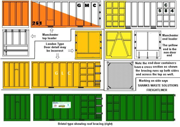
The sketches show two types, both twenty foot long, both have fork-lift sockets built into the base but the lower type has a lift-on hook at the closed end. This hook is used by a lorry equipped with a hydraulic arm, the lorry backs up to the container and the hook on the arm pulls the box onto the load area. To off-load the box the arm pushes it back and tilts it until it reaches the floor, then the lorry moves forward as the arm moves back until the box is left lying on the floor behind the lorry. This method of getting the box onto a lorry is commonly used for paper recycling containers and the procedure is an impressive spectacle.
Handling Swap Bodies and Semi-Trailers
The swap-body is essentially a container designed to ride either on a railway flat wagon or on a flat bed semi-trailer (usually the semi trailer is a skeleton framed affair built for the work). These have lifting points in the base so they can be lifted by fork lift truck or a crane with drop-down grappler arms (discussed above) that engage in the sockets. Similarly the road semi-trailers intended for use on rail wagons have grappler lifting points usually on the chassis. Both can be lifted by a standard container gantry crane (fitted with the grappler-arm attachment) but where one of these is not viable (such as in yards where the traffic is occasional or the layout does not favour their use) a fork-lift truck or reach stacker fitted with drop-arms can be used. Usually the drop-arms are incorporated into a container top-lift frame and can be swung up out of the way when not required. For a new terminal, where the long term future is uncertain, the wheeled multipurpose vehicles require less investment. EWS has purchased at least one reach-stacker equipped with a top-lift frame fitted with drop-down grapple arms for their swap body services.
Fig___ Fork Lift and Reach Stackers used for swap bodies and semi-trailers
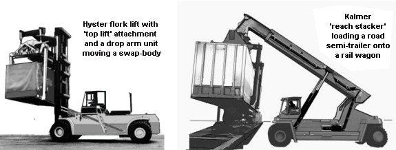
The Kalmer Industries type reach stacker, shown on the right, is the type used by EWS in its new container operations, whereas most such equipment is painted yellow Kalmer supply theirs painted pillar box red. The I section extending part of the jib (the bit that fits inside the rear box section) is painted dark grey on these cranes.
It should be noted that where the mast lift truck and reach stackers are employed the yard surface must be to a high standard as the axle weight of one of these vehicles when carrying a loaded container can approach sixty tons.