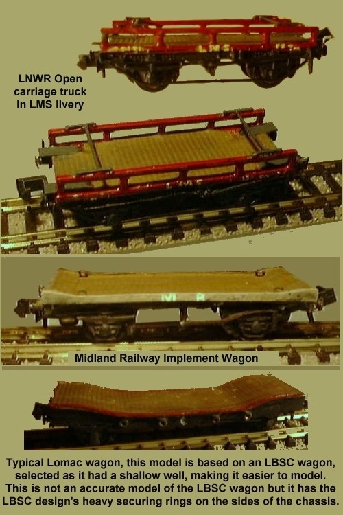
Specialised Rolling Stock.
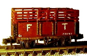
By 1850 small wagons were built with a single 'bolster'. A bolster is a
block of timber laid across the wagon to support the load, generally with a
vertical post or rod at each end to prevent the load sliding sideways. The
bolster wagons usually had a short wheelbase, typically seven foot, and a
single swivelling bolster mounted on a flat wooden deck. These were called
`single bolster wagons' and would be assembled in two's or three's or even
sixes to carry long loads such as timber and metal sections. Some wagons had
low sides (as seen on the Peco model) whilst others had no sides or ends at
all. The single bolsters were sometimes built as fixed pairs permanently
coupled together. These paired wagons sometimes had a combined buffer-coupling
between them although early designs had dumb buffers with a fixed chain
coupling. The Peco range includes a pair of single bolster wagons, but these
are on standard ten foot wheel base chassis suggesting they date from
immediately prior to World War Two. They can be cut down however and converting
these to the shorter vehicles is discussed in the section on 'Kit Bashing'.
Fig ___ Models of Great Central bolster wagons made using the Peco
kit as a basis
Modelling these and similar wagons was fully described in
Railway Modeller Nov 2001 (Traffic for Tickling Article 6).
From
about 1890 specialised vehicles started to appear in greater numbers in
response to traffic demand. Larger companies had forty or fifty different
designs of vehicles for specialised traffic but non-standard wagons were only
built in small numbers. There were large numbers of horses at work right into
the 1940's and several companies built manure wagons. The horses also required
a lot of hay and several companies built high sided open wagons to carry this
(the GWR provender wagons had higher sides than the then standard vans).
Most companies had a few
open wagons with a wooden floor but no sides or ends. They were usually fitted
with securing rings along the sides of the wood or steel chassis and were
intended to carry large objects. Introduced in the early twentieth century they
were never terribly common, from published material the North East had more
than other areas although the LMS built some of this type to carry planks of
imported timber. Most imported timber planks were Scandinavian soft wood, known
as 'deal' and these wagons were called 'deal wagons' by the LMS. British
Railways built a few of these open flat wagons (to an LNER design) in the
1950's.
By the early years of the twentieth century some bulk trades
justified the building high capacity wagons of up to 20 tons or so. As well as
coal and coke there was bulk traffic in bricks, hammerscale, road stone, slag, oil cake,
timber, manure and grain.
A high volume but low weight cargo was coke, large quantities of which were used
in a number of industries both as a fuel and as a raw material. Although the
value of coke was low the quantities involved justified the building of
specialised coke wagons. These resembled conventional mineral wagons but were
built with higher bodies. The sketch below is a Midland Railway coke wagon
design which saw service into the 1960's and possibly the very early 1970's.
Fig ___ Midland Railway Coke Wagon
Modelling these MR coke wagons in N was described in Railway Modeller
Sept 2001 (Traffic for Tickling Article 5)
Grain Wagons
The LSWR built twenty open eight
plank ten ton hopper grain wagons with curved raised ends in the 1890's. These
were used for grain imports from Southampton and lasted forty years before
being replaced. The tarpaulin covers on these wagons would only have been
removed for loading, so a simple box of scribed card with strapping detail from
10x20 thou microstrip, end supports from 30x30 thou microstrip and a paper
'tarpaulin' would suffice. The LSWR wagons had curved raised ends, these were
replaced by the Southern Railway in the 1930's with re-built wagons with patent
tarpaulin rails.
Fig ___ LSWR grain wagon in early SR livery
The GWR had experimented with various ways of handling bulk
grain. They had converted twenty or so ten ton standard vans for bulk grain
traffic, they then tried a 'convertible' eight ton open wagon. This latter had
a floor fitted with two hinged sections which lifted and laid back against the
ends to form a hopper. This was intended to reduce the empty wagon mileage by
allowing it to be used for normal traffic. Neither of these was a great success
but in 1927 they built twelve convertible twenty ton bulk grain hopper vans.
These grain wagons had a ten foot six inch wheel base but a body about
twenty foot long, inside was a double version of the hinged floor idea,
dropping into two discharge points underneath. The wheelbase was kept as short
as possible to allow the wagons to negotiate the tight curves in the docks.
There were two sets of heavily framed double doors on each side as well as the
grain loading roof hatches, the doors were fitted with heavy padlocks to avoid
some clot opening them when the van was full of grain. The twelve GWR vans were
switched to bulk cement traffic in the 1930's, at which time the side doors
were screwed shut and the roof profile was lowered as shown in the sketch. They
were re-converted for grain in 1940, at which time the hoppers were fixed in
place, the side doors were removed and the roof reverted to the high arched
profile.
Fig ___ GWR Grain & Cement Vans
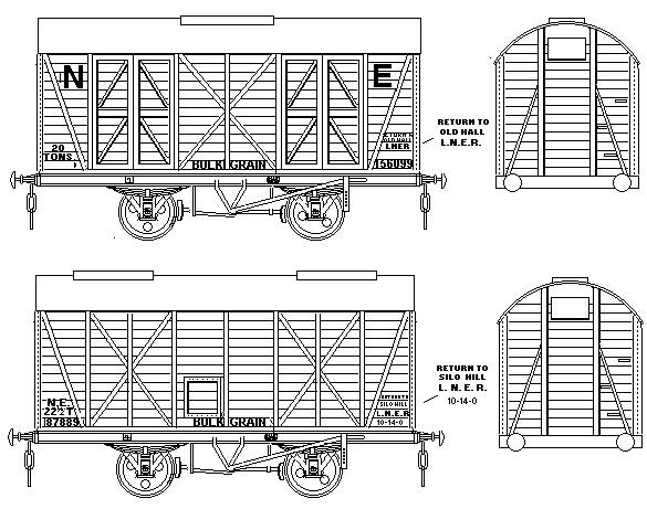
The LNER built twenty five grain vans to the original GWR
design. These vans proved popular but were seldom used for traffic other than
grain so when demand increased and further LNER vehicles were built these had a
fixed hopper and no side doors. The convertible types used by the GWR and LNER
were identical, the versions with no side doors differed only in the strapping
detail on their sides and the later LNER design had two roof hatches in place
of the original single hatch. Note the small inspection hatch on the side of
the later LNER van was fitted on one side only.
Fig ___ LNER Grain
Vans
The LMS inherited a number of bulk grain hopper wagons built
by the Midland Railway in about 1922. These were based on a standard Midland
van of the period, similar to the kit available from the N Gauge Society but
with the diagonal strap going the other way. In spite of the preference by
traders for wooden bodied grain hoppers the LMS built over a hundred grain
hopper wagons with steel bodies in the 1920's. The GWR built a small fleet of
twelve essentially similar steel wagons in the mid 1930's. Both designs were of
twenty tons capacity and retained the ten foot six inch wheelbase with the long
overhang at each end. The LMS version had external 'L' shaped strapping on the
sides whereas the GWR hoppers had smooth sides. These pre nationalisation bulk
grain wagons were used for imported grain, most British grain was still shipped
in sacks, transported in standard vans and sheeted open wagons.
Fig
___ GWR one-off, early MR/LMS and later LMS/BR and GWR/BR steel Grain Vans.
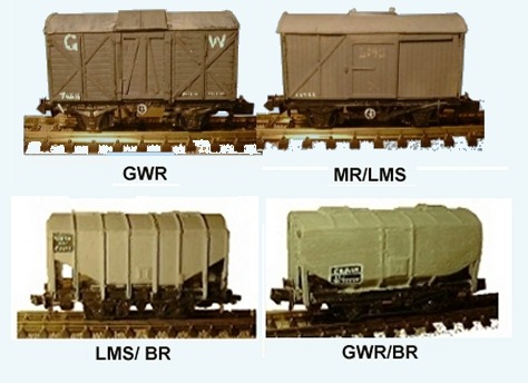
The GW wooden van was a one-off (built in 1905) but quite a few
of the MR/LMS vans were built. On the layout these wooden vans were used in the
docks at Fettling on Sea (the MR type were used in that way into the early
years of BR). The hopper discharge hand wheels are just Gimp pins (from a
sewing shop) painted black and with the rim and spokes in white. These vans all
had a single such wheel. The steel grain van models were made using the Peco
Grano long wheelbase grain hopper as a basis. This was after the possibility of
doing so had been pointed out to me by Alastair Knox of West Brent fame. These
also have Gimp Pin handwheels, but for some reason I photographed the wrong
side.
BR built their own steel bodied grain hoppers, very similar
in design to those built by the LMS although there were differences in the
outside strapping (the LMS had angle section across the curve of the roof, BR
used flat strapping, much easier to model). BR built a number of similar grain
vans on a slightly different vacuum brake fitted chassis. Modelling all these
variants is discussed in the section on Kit Bashing.
The photo below, courtesy of Dapol, shows their N Gauge BR era grain wagon.
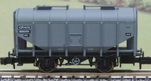
The LMS and GWR steel grain hoppers, and their wooden GWR and LNER predecessors, remained in use into the mid 1970's and were seen all over the country, so you can add a couple of odd ones to a rake of Dapol hoppers. The Peco `Grano' is a good example of the leased wagon, introduced in 1965 and built in batches up to 1971, the first batch was built by by Pressed Steel Co. for a company called BRT (British Railway Traffic & Electric Company, formed in 1907 and bought by Procor in 1974). These were painted all over blue and were mainly leased to the Distiller Co and used for hauling barley from the South East up to Scotland for the distillieries.
Beer & Ale Wagons
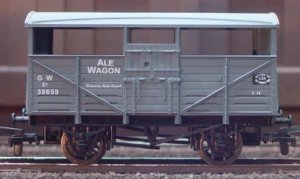
Several companies built or
converted vans for 'ale' or beer traffic, these were usually called 'ale
wagons'. The beer travelled in barrels and was not liable to weather damage,
but it had to be kept cool so the rolling stock used was well ventilated. The
Midland Railway built vans with open slatted sides similar to milk vans, the
Great Eastern converted some standard vans by drilling large numbers of one
inch diameter holes in the sides and ends and the GWR used redundant cattle
trucks. Cattle trucks provided plenty of ventilation with their open upper
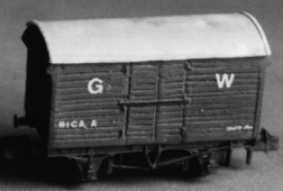
sides and gaps between the lower planks on the sides as described below. The photograph, courtesy of Dapol, shows their OO scale model of a BR standard cattle wagon re-branded for beer traffic.
Fig ___ Beer Vans
Livestock
Cattle trucks are called trucks rather
than vans because they were originally open wagons with timber rail sides. In
the 1890's the Board of Agriculture ruled that cattle trucks should be fitted
with spring buffers at both ends and better footholds and in 1904 rules were
introduced requiring cattle trucks to have a roof. Many companies had been
fitting a roof since the 1860's, prior to that date many cattle wagons were
open and at best had a tarpaulin stretched over the top to provide shelter. The
1904 rules stipulated a need for ventilation (the open upper sides common since
the 1850's served for this), openings to allow inspection at floor level and
that they should be fitted with falling doors to form an access ramp. The open
upper sides, usually with one or two horizontal iron bars, provided adequate
ventilation, inspection at floor level was already catered for in that wagons
had openings along the lower sides to allow the muck to be washed out and the
falling doors were already standard. Some companies interpreted the inspection
openings rather differently, leaving a gap of two or three planks in height on
the lower sides and fitting this with a railing of closely spaced vertical iron
rods. This latter approach is much more difficult to model.
Cattle
travel standing up so to prevent them being thrown about they had to be pushed
in so they supported each other. There were three agreed standard sizes of
cattle wagon, small (thirteen foot six inches long), medium (fifteen foot six
inches long) and large (eighteen foot long). By the turn of the century only
the large type was in production but this was fitted with a moveable partition
to convert it into a medium or small size. Livestock vans, along with fish and
milk carrying vehicles, were among the first goods stock to run in passenger
trains and express goods trains. Screw couplings and vacuum brakes were often
fitted to cattle wagons but there were also quite a number of unfitted wagons
in service and unfitted cattle wagons with a hand brake on one side only
survived into the 1930's.
Fig___ Models of cattle
wagons
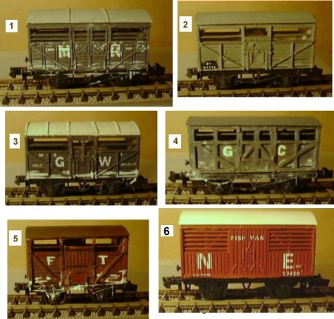
(1) Farish van in MR livery with added roof strips. (2)
Peco cattle wagon in unfitted BR livery. (3) Peco cattle wagon with added roof
strips and doors modified to represent the standard GWR design. (4) A Graham
Hughes whitemetal kit of a fitted GCR cattle wagon (mounted on a Minitrix
chassis as I made a mess of the kit chassis - This should have clasp brakes).
(5) A small cattle wagon made for a light railway layout, a shortened version
of a standard NER design (this appears to have been a commercial vehicle, used
by several companies). (6) The Graham Farish fish van looks like a goods wagon
but in practice this would most likely be part of a rake of fish vans or
possibly attached to a passenger train. The model is accurate but really should
have vacuum brake pipes on the ends and a vacuum brake cylinder mounted
underneath, it was actually a Great Northern design, to back date it just
replace the N E with G N. More information on fish traffic is included in the
section on 'Operations - Non Passenger Coaching Stock'. Horse boxes, which were
designed to run in passenger trains, were similarly classed as Non Passenger
Coaching Stock, as were 'prize cattle vans', which tended to broadly resemble
horse boxes but tended (from what I have seen) to be slightly larger.
One sometimes sees pictures of cattle wagons with white interiors and white stains on their sides caused by `lime washing' the insides of the wagons as a way of disinfecting them. The interior of these wagons should be all white and the liquid leaked out between the planks as well as through the built-in openings. There would be patches of white all over the body but mainly where there were gaps such as the openings at the bottom and around the open upper sides. This practice was banned in the 1920's, so the stains should not appear on Big Four or British Railways stock.
Perishables traffic in goods trains
Perishables, as
the name suggests, need to be transported quickly and efficiently. Milk and
fish are classic examples of this kind of traffic but as noted above these were
normally transported in 'passenger rated' stock, discussed in more detail in
the section on 'Operations - Non Passenger Coaching Stock'.
Meat,
fruit, butter, eggs, fruit and vegetables all required a lot of ventilation to
keep them cool in transit. Ordinary ventilated vans did not provide sufficient
air flow so special vans were built for this traffic with extra ventilation in
the sides and ends. Many of these vehicles were equipped to travel attached to
passenger trains (equipped with a vacuum brake and classified as XP (express)
stock). At times of high demand, such as the harvesting of seasonal fruits and
vegetables, cattle wagons were regularly pressed into service. These were often
fitted with a vacuum brake and the openings in the upper and lower sides
provided plenty of ventilation (but a tarpaulin was usually added over the top
of the vehicle to prevent pilfering). Open wagons were also regularly used for
this traffic, the load being covered with a tarpaulin or two. Some open wagons
were fitted with a raised framework to enable them to carry bulky but not very
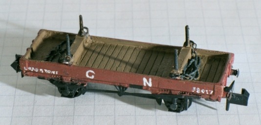
heavy loads such as vegetables. My model, built for a light railway layout, is
a slightly modified Peco seven plank wagon kit. The model is loosely based on a
wagon built by the Great Northern railway, the GN wagon was rather longer.
Making the frame and modelling the GN wagon (without the frame) are discussed
in the section on Kit Bashing.
Fig ___ Wagon fitted with
slatted frame for vegetable traffic
As the pattern of traffic changed over the years most
companies converted redundant rolling stock to cater for new traffic. Cattle
traffic had been in decline since the mid 1930's and the LNER and GWR had
experimented with converting cattle wagons for fruit traffic. The GWR
conversion involved boarding up the gap at the top of the side and fitting
standard vertically planked hinged doors, similar to the doors on the Peco
ventilated van. This was a successful conversion and further examples were
built by British Railways, still based on the standard cattle wagon but built
from new as fruit vans. Modelling details for this vehicle will be found in the
section on 'Kit Bashing'. The example shown is a GWR conversion in early BR
bauxite livery as it was fitted with a vacuum brake.
Fig ___ GWR/BR
fruit van conversion
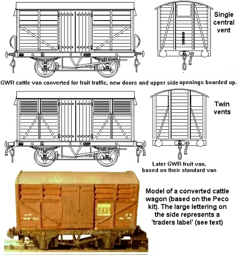
The model represents a converted cattle wagon with simple 'boarded
up' upper sides, the later versions had louvers (much harder to model) and
slightly different side strapping. An example is shown in the section on Post
Nationalisation wagon development. The model is based on a Peco cattle van with
a set of doors left over from another conversion of a Peco van (actually a BR
'tin can van' conversion discussed in the Section on Post Nationalisation wagon
development). The rectangular sign on the side is supposed to represent a
'traders label', this one was actually cut from the thin paper wrapper on a pot
of herbs. Traders labels are discussed in the section on Livery.
The photo below, courtesy of Dapol, shows their OO scale BR fruit van.
Sugar
beet was produced in considerable quantities after the First World War and at
harvest time it was standard practice to ship the beets in any available open
wagons, including coal wagons, to get them to the processing plants in time.
These wagons were not sheeted over when carrying beets.
By the end of
the nineteenth century steam power was having an increasing impact on
international shipping and live beef was brought in from Ireland and the
Americas. These animals were slaughtered at abattoirs close by the ports, the
meat being forwarded by rail. Ventilated meat vans were introduced in the
1870's and shipments of meat soon began to replace movements of live cattle
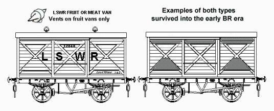
into the towns. The LSWR used a single basic ventilated van design for meat
vans and fruit traffic, both requiring similar handling. These outside framed
vans had gaps in the planking on the upper door and upper and lower sides but
these were covered by planked covers that were flush with the framing. The
fruit van had two roof ventilators, mounted on the centreline of the roof, but
did not always carry the word FRUIT on the door. These vans had lower than
normal roofs, which adds interest to a rake on a layout and some survived into
the early years of British Railways.
Modelling the more common version of
these vans (without the side ventilation, was described in Railway Modeller Jan
2002 (traffic for Tickling Article 7). To produce a meat or fruit van you
simply need to fill in the areas as shown on the sketch with Milliput and
scribe these to represent planking. The model described has a single end vent,
some of the fruit and meat vans were similarly equipped but other had up to
five vents on each end.
Fig ___ LSWR Meat/Fruit Vans
Ventilated meat vans equipped with hooks on which the fresh meat
was hung were built in some numbers, even small companies would often have a
couple of these.
With the arrival of chilled meat brought in by sea in
the later nineteenth century insulated and refrigerated meat vans appeared. The
frozen sides of meat were wrapped in Hessian cloth and stacked up inside these
vans. The GWR used a single basic design for both insulated and refrigerated
meat wagons. The N Gauge Society offer a rather neat kit of the type, complete
with transfers, but my model was made many years ago from a sanded-down Peco
'standard van' with planking scribed on the sides and end vent covers added
from scribed card bedded into Milliput. The photo was taken before the
lettering was complete.
Fig ___ GWR insulated and ventilated van
By the mid 1930's most meat traffic was carried in special
containers (coded BM) each carrying four tons of meat hanging on hooks. These
containers are sketched in the section on Unit Loads. The LNER used to see
entire trains of BM containers on special Conflat wagons travelling down from
Scotland to London, but the meat was often bruised in transit.
Bananas
became a regular cargo in the 1920's, they were unloaded from ships is an
unripe 'green' condition and shipped in specially built vans which were both
insulated and fitted with steam heating coils. The heating was applied as the
train made its way to the town and began, or accelerated, the ripening process.
The Peco ventilated van is a model of a GWR standard design dating back to the
late nineteenth century. The vertically planked doors on the Peco model were
introduced in 1927, the original design featured horizontally planked 'outside
framed doors'. The metal 'bonnet' end vents were introduced in 1912 and in 1919
some of these vans were lined with insulation to carry chilled cargo. The vents
were blanked off inside when the insulation was installed. In 1922 the vans
were modified to carry bananas which had to be heated in transit. The
insulation was retained but a new central vent was fitted to each end, and the
white spot was applied to help staff identify these converted vans. The livery
on the Peco GWR van is a hybrid, the lettering is correct for a ventilated van
but the big white spot was only applied to vans converted to carry bananas. For
a ventilated van the white spot needs to be scraped off but the remainder of
the lettering is fine. For a banana van the word 'ventilated' on the lower left
of the body needs to be changed to read 'banana van' (small white dots will do
for this).
The Peco 'Ventilated' van makes a passable BR banana van,
which was itself based on an LMS standard design insulated van derived from a
pre-grouping design which seems to have been used with minor variations by
several companies. BR banana vans had a yellow disk, eighteen inches in
diameter, with the vehicles tare weight on it in black in roughly the same
position as the GWR's white disk. The pre-grouping vans had only the top and
bottom hinges on the doors, but removing the middle pair without this being
obvious is difficult. The LMS vehicles were originally refrigerator vans with
roof hatches but with the change from water ice to carbon dioxide 'dry ice' the
roof hatches were removed. Similar vans but with a ventilator in each end were
built for banana traffic. In BR days the end ladders were removed.
Modelling the GWR and LMS/BR banana vans was discussed in Railway
Modeller Jan 2002 Traffic for Tickling article 7.
Long & High Load Wagons
As noted above the
first solution to transporting long loads was the rake of small wagons fitted
with bolsters. Introduced in the 1850's they were still being built in the
early 1960's but fell from favour soon thereafter. As iron and steel technology
improved wagon size was generally increasing and by the 1890's longer loads
were becoming more common, among them long rail lengths for which long wheel
base and bogie bolster wagons were built. 'Long rail' and 'Plate' wagons were
low sided long wheel base vehicles, designed to shift thirty foot lengths of
rail, large metal sheets or bundles of rods. They were also often used to move
agricultural machinery and smaller road vehicles as the drop sides meant they
could be relatively easily loaded from the side and did not require special
end-loading facilities. There is a photograph in R. J. Essery's book 'Midland
Wagons Volume One' showing a Rolls Royce motor car chassis being crane lifted
onto such a wagon in about 1920. The Peco range includes a long wheel base
plate wagon based on an LNER/LMS design dating from the early 1940's. The
chassis requires some work to improve this model but it can also serve as the
basis for a number of older designs, details will be found in the section on
'Kit Bashing'
The four wheeled plate wagons were often fitted with
bolsters and put into service to augment the existing single bolster wagons and
permanently coupled single bolster pairs. Again these can be modelled using
existing RTR wagons or kits, most of mine have been made using the Peco plate
wagon as the basis.
Fig ___ Peco Plate wagon converted into a Great
Northern twin bolster wagon.
Modelling this vehicle was described in Railway Modeller March
2001 (Traffic for Tickling Article 12). The 'chains' are made up from two
strands of 5 Amp fuse wire twisted together.
'Pipe' wagons were
built to carry clay drainage pipes (packed in straw). These were long four
wheeled wagons with four or five plank sides and a wheelbase of about twelve
feet. Parkside Dundas offer a kit of a 12 foot wheel base pipe wagon, a pre-war
LNER design which remained in service into the later 1980's. Some were still in
use in departmental service in the late 1990's.
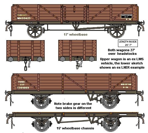
Even longer high sided
wagons were built after the First World War with wheelbases of up to twenty
foot. These were usually called 'tube' wagons (the Peco 'tube wagon' is a model
of a British Railways wagon built in the 1950's for use on train ferries to the
continent). The GWR 'tube' wagon, coded Open C, was a four plank design on a
fifteen foot wheel base, the LMS had a five plank wagon on a seventeen foot
wheel base with a central door and the LNER built some wagons on a fifteen foot
wheelbase with no side door. Modelling notes for GWR, LNER, LMS and British
Railways (steel-ended) tube wagons have been included in the section on 'Kit
Bashing'. Note the asymmetric brake gear shown on the ex LNER wagon was their
standard design for vacuum braked stock and was adopted by BR.
Fig
___ Pre-war tube wagons in BR liveries
Where long wagons were required to carry heavy loads a six
wheeled chassis was used although these were never really common. I have
described my way of modelling these chassis in the section on Kit Bashing. Some
of these six wheeler vehicles had surprisingly long lives, and a few of these
older vehicles survived into the 1950's. The six wheeled van shown was built by
the North British Railway before the First World War and lasted into the early
years of British Railways fifty years later.
Fig ___ North British
Railway 15 Ton Van 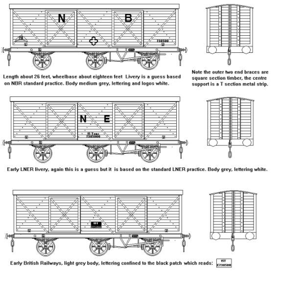
For carrying items that were more than about thirty feet long
bogie wagons were required. Most common were the bogie bolster wagons,
generally these carried four or five bolsters. These long wagons were in use by
the early twentieth century and bogie bolsters were built with up to seven
separate bolsters mounted on a single body. Usually the bolsters were removable
and there were often more mounting points than bolsters, allowing different
arrangements for different loads. Bogie bolster wagons were built in some
numbers just before the First World War and a number of fairly standard lengths
were established. Shortest were the twenty ton wagons which were typically
thirty five feet long, the thirty ton wagons were generally about forty five
feet long and forty ton wagons tended to be fifty to fifty two feet long. The
GWR built a few seventy foot long bogie bolster wagons in the pre-grouping era
but these were of course very restricted in routes due to their length. British
Railways built a number of sixty two foot long bogie wagons for carrying
lengths of rail coding them Borail. These were always assigned to the
departmental stock and were not used for commercial loads.
By the late
1960's bolster wagons of all types were used almost exclusively for steel
traffic. The single bolster wagons and pairs were phased out by the mid 1970's,
the four wheeled bolster wagons lasted only a few years longer and by the late
1980's only the bogie types remained in service. On modern stock steel bolsters
which fold down into the floor have been provided in some cases, these also
help to dissipate heat from freshly milled steel ingots.
The same
chassis were also used for bogie plate wagons although these were not so
common. Most bogie plate wagons were built with drop down sides, typically two
planks high and arranged in two half-length sections. Some of the bogie
bolsters were subsequently converted to plate wagons and on these the sides
were usually fixed. The N Gauge Society offer a plastic kit of an LMS
five-bolster bogie wagon which saw service into the 1970's. Several of these
wagons were converted to plate wagons with fixed sides two planks high by both
the LMS and British Railways.
Any items larger than about fifty foot
long or over eight feet wide were classed as 'special traffic' because of the
danger they might foul stock on adjacent tracks when in transit. These items
were rather rare in practice and would usually be worked through the system
during a low traffic period, usually over a weekend. Anything wider than about
eight foot presented a real problem on the railways, laid flat it would be
likely to foul stock on adjacent tracks and line side equipment, on end it
would foul bridges. To allow larger sheets of metal to be carried some four
wheeled and bogie plate wagons were fitted with a wooden trestle so the load
could be supported diagonally. This allowed loads of up to about 12 feet wide
to be carried.
Fig ___ Peco plate wagons converted to trestle
wagons
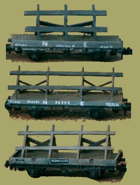
Modelling the BR and four-legged NE trestle
wagons was described in Railway Modeller March 2003 (Traffic for Tickling
Article 14). The model of the three-legged type shown here was an earlier
attempt and not quite up to the same standard. It was based on a drawing in
Peter Tatlow's book on LNER wagons (see Bibliography)
One
option for carrying tall loads was of course to lower the centre of the vehicle
and drop centered or 'well' wagons were built on both bogie and four wheeled
chassis One specialised variant on this theme were the wagons built to carry
road vehicles, these are discussed in more detail below.
The more
general purpose drop centre vehicles usually called 'trolley wagons' by
railwaymen. Unfortunately a lot of these wagons had an open framework with no
floor in the centre well, making a model of an unloaded vehicle a rather
difficult proposition. Most of the official photographs of these wagons are
taken from the side, so the floor is not visible, a little research is
therefore required when selecting a prototype.
Fig ___ Long and Low
Centre Wagons
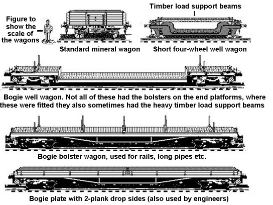
Fleishmann offer a continental drop-centred four wheeler in
their range which, although it does not resemble any particular British design,
can be pressed into service. Filing the sides of the floor plates so they are
parallel helps and for a British wagon the hinged side stakes should be
removed.
These vehicles are not impossible to model, especially if one
take a freelance DIY approach rather than trying to produce an accurate scale
replica of one of the prototypes. On the plus side they were often fitted with
removable longitudinal beams, mounted on raised bolsters on the end platforms.
Adding these beams gives a box structure which should cope with the average
model railway handling. Modelling drop centre four wheeled wagons is considered
in the section on Kit Bashing.
My model is based on the smallest type I
could find, a 1930's LMS design, as I wanted the look of the thing but did not
want it to take up a disproportionate amount of room on the layout. The
prototype was equipped with two heavy longitudinal baulks, as shown in the
sketch above, although these would not have been carried if, for example, the
load was a caterpillar tractor of some kind. My model was built with removable
timber baulks, one pair loosely wrapped in chain (set solid with glue), the
other pair with a ships propeller mounted between them. This was never a great
success as an idea as I failed to make provision for mounting the baulks using
locating pins and holes in the end supporting timbers, as a result the load
tended to wander off to the side as the wagon vibrated. I intend to repaint the
model in early BR grey and will probably just glue a pair of timbers in place.
Fig ___ Relatively short well wagon model
In the 1930's large steam powered and later diesel
excavators and bulldozers appeared. The railways had already built bogie and
four wheeled wagons with a very low dropped centre section to carry very large
loads such as boilers. The centre was dropped as low as possible, so it was not
practical to add ramps for end-loading but they could be used for the new
machines as their caterpillar tracks allowed them to be loaded from the side
and turned on the wagon itself. The low centred bogie wagons were called
Weltrol (well-centred trolley wagons) by British Railways and when fitted with
a trestle they became 'Trestrol'. Fleetline offer a kit of a bogie well wagon,
resembling a GWR design dating from the 1930's but running on Graham Farish
diamond frame bogies. They also offer the same wagon fitted with a trestle for
large plate loads. The N Gauge Society offers an excellent plastic kit of an
LMS bogie well wagon and the kit includes an set of etched brass trestles. In
the Bachman range is a 'fifty two foot' bogie well wagon which scales out at
about forty eight foot in British N. This model was originally supplied with a
'rocket load' but it is now also (I believe) available empty. This model,
although a few millimeters short, resembles a British 'Warwell' built in the
Second World War to carry tanks. These vehicles survived well into the British
Railways era, some being converted to carry steel by fitting them with raised
bolsters in the centre well. Parkwood models have now released kits for both
the Warwell and Warflat wagons (the latter are discussed below).
Heavy Loads
In the early days of the railways two
tons was a substantial load. By the 1840's eight ton loads were not uncommon
but anything over about fifteen tons was really too heavy for the track. By the
1850's solidly built six wheeled 'boiler trucks' were built to carry loads of
twenty tons and by the mid 1860's eight wheeled boiler trucks were built that
could carry forty tons. By the 1890's the use of armour plate in battleships
and heavy castings in industry had increased for which the railway companies
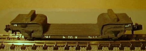
built increasingly heavy wagons. The example shown below was built by the Great
Central Railway at about the time of the First World War. This vehicle is a
practical proposition for the novice model maker, the chassis is a Peco brake
van chassis with the foot boards, running gear and coupling pockets removed.
The decking is a sheet of 1mm scribed card and the wagon runs on standard
Graham Farish diamond frame goods bogies.
Fig ___ Great Central/LNER
Armour Plate Wagon
For larger heavy items the railway companies built articulated
sets of heavily framed wagons with a total length of up to fifty foot. These
could be separated into individual wagons and used to transport longer loads,
but used in that way they would run as special traffic to avoid the risk of
accidents to line-side fixtures or stock passing on an inner curve. They were
usually called 'boiler trucks' by the railways but different companies had
different telegraphic codes (the GWR called the Pollen for example). No models
are commercially available for these wagons but a pair of Graham Farish tender
chassis could be used to produce something essentially similar. If you wish to
work the pair empty I suggest making up a couple of heavy timber beams mounted
on and chained down to the pivoting supports. Beams such as these were
sometimes fitted to these wagons to support a boiler or similar load.
Fig ___ Heavy Boiler Trucks
From the middle of the First World War the Army required railway
wagons to transport their new tanks but driving one of these over the end of a
standard design wagon in an end loading dock would exceed the maximum permitted
axle loading. To cater for this traffic the railways built, with Government
financial assistance, a number of bogie vehicles with supporting jacks built in
to the ends. These are usually referred to as 'rectanks', their standard
telegraphic code name. These wagons had a slightly dropped centre section with
the ends angled upwards slightly to the buffer beam. This makes them difficult
to model. Another military design from this era which ended up in general use
was the 'warflat', which did not have the dropped centre. During the Second
World War the tall American tanks presented a problem so a new design was
introduced. This was the warwell, a drop centred wagon with ends that curved up
to a flat section over the buffers. The Parkwood models range includes a kit
for the warflat and warwell wagons but I had a couple of Roco fish-belly wagon
(reference number 2352S) which I used to represent the warflat vehicles.
Warwell and Warflats remained in service well into the British Railways era.
Some of the shorter warflat wagons, only thirty four feet over headstocks, were
eventually converted to heavy strip coil carrying wagons, coded Coil K.
In 1926 the Electricity (Supply) Act was passed, which lead to the
development of the National Grid. This brought a requirement for large
electrical transformers and the railway companies built several special wagons
to transport these. The early transformers were of moderate size and the wagons
built to move them were roughly the same size as standard wagon. They usually
had a well or dropped centre section to accommodate the tall transformers
within the loading gauge. The size of transformers kept increasing, and in the
years before World War Two increasingly larger vehicles were built to move
them. Some of the later designs were heavily built contraptions with heavy I
girders running between six wheeled bogies, similar to the earlier wagons
developed for large naval guns and the like. These would be rare and as far as
I am aware there are no kits or suitable ready to run models available.
As the rearmament of the later 1930's gathered pace more armour plate
carrying vehicles were required. The LMS and LNER shared a common design twenty
four foot over headstocks and running on six foot wheelbase bogies. Introduced
in 1937 these fifty five ton wagons also carried billets of steel, heavy
castings and the like. British Railways built more wagons to this design and
also built a number of similar but longer wagons. These were still rated at
fifty five tons but they were thirty foot over headstocks and ran on eight foot
wheelbase bogies. These longer wagons were fitted with oval buffer heads.
Both types had a flat planked wooden deck and a simple I section steel
frame running on six foot wheelbase bogies. You could build the chassis using
two strips of Plastruct I section for the sides, glued to the underside of a
rectangle of 1mm scribed card for the floor, this however makes fettling the
buffer beans slightly more difficult. The generic coach bogies offered by
Graham Farish can be used at a pinch. The approach shown below works (I have
built bogie wagon chassis in the same way in the past) and results in a
stronger joint for the bogie mountings.
Fig ___ Armour Plate
Wagons
Glass Wagons
Special wagons with lowered centre
sections or 'wells' and supporting side frames used for carrying large sheets
of plate glass and larger ships propellers appeared in the 1880's. These wagons
were never very common but being little used they tended to have a long life.
The Great Eastern built only two glass wagons, one in 1899 the second in 1914,
but both survived into British Railways ownership. Plate glass was an expensive
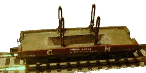
item, shipped packed into flat wooden cases. The NER glass wagon shown below
dates from 1896 but remained in use for many years, the supports stood about eight feet above the top of the chassis solebars, the sketch shows the vehicle in its post-1923 LNER livery (for modelling details see the section on
Kit Bashing).
Fig ___ Great Northern/North Eastern Railway glass
wagon
In transit a chain was added over the top of the load, secured to the side supports, when not in use these chains were left across the ends between the frames. As the load on the models were to be removable the chains were attached to the case. My model was made for a kiddie and had a removable load, as a
result I did not take as much care as I might have when making the well. On the
model shown the well is rather short, to make sure it did not foul the axles,
if care is taken, and the floor of the well is either sloped or stepped at the
ends a more accurate well can be made.
Fig ___ GN glass wagon
model
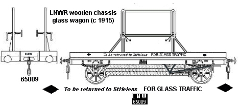
The LNWR operated some essentially similar wagons, although the brake gear was different (still operating on a single wheel on each side) and there was no cut-away at the ends. The supports were again about eight feet tall from the solebars (just over seven and a half feet above the wagon floor), and I believe they were closer together than on the GNR wagon (I could be wrong on that). On the LNWR wagon the supports had L section cross-bars at the top and bottom of the loops and diagonal supports at the base of the loops leading toward the wagon ends. As my model was for a child I felt these would be too vulnerable so he got the GNR version. The only photo I have seen of these LNWR wagons was captioned that they were withdrawn shortly before the grouping but I think that was a particular batch and similar wagons with a metal 'well' may well have been built after that time.
Fig ___ LNWR glass wagon
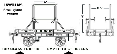
The LNWR also adopted a useful conversion of a one plank wagon, fitted with the same design of frame (again with cross bars at the top and bottom of the loops) and this represents a simple conversion to a Peco bolster wagon. The original design used a long-lever brake, operating on one wheel on each side, however as some of these short glass wagons, first introduced in the 1890s, survived into the LMS era you might get away with unaltered Peco brakes for a refurbished wagon. As I understand it the standard glass case was eight feet high and up to three feet thick (although most would be only about a foot thick), so these wagons had a thinner than normal floor to keep within the loading gauge.
Fig ___ LNWR short glass wagon
The LMS/LNER selected a joint standard design of unfitted glass wagon,
following established practice these had a sunken well in the centre section
and metal frames fitted with adjustable screw-clamps to the sides to support
the load. The British Railways plate glass wagon design was identical to this
twenty foot wheel base LMS/LNER vehicle.
The design of this
LMS/LNER/British Railways glass wagon makes it tricky to model but I have
included some ideas on this in the 'Kit Bashing' section. Glass wagons were not
numerous, but one on a layout would be acceptable, more if you have a glass
factory on or near your line (see Volume Two - Glass Works for details of
modelling these establishments). They were also used for occasional unusual
loads where their dropped centres were an advantage, such as steel sections and
coal mine pit-head winding wheels. There are photographs in various books of
British Railways wagons being used to move large metal rings with gear teeth on
the outside edge as part of a special train, this was actually a dismantled
cement kiln being moved from one location to another.
Fig ___
LMS/LNER/British Railways glass wagon 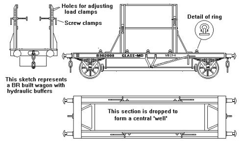
Wagons for Road Vehicles & Farm Machinery
Standard horse drawn delivery wagons and the like could be moved on any
open vehicle long enough to accommodate them. Most were shipped singly and
carried on flat wagons of typically of ten to twelve foot wheelbase. When for
example the army needed to move a number of such wagons bogie flat wagons were
used.
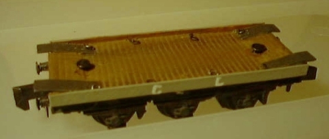
Wagons with low centre sections are generally called 'trolley
wagons', they first appeared in the 1870's and were used for carrying larger
road vehicles, farm machinery, boilers and other large loads. Depending on the
intended load these were called carriage trucks, implement wagons, machine
trucks, road vehicle wagons, furniture van trucks and boiler trolleys.
In practice those intended for commercial wheeled vehicles and
agricultural machinery were used on an as-required basis, depending on the size
of the load. Those intended for private carriages, and later motor cars,
usually had bars across the vehicles. In many cases these consisted of a timber
beam with a steel rail running along the top. The carriage or car was secured
to this bar using leather or heavy webbing straps. The example shown below is
an LNWR vehicle and this was slightly different. The loops that look like hand
rails on top of the side rails were ratcheted guides, in which moveable
brackets were fitted, to which the straps were attached. The cross-bars on the
model are tucked under the loops for strength, on the prototype these were bent
down at each end and fitted into holes on a steel plate. The steel plates were
fitted at each end of the side rails and extended for about a third of the body
length. The plates were therefore rather longer than the ratchet loops. The
securing straps are not modelled, partly because I was lazy but partly because
the wagon usually runs with a small car (from a Christmas cracker) as a load.
The straps could be represented using narrow strips of paper (about 0.75mm
wide), on this prototype they were a very pale colour, possibly white.
Machinery trucks in contrast relied on chains or ropes attached to heavy metal
rings attached to the floor, or occasionally to the sides of the solebars. Fold
down flaps were often fitted which bridged the gap over the buffers, so the
load could be manoeuvred onto the wagon in a special 'end loading dock' or
'carriage shoot' (discussed later under Railway Company Goods Facilities). On
some vehicles the buffers were covered by a fixed metal hood serving the same
purpose.
These vehicles sometimes had smaller than normal wheels and a
lower than normal floor, however they had to buffer and couple with standard
wagons so the ends were of normal height and the floor sloped down forming a
'well' in the centre. Where the intended load was not particularly large, such
as most farm machinery, the dip in the centre of the wagon was not very
pronounced. Modelling these vehicles is not difficult providing one is prepared
to accept a slight compromise in the design and this is discussed in detail in
the section on Kit Bashing.
Where the dip required was greater a longer
wheelbase was employed, allowing the ramped ends to be at a suitably gentle
angle. Models of these long wheelbase low centred vehicles (usually called
Lowmacs as an abbreviation for Low Machinery Wagons) are available from
Fleetline (a white metal kit) and N Gauge Society (a plastic kit). The
Fleetline 'Lowmac' is a British Railways built wagon but closely resembles
Great Western Railway and Southern Railway vehicles dating from the 1930's
(basically similar vehicles were in use from the 1890's). The N Gauge Society
kit represents a one-off vehicle built by a pre-grouping Welsh company.
Building a model of an LSWR vehicles of similar appearance is discussed in the
section on Kit Bashing
Fig___ Carriage truck, 'implement wagon' and
Lowmac models
The photo below shows a
Cheshire Lines Committee 6 wheeled furniture van truck carrying its intended
load. Note the van is actually horizontal when loaded, the apparent dip to the
rear is due to distortion caused by using a macro lens on a cheap camera (I
didn't have the model to hand to re-photograph).
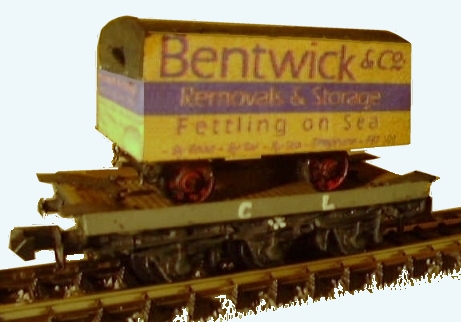
On the model the
sides are a constant height, forming a distinct well in the centre. This was
common practice up to the early part of the twentieth century but later designs
had the sides cut down following the contours of the floor and forming a slight
lip at either side of the well. This model was based on a drawing which did not
make it clear which kind of side was used, however as it required a removable
load, the higher sides were more appropriate. Modelling the van load is
discussed in the section on Cargo & Wagon Loads.
The floor of these
wagons was usually fitted with securing rings along the sides, examples were
built with four, six or eight such rings, and set into either end was a pulley.
Horses cannot push using standard harnesses so to load the van onto the wagon a
rope was taken round the pulley at the far end of the wagon, allowing a horse
to be used to pull the van onto the wagon.
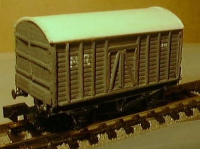
From about 1900 smaller road
vehicles and private motor cars were moved in vans fitted with doors at the
ends, these were usually called 'Covered Carriage Trucks' or CCT's. These CCT's
were intended for private carriages and motor cars and hence would often be
required to travel attached to passenger trains. They were therefore often
classed as 'non passenger coaching stock' and as such were painted in
simplified coach livery. Some of these were quite small, the Midland Railway
and later the Great Western Railway both built CCTs with a ten foot wheel base.
The small pre grouping vehicles lasted in service into the late 1930's, the
later Big Four designs remained in use into the early years of British
Railways.
With the increase in motor car production in the 1920's more
Covered Carriage Trucks were built and the wheelbase tended to increase. The
GWR built some longer wheelbase vehicles which they called Damo B (ten built in
1925, twenty foot over headstocks), Damo A (fifteen built in 1925 with another
twenty in 1929, thirty foot over head stocks) and Asmo (one hundred built in
1929/30, thirty three foot over headstocks). Although all three could be seen
in passenger trains not all were piped for vacuum brakes and they were classed
as goods stock by the GWR. P D Marsh offer a white metal kit of an SR utility
van which fits onto a modified Peco long wheelbase chassis. The kit is supplied
alternative end doors for the CCT version. Modelling various CCT's is discussed
in the section on Kit Bashing.
Fig ___ Covered carriage truck
models
The GWR 'Mogo'
motor car wagon (built from 1933) was a standard GWR van fitted with new ends
comprising two hinged doors and a drop-down section at the bottom, this can be
easily modelled using a Peco or P D Marsh ventilated van kit. My model is based
on the Peco kit, I carved and sanded the ends flat, scribed in planking detail
and added strapping from 10x20 thou strip. The P D Marsh kit can use new ends
made up from 1mm scribed card and microstrip details. Mogos were also used for
conventional traffic the vehicle securing equipment being stored inside the
van. The Midland Railway covered carriage truck started life as a Peco
'standard' van kit, new sides were added, recessed to allow the framing to be
added using strip.
During the First World War the railways moved
numbers of new aeroplanes in kit form. The fuselage would be shipped separately
from the wings and usually without the engine. The railways built and converted
a number of vehicles for this work including flat wagons on redundant four or
six wheeled coach chassis and CCT type vans. The vans were often marked
Aeroplane Van although they could also be used as CCT's. My aeroplane van model
was made for a 1920's light railway, it is based on an NER design but I needed
it in a hurry so I simply modified a Hornby Minitrix long wheelbase van, this
has the correct roof profile but is rather too long. A more accurate model can
be made using a cut-down Peco pallet van with the ends sanded flat and detailed
with strip and new sides from planked card.
Fig___ Aeroplane van
(freelance but based on an NER design)
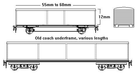
Where cars and light commercial vehicles were moved
in bulk, for example van chassis being shipped to the factory where the body
was added, the pre-war companies used old coach underframes with the body
removed and a simple wooden floor added. The LMS converted a lot of old Midland
Railway coach underframes to this use in the later 1930's. These vehicles offer
a possible use for Lima Mk.1 British Railways coaches which were under scale
length (about 57 foot instead of 62 foot)). You need to cut away the battery
boxes from the underframe trussing but this is not too difficult. If you have a
spare Farish 'suburban' coach underframe the job is even easier. The battery
boxes need to be cut from the underframe (this is easy as the frames can be
removed and the plastic is soft). I have not yet found a good illustration
showing the deck of these vehicles but I understand from correspondence with
members of the uk.railways newsgroup that the deck was made up of wooden
planking and securing lugs were fitted to the sides. These lugs were used for
straps which were passed round the axles of the cars (this was back when cars
had axles of course) Later BR built examples had channels in the deck and no
apparent lugs for securing the cars in place. All that is required for the body
is some Slaters 1mm scribed card for the floor and plastic card for the low
sides, for the later types with the channels in the deck three strips of
planked card laid onto a sheet of 10 thou card would serve rather well.
The Big Four had various telegraphic code names for these wagons but from about
1952 they were all coded Carflat and BR built further examples both for
transporting new cars from the factories and for moving private vehicles (ie
the Motorail service). Motorail services allowed people to take their car with
them on the train to save driving long distances. These latter services are
discussed in the section on Freight Operations - Non Passenger Coaching Stock.
The Motorail vehicles had a low side rail, this can be modelled using
brass rod or (if feeling lazy) by using thin brass rod for the rail and OO
scale brass handrail knobs for the supports. In the early 1980's Geoffrey Davis
rent-a-car also used carflats built for the Motorail service to move their cars
about the country (I was not able to find out when this traffic started or
ended however).
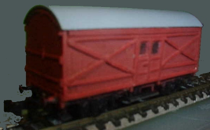
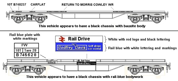
Fig___ Bocar for new cars (coded carflat) and a
Geoffrey Davis rent-a-car carflat
In the 1960's, 70's and 80's British Railways and the rolling
stock leasing firms built a range of specialised vehicles for transporting new
motor cars going to dealerships, these are described in the section on Air
Braked Rolling Stock.
Up to the 1970's there was a great deal of
inter-factory traffic in components. Some of these components were rather
large, for example it was quite common for one factory to build the chassis and
another to add the body. The chassis or the bodies were often moved by rail. In
the 1920's the GWR built some special vans with tarpaulin sides for carrying
car bodies from Oxford to Coventry. These were originally built on forty five
foot long 'Macaw' bogie flat wagons with characteristic heavy under trussing
and coded BOCAR but the loads were too light to justify using such heavy
vehicles. In 1934 a number of four wheeled coach underframes with lengths
ranging from about twenty nine foot to thirty two foot were converted for this
work (BOCAR B) and some thirty two foot bogie coaches (BOCAR A) were also
re-bodied for this traffic. More of the bogie A type were built just after the
Second World War and they continued in use into the early British Railways era
carrying car bodies from the Pressed Steel Company works at Swindon. The ends
on all types should be about 12mm high for an N Gauge model.
Fig___
GWR BOCAR
Modelling these vehicles is not too difficult, the chassis
for the four wheeled GWR vans presents the biggest problem but a Peco fifteen
foot brake van chassis with the foot boards removed and extended with a short
length cut from a similar chassis could be used. The Graham Farish fifty seven
foot coach chassis can be used with the battery boxes removed as described
above. The ends can be made from 1mm scribed card and the sides can be made
from paper or plastic card with a covering of crumpled and smoothed out
cigarette paper. The roof represents the biggest problem, you can roll one from
thin metal or for a plastic strip round a tin can using hot water but the easy
option is to beg a second hand Venetian blind and cute strips from that.
The LMS also built a number of Bocars, I believe these were broadly
similar in appearance to the bogie GWR types, but I am unable to confirm the
date of introduction or exact dimensions. Some LMS bocars were open car
transporters as described above, again I cannot confirm their date of
introduction.
There were also a number of air braked vans built for
components traffic, these are discussed in the section on Goods Rolling Stock
Design - Air Braked Stock.
High capacity vehicles
Railway vehicles up to
about thirty foot long could run on a single chassis with four or six wheels,
although the tight curves in some locations meant there were often restrictions
on the longer stock. Where heavier loads were expected or where the vehicle was
longer than this the body was mounted on separate swivelling trucks, called
bogies. Usually these bogies were four wheeled but where exceptionally heavy
loads were anticipated six wheeled bogies were built. One of the early large
dining coaches actually had eight wheels on each bogie.
In the 1880's
there were experiments with larger vehicles, interest having been provoked by
the success of large rolling stock on American railways. Several companies
built large bogie wagons for minerals, mainly for moving locomotive coal. The
GWR and the Great Central for example both used forty ton bogie coal wagons and
the Caledonian Railway built some bogie iron ore wagons with a thirty ton
capacity. The GWR Loco Coal wagon is sketched under Available Models, Graham
Farish, the GC and CR wagons are sketched below.
The large bulk mineral
wagons were relatively successful, but large general goods stock was restricted
to movement between major centres. Prior to the Second World War about ninety
percent of the freight traffic carried by the railways (other than bulk
minerals) involved large numbers of small consignments being shipped to many
different destinations. General goods took too long to load by hand into the
big vans and open wagons and it was impractical to hold a vehicle until it was
full. The four wheelers had reached an average twelve tons capacity a typical
wagon load was only about six tons, for which a fleet of smaller capacity
wagons was more efficient. In America where the bogie wagon had been developed
the pattern of freight movement was different, journeys tended to be longer and
the large capacity wagons were of more use.
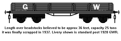
Few general merchandise
vehicles were actually put into service at the time (the GWR built a single
bogie open wagon) but the small numbers of large high capacity vehicles were
built at intervals for the following fifty years. The GWR wagon ended its days
carrying paper between Penarth Docks and a paper mill at Ely (near Cardiff).
The the sketch shows its final incarnation as a four plank wagon with two doors
per side, suitable for periods from about 1920 to 1937. The bogies were a plate
frame type similar to the old style coach bogies but with a shorter wheelbase,
these would be difficult to model.
Fig ___ GWR bogie open wagon
Thirty ton bogie open general merchandise wagons were also tried
by the Lancashire and Yorkshire Railway and Great Northern Railway.
Some traffic such as fish was by its nature suited to larger than
average wagons although these had relatively low payloads due to the way the
fish had to be carried to avoid crushing. Both the Great Central and North
Eastern railway built some very large fish vans, including some bogie stock.
The other disadvantages of large bogie stock were that it usually
required a locomotive to move it, the all-up weight was more than a lot of
industrial tracks could carry and clearances on curves in some locations were
too tight for them. Railway locomotives are expensive machines, steam engines
were relatively labour intensive and temperamental, men and horses were
generally readily available and considerably cheaper.
Even the bulk
minerals side had its problems with large wagons as the facilities for wagon
handling had been built with smaller vehicles in mind. A good example is the
coal hoists in the Welsh docks. These lifted wagons up a tower and emptied the
coal by tipping the wagon over a chute. The largest wagons the hoists were
designed to take were the GWR twenty ton four wheeled coal wagons and could
they not handle the much larger bogie wagons. In Britain the high capacity
vehicles remained very much the exception rather than the rule and it was the
1970's before larger vehicles became commonplace. They do however make
attractive models.
Fig ___ Large capacity vehicles
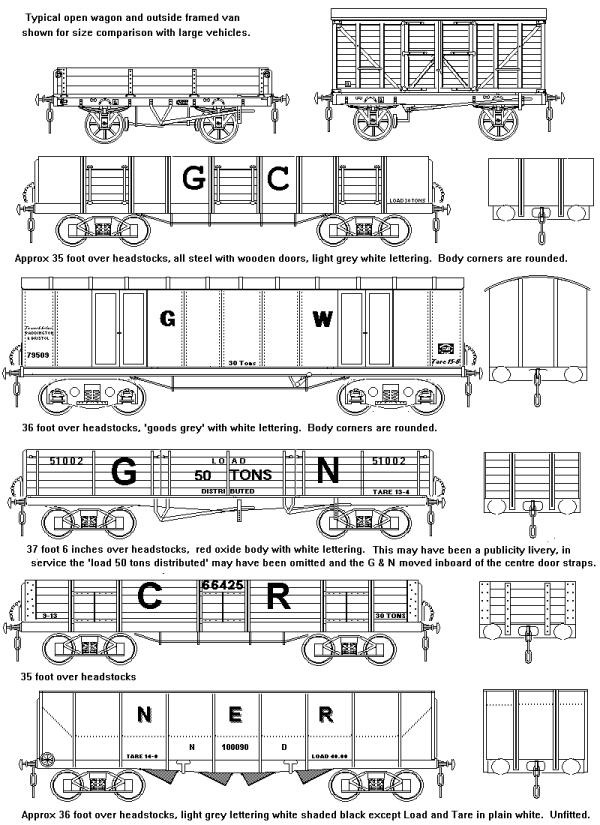
The sketch of the GC bogie open is from an illustration in a
book by O. S. Nock. This was a thirty ton all steel mineral wagon built by the
Great Central Railway around the turn of the century. Note the body overhangs
the sides of the chassis and the T section external straps are continued down
at an angle to the bottom of the solebars.
The iron bodied bogie van is
a Great Western Railway design, the first examples were built in 1904. These
vans were used for high speed goods trains from Bristol and Avonmouth docks to
London and Cardiff.
The Great Northern Railway open wagon was
introduced in 1921 specifically for the carriage of bricks from the brick
fields near Peterborough to the London market.
The Caledonian Railway
30 ton 'ore' wagon was used to supply the iron and steel works around Glasgow.
The North Eastern Railway bogie hopper was used to carry coal from a
colliery to Blyth docks, where it emptied into ships via a raised wooden
'staith'. There were about a hundred of these unfitted NER hopper wagons built
but they were run in short trains to suit the way the colliery worked. It is
worth pointing out that the Gross Loaded Weight of the impressive looking NER
hopper wagon was about fifty six and a half tons but the load carried was
smaller than the modern and much smaller PGA four wheeler 'aggregates' hopper
wagons.
^
Go to top of page
International Good Guys ~ Making the world a
better place since 1971 ~ Site maintained by

All material Copyright © Mike
Smith 2003 unless otherwise credited