In the 1830's most rolling stock had wheelbases of between four and six foot, wagon wheels were almost all spoked and made of various combinations of iron, steel or wood. The Liverpool & Manchester Railway settled on a cast iron spoked wheel with a wrought iron tyre and a wheel diameter of three foot. In the 1840's most of the L&M designs were adopted by other companies and the three foot wheel diameter became fairly standard. On passenger stock and some high speed goods stock slightly larger wheels were used, typically three foot six inches in diameter. Some wagons were fitted with smaller wheels, mainly those requiring a lower than normal floor such as farm implement wagons. There is a limit to how small the wheels can be however; a smaller wheel suffers more wear, generates more heat in the bearings and causes more damage to rail joints.
Early wheels had the tyres secured with rivets or bolts which tended to fail but in 1855 a dove-tail system was devised which was generally adopted. By the turn of the century tyres were continuous rings of steel instead of welded loops of iron, axles were made of 'Bessimer' steel instead of iron and the wheels were forced onto the axle using hydraulic pressure rather than being fixed with an inset 'key'.
Spoked iron wheels with separate steel tyres remained in common use on new vehicles up to the mid 1930's. Wooden centred, metal tyred 'Mansell' wheels, developed in the 1860's, continued in use on non-passenger coaching stock, horse vans and the like, up to the 1950's. These had a steel centre hub with a hardwood body and a steel rim and tyre. The wheels were pressed onto the axles in a hydraulic press and the tyre ('made from the best steel') was heated, placed on the wheel and allowed to cool and shrink onto the rim.
Rolled steel 'disc' wheels appeared in the 1920's and disc wheels with three holes in them started to appear in the 1930's. These one-piece steel wheels gradually replaced the older spoked types but spoked wheels were sometimes fitted to 'modern' British Rail rolling stock after repairs. Spoked wheels had virtually disappeared by the mid 1970's with the withdrawal of much of the older rolling stock.
One of the problems with iron wagon wheels was cracking. The railways employed men called 'wheel-tappers' to walk along the wagons in sidings and tap each wheel with a small hammer. If the wheel made a flat sound with no 'ring' it was cracked and the vehicle had to be withdrawn from service. By the late 1930's cracked wheels were becoming increasingly rare and in the early years of British Railways the wheel-tapper was phased out.
The British Railways Research Establishment at Derby conducted experiments on the design of wheels and bearings and one of their early findings enabled passenger trains to reach 100 mph. From quite early on the wagon or coach wheel had a slightly tapered profile, it was larger nearer the flange than at the outside edge. This was done so that when going round a corner the outer wheel would tend to 'ride up' onto the larger part of the wheel, the inner wheel of course would run down onto the smaller diameter part. The idea was to introduce a degree of 'differential', reducing the wheel slip and hence wear. On standard bullhead rail the chairs were arranged so that the rails leaned inwards slightly so the flat face of the wheel tyre ran along the flat top of the rail. The British Railways engineers tried making a wheel dead flat and found that this eliminated the side to side hunting motion that had dogged high speed trains for years. This flat tyred profile has been adopted by railways all over the world for high speed running.
Wheel Bearings
Early rolling stock was based on road vehicle design and used fixed, non rotating, axles with wheels mounted on hubs. An example of an early open wagon with spoked wheels on a fixed axle is preserved at Stratford upon Avon. These wheels can be modelled using Mike Bryant or Romford wheel sets with the end bearing filed flat and the axle passed through two short lengths of plastic tube glued to either side under the chassis. Note that a single long tube on the axle would probably stop the wheels revolving on a light N gauge vehicle.
By the 1850's, following experimentation with various forms of axle and bearings mounted either inside or outside the wheels the trend favoured a rigid axle and wheel supported between two end mounted axle boxes. The axle boxes were mounted in metal guides or frames called 'W' irons, in which they could move up and down. The W irons were bolted to the inside face of the wagon solebar. If you had ever wondered about the small curved plates seen on some chassis above the wagon wheels these were protective plates fitted to the outside through which the securing bolts for the centre part of the W-iron were passed.
The ends of the axles were supported in bushes in the axle boxes and these bearings were filled with grease or supplied with oil from a small reservoir. The oil filled axle boxes were more difficult to manufacture and for a time the grease packed axle box remained the standard. As speeds increased the less efficient grease filled boxes tended to run hot and oil filled types were further developed by the turn of the century. Grease boxes tended to be very square, oil filled types tended to be more curved, the wagon builders used different shapes of registration plate to show which type should be fitted so mistakes could not be made during repairs. In practice some wagons still ended up with a mix of oil and grease boxes but this was rare.
The oil-filled axle box, although an improvement on the grease filled type, was not perfect and overheating axle boxes remained a routine problem for the railway controllers. As recently as the 1960's during trials of the prototype Deltic locomotive the train (of loaded vacuum fitted sixteen ton mineral wagons) suffered three stoppages due to overheating boxes. The train weighed over a thousand tons and averaged 50 mph with top speeds of 60 mph and it was noted at the time that the oil-filled axle boxes were not suitable for the planned high speeds of the new railway.
In the early 1960's the British Railways development team looked at the 'roller bearing' which has a set of steel spindles inside the bearing in place of a smooth wall. This allows the oil to circulate more easily in the bearing and reduces the danger of over heating. The roller bearing had been pioneered in the USA and was widely used in Europe. The cross section below was scanned from a 1930s Carriage and Wagon Builders pocket book, where it formed part of an advert for SKF (the Skefko Ball Bearing Co Ltd, a Swedish company with offices in the UK).
Fig___ Cross section of roller bearing axle box
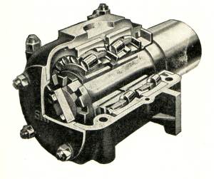
It soon became the standard for all new British rolling stock, and was often retro-fitted to older vehicles as well. As an example in 1983 the long wheelbase grain wagons (the Peco 'Grano' wagons, introduced in 1965) had roller bearings and auxiliary J Hanger suspension fitted. Roller bearing axle boxes are usually identified by having a circular yellow plate on the side in line with the end of the axle. This is actually the axle end and it revolves when the wagon moves but a blob of yellow paint serves well enough in N. Even roller bearings are not perfect however and occasionally an oil seal will leak and the bearing will overheat. As signal boxes have become much less common this has become something of a problem as the thing might run for some distance before the fault is noticed and this means that expensive damage can be done to the axle itself. The solution has been to use track-side 'hot-box detectors' to replace the eyes of the signalman.
One interesting design was the 'frictionless bearing', first experimented with in the 1830's. On these wagons the road-wheels were carried on an axle as normal but instead of being mounted in bushes the ends of the axle were fitted between two guides and in place of the normal spring there was another wheel supported in a standard bearing. Several revolutions of the road wheel and its axle resulted in on a single revolution of the bearing wheel and its axle bearing, the friction and heating in the bearing carrying the load was therefore greatly reduced.
Fig ___ Sketch of Ross' patent frictionless wagon circa 1830
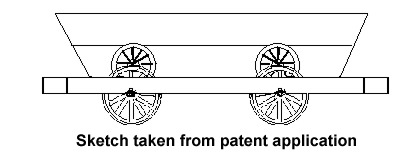
This worked quite well but the additional cost was considered rather too high and over the years very few such wagons were built. The pre-grouping North Eastern Railway had some thirty ton iron ore hoppers with this kind of bearing, and I gather some other high capacity four wheeled wagons were built with a similar arrangement, but I have not seen any definite references to them. Modelling these wagons would not be easy. Dummy non-rotating bearing wheels could be added to a standard chassis but you would need to carve away most of the normal axle box and altogether I suspect the resulting model would look rather poor.