Track Gauge &
Loading Gauge
The distance between the inner faces of the rails is
called the gauge. The first railway to use what became the 'standard
gauge' of four foot eight inches (1.4m) was the Willington Colliery
wagonway, built by George Stephenson in 1765, it used wooden rails
and flanged wheels. Subsequent railways built by Stephenson, such as
the Stockton and Darlington and the Liverpool & Manchester, also
used the four foot eight inches gauge. This changed to four foot
eight and a half inches as points or turn-outs were developed to
allow tracks to divide and join. This was by no means universal
however and in the 1830's there were lines laid with five or six
different gauges across the country and even today Glasgow's
underground railway system uses a four foot gauge track.
Early
Railways in other countries were in the main built by British
engineers or used British design philosophy and although 'metric'
most adopted the four foot eight and a half inch gauge. Not all
countries settled on the 'standard', Spain and Russia got their
engineers from Scotland and settled on five foot six inches (1.68m)
while Ireland opted for five foot three inches (1.6m). The widest
track I have found reference to in the UK was at an iron works at
Motherwell with a gauge of ten foot eleven inches (3.33m).
Brunel,
chief engineer of the Great Western Railway in the late 1830's,
developed a seven foot (2.13m) gauge, usually called 'broad gauge',
which was the only serious competition for Stephenson's standard
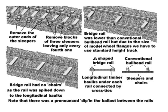
gauge. The track was laid as 'baulk road', as described in the section on Track - Development History this
consists of long heavy timbers laid under the rails with
cross-timbers at intervals to hold them apart and the wide track with
fewer cross ties gave these lines a very distinctive appearance. The
GWR was a successful enterprise and this seven foot gauge was adopted
by several companies in the South West of the country, the problems
came where goods had to be shifted from wagons on one gauge to wagons
on another, a practice called 'transshipment'. In the early years all
went smoothly enough but as traffic levels soared there were major
delays at the transshipment points and with the rapid expansion of
railways in the 1840's the question of gauges became a matter of
major debate.
The government set up a commission to look at
the question and in 1847 the 'Gauge Act' was passed favouring
Stephenson's gauge and referring to this as 'standard gauge'. The
seven foot 'broad gauge' developed by Brunel was effectively
prevented from spreading by this act. At the time there were about
two thousand miles of 'standard gauge' in place as against about two
hundred miles of broad.
Quite a lot of Brunel's broad gauge
track was altered to 'dual gauge' by adding a third rail but in the
1890's the last of the broad gauge lines were converted to the
standard gauge in a single large scale operation. Do note however
that much of the 'baulk' type track was simply modified, sections of
'baulk road' modified to standard gauge remained in use into the
1930's and a few sections were still seen in the 1940's. This
modified track had a distinctive appearance due to the comparatively
wide spacing of the cross-ties but it can be modelled using standard
Peco track if required.
Fig___ Baulk road modified to
standard gauge
Today the gauge is set at four foot
eight and three eighths inches (1.432m) and is maintained to an
accuracy of better than a tenth of an inch (2.5mm) to allow high
speed running.
Clearance between tracks
The Liverpool &
Manchester Railway of 1830 was the first line to use double track all
the way, they used left handed running on their double lines from the
start (only a few companies in Britain used right handed running and
these had all changed to left by mid nineteenth century). Stephenson
designed the track for the L&M with a gap between the inner rails
of the two tracks of four foot eight and a half inches, the idea
being that unusually wide loads could be carried on trucks running on
the inner rails of both tracks during slack periods. This left very little clearance between the lines and on the
opening day of the L&M an MP called Huskisson, who had
championed the railways, stepped down to stretch his legs at a
watering station and was caught between a coach and a passing loco.
This took off his leg and he died from his injuries, becoming the
first recorded main line railway fatality.
The distance
between the inner rails on double track lines was subsequently
standardised (more or less) at six foot (1.82m), widening on curves. Different companies adopted different spacings but BR standardised on six foot and today the standard is six feet six inches on the straight (again somewhat wider on curves). I am not sure when the extra six inches was added but I would guess this was in the early 1970s as at that time the new air-braked goods stock was built with slightly wider bodies than the existing stock. The gab between the running lines is sometimes referred to
as 'the six foot way' and railway staff often refer to the area
between the rails as 'the four foot'.
The distance between the running line and a siding was greater, BR settled on a minimum of ten feet as there was the likelihood of someone walking along the siding, for example a wheel tapper checking the wheels on the stock. Where additional running lines were added under BR the distance between these and the main running line was to be ten feet, although this could be reduced to nine foot where space was restricted, existing multiple track lines were not affected by this however.
This spacing set the upper
limit on the width of items that could be carried on the line as
allowance has to be made for trains carrying loads heading in
opposite directions. This allowance was further narrowed to allow for
what happens on curves when the centre of the outer vehicle, which is
'cutting the curve' passes the ends of the inner vehicle which are
riding directly above the inner track or possibly even extending
slightly beyond (although as noted above there was some widening of the space between tracks on the curves to increase clearances).
Loading Gauge
The 'Loading Gauge' is the maximum
size for rolling stock to allow clearance under bridges and between
tracks, especially on corners. It was established quite early on that the maximum width allowable for high speed running was in the region of 2.5 times the distance between the rails, on narrow gauge lines this is often exceeded but speeds tend to be slower. The British loading gauge reflects the
basic motivation of the original railway builders, namely to shift
coal and ores in bulk from place to place. In the UK the standard
clearance was therefore defined with relatively small wagons in mind. To refer to 'the' loading gauge is however misleading as it is only since the advent of British Railways that a national standard has been defined, and this cannot easily be applied to older lines built with smaller clearances.
The sketch below, scanned from a 1930's carriage and wagon builders pocket book, shows the average for England and Scotland and may be taken as a fair approximation for most mainland British standard gauge lines (a more detailed drawing, from the same source, showing the suggested details for British suburban passenger stock has been included in Appendix Three, under Loco Hauled Passenger Coaches).
Fig___ Average British loading gauges
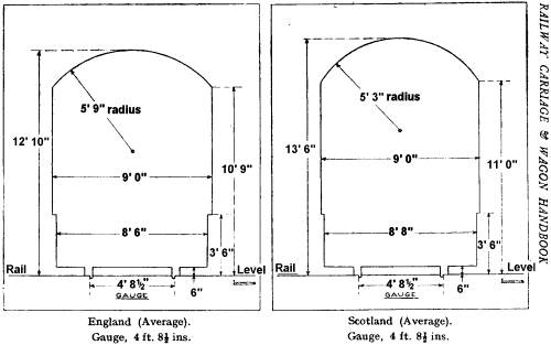
The loading gauge adopted as 'standard' by British Railways was based on the more common clearances on the pre nationalisation railways but at the generous end of the scale. As work was done on the line the clearances were increased, where possible, to conform to the national standard. This allowed a maximum width of about nine feet six inches up to a height of about ten feet and a maximum height of about thirteen feet six inches from the top of the rails in the centre. The Loading Gauge also specified the location of couplings and buffers, buffers were set five feet nine inches apart and set three feet six inches above the top of the rail.
Until the advent of the ISO rectangular container the biggest things on the railways were passenger carriages, on the GWR broad gauge lines some main line coaches were built that were about ten feet wide, at the opposite end of the scale were lines such as the SECR where coaches were typically only eight feet wide (the SECR also had their tracks closer together than most companies and as a result retained the rooftop 'birdcage' lookout for the guard long after other companies partly because there was no room at the sides for a look-out ducket). Even within a single company the actual loading gauge could vary a lot, the largest passenger coaches on standard gauge lines were those built for the Lancashire & Yorkshire Railway's electrified service between Liverpool and Southport which were a fraction over nine feet ten inches wide, but these were built for and confined to that route. When
the GWR changed from broad gauge to standard gauge their generous
clearances often allowed a second track to be run into goods sheds
and a third line to be run through double tracked stations on former
broad gauge lines. When they switched to standard gauge however they adopted a smaller loading gauge similar to other main line railways and built most of their stock to this smaller gauge to allow through running. The former GWR broad gauge lines have the most generous
clearances on BR with thirteen foot six inches (4.1m) vertical clearance
and nine foot eight inches (2.9m) width at the widest point but this is tight by European and American standards. In Europe they settled on a standard of
fourteen foot (4.2m) high by ten foot (2.3m) wide and in the USA,
where the main impetus for railways came from the need to shift beef
`on the hoof' from the Midwest, the loading gauge is about fifteen
foot (4.6m) by ten foot (2.3m).
Most British goods stock was roughly eight feet wide, possibly the widest single vehicle being the guards van with side look-outs and the BR standard van was only eight feet nine inches wide at the duckets. The widest early BR era goods vehicle I know of was the 'ferry high open' (as per the Peco long wheelbase tarpaulin wagon) which was eight feet eight inches wide over the side posts.
The air braked stock introduced after 1971 was rather larger, the standard four wheeled open wagons and vans were about eight feet ten inches maximum width to make them a better match to the standard pallet sizes. Curtain sided air braked vans for palletised traffic then ran into problems when the load was not properly secured, if it toppled sideways it could cause the side to bulge 'out of gauge'.
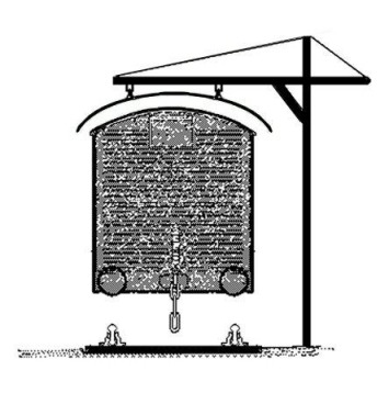
Some loads were light but bulky, bags of charcoal, nested stacks of empty fruit baskets and loose hay to feed the horses being examples, such loads could be piled very high on an open wagon. Spotting a load overhanging the sides was comparatively straightforward but judging its height was more difficult. To allow staff to check that loaded wagons would fit under bridges
and through tunnels a simple suspended frame, also called a loading gauge, was introduced. This consisted of a post with a curved rail
suspended from it, shaped to the clearances on the line. Virtually every railway goods yard had one of these and loaded wagons were passed underneath before dispatch to make sure they remained within the gauge.
Fig___
Typical loading gauge used in goods yards
Although broadly similar these devices were not all the
same, aside from the differences in construction and complexity
different lines were built with different clearances and individual
companies had differing policies. Where a station was jointly served
by two companies, say the LMS and the GWR, it was common practice to
have a loading gauge with hinged sections at the ends of the suspended bar which could be set for the
differing requirements of the two companies.
The loading gauge, in the sense of the clearance provided around the track, also affects the length of
railway vehicles. Long coaches and wagons, or long loads carried on
several vehicles, cut the corner on curves, also the ends of long
loads tends to stick out on curves and where two meet in transit a
collision becomes likely. Long loads could be accommodated but only
if they did not extend to the full width of the gauge, and even then
due to the nature of the tilt or 'super elevation' of the track
(which is 'banked' up slightly round curves) long and high loads had
to be carefully routed.
As a general guide anything shorter
than forty foot (12.2m) could be up to the full width of the gauge,
anything between forty and fifty foot (15.2m) long could be up to
about nine foot (2.7m) wide whilst loads between fifty and sixty foot
(18.2m) long had to be less than five foot (1.5m) wide. Anything
longer than sixty foot usually had to travel as a special train with
a time table that meant it never encountered another train on a
curve. In practice these widths were very much an upper limit and only applied on main lines, where branch lines or lines in industrial areas were concerned the upper limit on the width of a load was typically about eight feet. In the early twentieth century passenger coaches were built
with lengths of up to seventy foot (21m) and extending to the full
width of the loading gauge but these were very restricted in use.
Since the Second World War a number of lines have been widened to allow longer
vehicles and the current standard coach lengths are between 20m (65'
7") and 23m (75' 7") with the latter size still having some
restrictions on its use. There was a line on the South Coast, I think it was the branch to Hastings, where as an economy measure the clearances were made very tight indeed. One tunnel in particular was exceptionally tight and the passenger coaches for this line had to be specially built to fit within these tight clearances. I seem to remember there were problems with diesel locomotives, some being modified specifically for use on this line. Clearances on the Burry Port &Gwendraeth Valley Railway in South Wales were so tight that four wheeled passenger coaches remained in use up to the end of passenger services in 1953 and in the subsequent freight-only years class 03 and 08 engines had to be modified with a low roof to fit under the bridges (the line remained in operation for coal traffic until 1996).
Containers are a good example of how
the loading gauge can affect traffic. The original specification for
the modern rectangular metal container came from the US defence
department and specified a box eight feet high by eight feet wide. As the floor of a standard wagon is about four feet up the upper corners of the container were wider than the curved top of the loading gauge allowed.
They could only be transported on British lines using drop-centre
wagons or the purpose built 'Freightliner' low floored
wagons. Later containers eight feet six inches high appeared, for
which the clearances on British lines became a problem. Following a
great deal of work by Railtrack and some innovative designs from the
wagon builders the eight foot six inch high ISO container could be
handled on most of the railway network by the mid 1990's. Even
larger containers then appeared and a new variant the 'swap
body' (a container designed to function as the body of a lorry
trailer and built slightly wider than eight feet to better accommodate the standard European pallet) appeared and dealing with these higher containers and wide
swap-body traffic will involve a lot more work to increase bridge
and tunnel clearances. The revised loading gauge clearances required
to carry nine foot six inch high containers and lorry trailers to the
current maximum road size (fitted with special suspension to lower
its overall height when on the railway wagon) were generally referred
to as the PB Gauge standing for Piggyback Gauge. The clearances for
allowing nine foot six inch high containers to run on standard flat
wagons were rather smaller and the loading gauge clearances to permit
this were known as GB+ Gauge. There were plans are to modify two
lines from the channel tunnel to London where there would be a short
link line connecting the East and West Coast Main Lines, each of
which would be modified for swap-body vehicle clearances. This is in
line with a European plan for a high-speed railway freight system
extending right across the Continent then via the Channel Tunnel to
the industrial centres of Britain. The organisation sponsoring the
modifications to British tracks is called the Piggyback Consortium
(one of the vehicle types they are interested in promoting is a wagon
to carry road trailers and this is usually referred to as a
'piggy-back train' following American practice). At the time of
writing all this work is under review and may not be implemented.
Updated information
The Piggyback Consortium was
working with Railtrack on the project to improve clearances from the
Channel Tunnel and thence up the west coast main line (WCML) to
Glasgow. The plan to similarly enhance the East Coast Main Line
(ECML) to PB Gauge was shelved quite early on but as the WCML
provided access to the majority of proposed customers this was
accepted by the Consortium. By this time Thrall Eurospine trailer
carrying wagons were in service with EWS for Parcelforce trailers
between London and Glasgow, Freightliner had bought some trailer
carrying wagons from a company called Charterail which carried
specially built (smaller than normal in width and height) lorry
semi-trailers) and Babcock's first MEGA 3 pocket wagon was being
trialed by Freightliner. Both the Eurospine and the Mega 3 designs
allow standard width but low height trailers to be carried, they were
suitable for tanker trailers and trailers carrying heavy loads (these
being the only ones able to fit inside the loading gauge). These
wagons can also carry deep-sea containers and swap bodies.
Railtrack then (in 1998) decided not to bother with the
upgrading at all. The reasons for this change in policy were never
made clear however the Consortium noted that there was actually no
freight capacity at all south of Milton Keyenes during the day. The
limitations of network capacity following the various cutbacks in
rail routes since the 1960's meant that freight operating companies
(never as politically sensitive as passenger services) would always
struggle to find routes for their trains.
Railtrack then suggested
that a limited project to allow the carriage of nine foot six inch
high containers would 'satisfy the market'. The consortium pointed
out that:
Lorry
semi-trailers carry 74 per cent UK's road freight (measured in
tonnes-km in 1997), and the majority of these (about 75 per cent) are
built to the largest permissible size to enable them to carry the
greatest volume. They also carry 75 per cent of general cargo between
the UK and the continent. This preponderance of high-sided lorry
semi-trailers is evident on all major motorways.
It is this large
market for the highest semi-trailers that piggyback seeks to attract
to rail. With the exception of the niche but still significant tank
and heavy goods market, which can be carried by rail at present, the
customers (logistics service providers and many RHA/FTA members)
demand the greatest trailer height to achieve volume. They are not
interested in purchasing specialised equipment which carries less
volume just to enable it to be carried by rail.
The effective
maximum height for trailers engaged on international journeys is 4 m
road mode. On rail, with the air springs deflated, this height of
trailer plus the rail wagon just fits into PB gauge. It also happens
to fit just within the GB+ loading gauge, which is the standard in
all parts of Northern Europe and on selected routes between the
Channel Tunnel and Italy.
Deep-sea containers (boxes) are carried
between ports such as Felixstowe, Southampton, Tilbury, and Liverpool
to centres of manufacture or consumption. Their height varies,
generally between 8 ft 6 in and 9 ft 6 in.
Whereas the 8 ft 6 in
boxes are carried today on the main routes in Britain on standard
rail flat wagons, the newer 9 ft 6 in high boxes cannot be carried on
such wagons within the existing loading gauge.
The 9 ft 6 in boxes
now comprise 10 to 15 per cent of the market with this share growing
rapidly. If the railways wish keep their market share, let alone
increase it, they will have to raise the gauge height to accommodate
the 9 ft 6 in high boxes on flat wagons or build special low wagons
at extra cost. This new gauge (called here the "9 ft 6 in
gauge") is 230 mm (9 in) lower than PB gauge.
The main
market for piggyback is alongside congested motorways, particularly
the M1 and the M6. That is why Railtrack, at the time when it was
supporting piggyback, chose the West Coast Main Line for the
piggyback upgrade.
The 9 ft 6 in container traffic however needs
to access to major deep-sea container ports: Felixstowe, Southampton,
Tilbury and Liverpool. This particularly affects the
Nuneaton-Peterborough-Felixstowe and Birmingham-Reading-Southampton
routes.
Both the PB gauge route from Glasgow to the Channel
Tunnel and the 9 ft 6 in gauge for deep-sea containers to ports are
described in Railtrack's 1998 Network Management Statement.
We
understand that Railtrack has argued that a network of 9 ft 6 in
gauge routes as described above will be able to capture 90 per cent
of the "market". We question which market. If it is the
deep-sea container market, that may be correct in the long term, and
the proposed upgrade to 9 ft 6 in gauge on these routes is very much
to be welcome.
However, such a gauge can probably only cater for
less than 20 per cent of the lorry semi-trailer market which,
although welcome, is still only a niche in a very much larger market,
and on routes which generally follows congested motorways such as the
M1 and M6. These routes require PB gauge to make any significant
inroad into the lorry semi-trailer market.
Thus, there are two
very different markets, with some small overlap. They should each be
treated on their own merits, not mixed and confused.
Source:Memorandum by the Piggyback Consortium (IT 170),
MEMORANDUM OF EVIDENCE SUBMITTED ON 30 NOVEMBER 1998 TO THE HOUSE OF
COMMONS ENVIRONMENT, TRANSPORT AND REGIONAL AFFAIRS COMMITTEE
They went on to question the maths used by Railtrack
to establish the cost of the proposed upgrading. To the untrained
eye, such as mine, the basic problem seems to have been that
Railtrack were unwilling to undertake such a massive investment as
this was slightly risky and might not provide the benefit to their
shareholders that a less ambitious, passenger oriented, plan would
achieve.
Loads which are wider than the gauge are no longer carried
by rail but prior to the development of roads and road vehicles, and
the withdrawal of the common carriers legislation, the railways often
had to deal with such 'out of gauge loads'. When these loads were
moved through the system they had to travel as special trains and the
railway companies planned the routes for these loads with great care,
detailing points where they might foul adjacent sidings (which had to
be cleared) or where they might safely be passed by another train.
When moving exceptional loads such as bridge girders, it was
sometimes necessary to take the train onto the 'wrong line' in order
to put it on the outside track on a curve through a cutting or under
a bridge.
^
Go to top of page
International Good Guys ~ Buying calendars since 1971 ~ Site maintained by

All material Copyright © Mike Smith 2003 unless otherwise credited