Turntable points and slips are devices that connect two tracks together so that stock could move from one line to another. In the very early days of the railways points were prefabricated in a factory and supplied in kit form to be assembled on-site, by hand. Making points was pushing the limits of the technology, they were expensive to make and maintain and a fault would result in a derailment. They did allow an entire train to be drawn from one line to another but this required a gentle curve to connect the tracks. To avoid the use of points and save a lot of space the early railways made great use of small hand operated turn-tables to transfer rolling stock and even locomotives from one track to another. On a standard gauge line these would be circular and perhaps twelve feet in diameter, usually with two sets of tracks across then in the form of an X.
Turntables
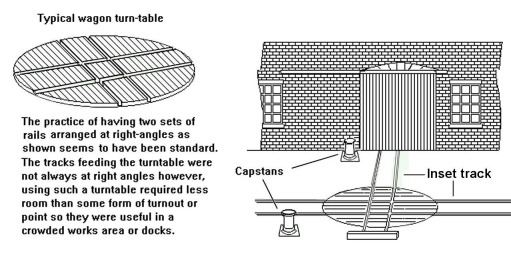
One point to note is that the tracks leading from the wagon turn-table need not be at right angles, in some locations several tracks converged and actually overlapped slightly where they met the turn-table.
The early railways often took a single siding into a goods yard, where a turntable then fed a series of sidings radiating out from it. In the mid 1830's the Liverpool and Manchester railway had over sixty such wagon turn-tables at it's Manchester goods depot, which by this time extended over more than four acres. Goods yards were generally re-laid with points from the later 19th century, but this required more space and occasional surviving turntables were seen in goods yards into the 1960s. One notable example being the station at Llanfairpwllgwyngyllgogerychwrndrobwllantsiliogogogoh on Anglesey, opened in 1848 and known locally as Llanfair P G, where a cramped site meant the single wagon turntable feeding several sidings in the goods yard remained in use up to the end of goods traffic in the 1960s.
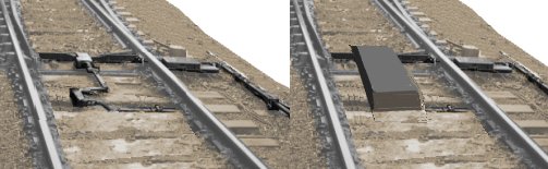
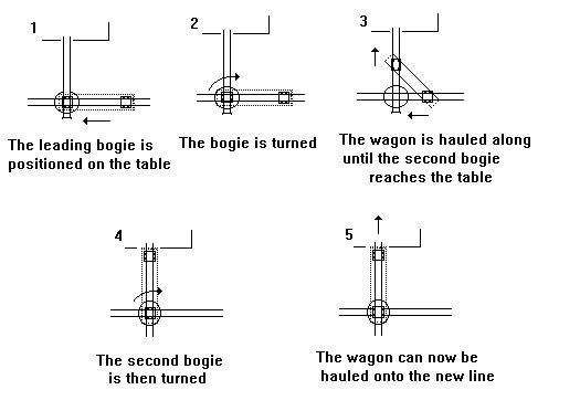
The typical small wagon turn-tables could handle wagons of up to about a maximum of twelve foot wheel base, anything longer represented a problem. By later nineteenth century the century several companies were using much longer wagons which were too big for the existing turn-tables. Large wagons mounted on bogies could however be handled on wagon turn-tables using the technique illustrated in the sketch below. First you position the wagon with the leading bogie on the turn-table (1), rotate this to line it up on the new track (2) and pull the wagon along, usually using ropes and either powered capstans or horses, until the rear bogie reached the turn-table (3), then turn this (4) so the wagon could be pulled off the turn-table (5).
Fig___ Wagon Turn-tables & Bogie Stock
Using turntables wagons could be transferred between tracks that crossed at right angles, which had several advantages in a factory or railway goods yard but by the 1850's it became apparent that the turn-tables were becoming a bottle-neck. With wear and tear they were not as reliable as had been hoped and they could only transfer a single wagon at a time, requiring a man or horse to move it. It was at about this time that the technology for bending rail using portable equipment such as hydraulic jacks became available, so that points could be readily made on-site and making them cheaper than turn tables. Thereafter points and other complex track formations started to appear in greater quantity, allowing locomotives to be used for shunting.
Turntables remained in use in many industrial locations into the 1950's and 1960's and the railways continued to use them in some large goods yards and in their own works. Probably the last turntables in regular use were on the dockside lines feeding coal tipping apparatus. They were required as wagons with an end-door at one end only had to be turned round to face the right way and they lasted until the end of the coal hoists in the mid 1980's.
In some locations the turn-table was located at the entry point to the factory (this arrangement appears to have been quite common at wagon works) however this did mean that locomotives could not be used to move the wagons as they were too big and heavy for the turntables. The British favoured fairly small four wheeled railway goods vehicles so individual wagons could be pushed about using man power but in busy locations such as town goods yards it was common to use horses or ropes run to 'capstans'. This saved running a locomotive and even after the turntables had been replaced the shunting horse and 'capstans' remained very common in British yards. A capstan is a revolving drum, generally with a `pinched' middle section, set on end and in railway yards they were usually powered by electricity. Some capstans were controlled by a lever operated clutch but others simply ran all the time, the rope was dropped over in a couple of turns and friction hauled the wagon into place. A skilled man could throw the rope over the drum and clear it very quickly, however accidents did occur. The last British railway installation equipped with capstans was completed in the 1950's.
One thing to note is that not all capstans were motorised, some were simply bollards placed so the rope from the shunting horse or from a powered capstan could be looped round them. These were provided where the track ran up against a wall or other obstruction to enable a horse (or a separate powered capstan) to pull the wagons right to the end of the siding.
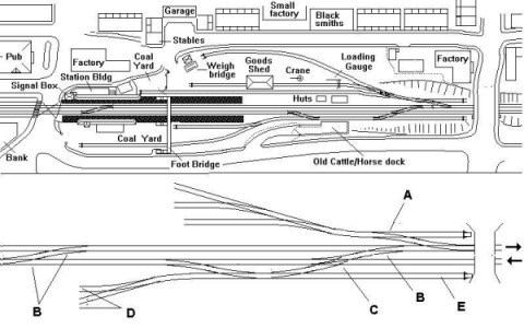
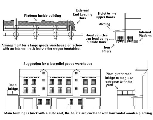
A single siding at a warehouse or factory might have a track running along one wall with a row of wagon turn-tables, each feeding a different bay. In some cases the bay would be a small dead-end recess or there might be further turntables inside a building serving tracks inside. This can be used to advantage as it makes the building appear more important than might otherwise be possible, an example of such an arrangement is shown in Fig___ below.
Fig___ Wagon turn-tables & Capstans
On some narrow-gauge quarry lines the wagon turntables were often very simple, one consisted of a simple circular metal table with a raised circular centre the diameter of which was the same as the gauge of the track. As the wheel arrangement on the quarry wagons was virtually a square this design worked well. These simple one-piece turntables are often called 'turnplates'
Fig___ Suggestion for using wagon turn-tables.
I have not yet seen a working wagon turntable in N (there have been a few in OO and O) however Peco offer a dummy wagon turntable in their 009 range, this can be used with N Gauge wagons but only as a cosmetic item. Some ranges of set-track include a 90 degree crossing, this can be cut down and used as the basis for a wagon turntable and would allow smooth running along the line.
Sector Plates
A variation on the turntable used for locomotives was the 'sector plate', this was a length of track sitting in a quadrant shaped pit and pivoted at one end (effectively a half-turntable). The free end was arranged to line up with (usually) two tracks and this was used on some passenger termini to allow a locomotive to be released and run-round its train. These sector plates were usually fairly small, only able to handle a large tank engine, although they a definite space saver they do require some skill to build.
Traversers
The final alternative to the wagon turntable was the 'traverser', a platform on rails sitting in a shallow brick-lined trough running at right angles to a row of sidings. A wagon was placed on the traverser and could then be moved to any of the other sidings it served. These were fairly common in goods sheds, as wagons were emptied they were moved onto the traverser and thence to a release road, so they could be removed from the shed without moving all the other stock still being worked on in the shed. There were also used in some passenger stations, notably at the end of a 'carriage shoot' where private road vehicles were being handled, this allowed each wagon to be unloaded without things having to travel through or across several other wagons. Larger version were also used in large railway establishments where locomotives and coaches were being built. Again I have not yet seen a working traverser (other than in a fiddle yard) for N Gauge but they are an easier option than a wagon turntable.
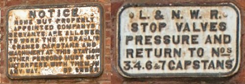
It was necessary to indicate to staff where the various controls associated with the hydraulic or electrical machinery were located, the cast iron signs shown below are typical, these were photographed at the Manchester Museum of Science and Industry, part of which is the original 1830 goods warehouse for the Liverpool and Manchester Railway, later part of the LNWR.