Track
Rolling a wheel along a prepared track or 'way' is an old
idea, the Babylonians carved ruts in stone paved roads to guide wagon
wheels along. This technique was also used by the ancient Greeks and
after them the Romans, who built some roads in Britain with ruts at
their standard wagon wheel spacing or 'gauge' of about five foot
(1.5m).
In the early seventeenth
century wooden tracked railways used wooden wheels with
flanges running on rectangular section rails (technically called
'edge rail') appeared at British mines and reached quite high levels of sophistication. In 1992 a
short section of wooden track including a set of wooden points, was
unearthed at the site of an old iron works at Bersham near Wrexham.
The track is believed to date from the early eighteenth century. The
rails were made of elm attached to oak cross-ties or 'sleepers', the
two being held together with wooden pegs, the gauge or distance
between the rails was just over four foot (1.22m). The word 'sleeper'
in this context dates from about 1789 and comes from Newcastle (where
many local terms are based on old Norwegian words), it has the same
root on Old Norse as the word 'slab'. The word 'rail' was
already in use for things made from lengths of wood and this is
probably the origin of the term railway (first recorded use 1681) or
rail-road (first used as a description in 1702).
The term
railway and tramway both mean the same thing, rail comes from the
French 'raille', tram from the Germanic 'traam', both meaning a
length of timber or plank. In Britain the term tramway became
associated with light lines operating on or beside conventional
roads, the tracks being commonly in-set into the normal road surface.
The term 'wagon way' was used to describe some early lines but from
about 1850 the British only used the term wagonway for light lines
using horses or men to move small wagons and settled on railway for
anything bigger.
Generally speaking the wooden track used at
mines in the North East favoured a gauge of around three feet whereas
those further south could have gauges of up to five feet. The
difference is believed to be due to the types of coal mine, the
deeper pits of the North requiring smaller wagons with necessarily
smaller gauge.
In about the 1730's people started adding iron
tyres and even iron spokes to wheels. Casting iron wheels or tyres
with a flange proved difficult at first and an alternative was to use
normal un-flanged wheels (usually fitted with iron tyres) running on
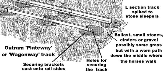
L section iron rails. This kind of track became known as a 'plate
way' and they were favoured by Benjamin Outram, one of the pioneers
of tramways in the late eighteenth and early nineteenth centuries.
Plate ways were initially used to transport goods short distances
from mine or quarry to a nearby canal but some lines were up to
thirty miles long. Outram favoured a gauge of four foot six inches,
which was also the standard distance between cart wheels in his home
area. He believed ordinary road carts could use his tramways but in
practice the reverse happened with his flat wheeled wagons being
dragged off the plateway for road delivery to the customer. L shaped
metal track was common by the 1870's, reaching the Welsh quarries and
mines in the 1890's.
The L section plateway rails were bolted
or spiked down to wooden cross ties (or sleepers) to keep them a
constant distance apart. This was building on existing technology
developed for the wooden railways in mines and quarries.
Unfortunately untreated wood had a tendency to rot and after about
1800 various people began using stone blocks laid in rows under each
rail. There was nothing linking the two rails together but the blocks
were heavy enough to prevent the tracks moving. Generally the L's
faced outwards and the stone blocks were usually either square or
roughly circular with a hole somewhere about the centre. A wooden
plug was driven into the hole and the track was secured to this with
a metal spike.
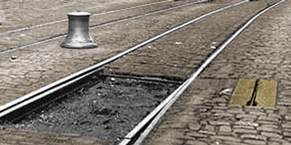
This L section track is of relevance to the
modeller because it remained in use for 'wagonways' into the 1940's.
These light lines were used for moving stone blocks from a quarry to
a railway loading bank and for small trucks carrying coal or ore from
minor mines to a nearby railway. Some of these lines used steam or
petrol engined locomotives but most used men and horses to move the
wagons. This kind of track can be represented using Plastruct
'fineline' (polystyrene) L section but this is really rather too
heavy and it is better to build up lengths from Slaters 10x20 thou
microstrip glued into an L section. Typically the rails would be
perhaps three foot (1m) long, often with the stone supports only at
their ends. The stone sleepers or setts were usually of fairly
regular shape, typically a foot or so (30 cm) across and one option
is to use a leather punch to obtain small discs from ten thou plastic
card.
Note you cannot use long strips and form them into a
curve, the rails were straight and curves were formed from a series
of 'dog-leg' bends, presumably using rails of slightly different
lengths. If you do make the rails from long lengths bend them at the
'joints' to form the curve. Normally, judging from photographs, on
long straight sections the sleepers seem to have been set in pairs
directly opposite each other.
Fig___ L shaped track on
stone sleepers
In
the early 18th century a firm in Shropshire produced cast iron
flanged wheels for use on wooden rails. In the 1760's an iron
foundry, again in Shropshire, started laying iron bars along the top
of their wooden rails partly to protect the rails and partly to
stockpile the iron plates. The men who did the work were called
'plate layers', a term which remains in use today for staff employed
in laying and maintaining railway track.
Crude cast iron
rails were first used by Richard Reynolds in 1762 but the ancestor of
the modern rail was devised by William Jessop in 1789 (Mr. Jessop
also introduced the first workable iron points at the same time).
Jessop favoured the flanged wheel with flat topped 'edge' rail over
Outram's L shaped rail and although he was in partnership with
Benjamin Outram the two seemed to have agreed to differ on this point
and their firm produced both types of track depending on who was in
charge of a particular project. Jessop's iron rails were made in
three foot (1m) to six foot (1.8m) lengths, there were side plates
cast onto the rail through which bolts secured the rail to stone
sleepers and the centre of the rail was of deeper section than the
ends. This is called 'fish-belly' rail and it was used for a number
of light wagonways from the 1780's.
Fish bellied rail was not
as common as the L shaped rails on minor tramways and wagonways
feeding full-size railway loading points but it remained in use in
some remote locations up to the 1940's mainly carrying horse drawn or
man-pushed mineral wagons. It is less easy to model than the L
section type and probably not a practical proposition in British N
although you might manage to glue short lengths of 10x10 thou strip
to the bottom edge of 10x20 thou strip. These rails were only made in
straight lengths so again if laying a curve from a single length of
strip remember to put it down in a series of 'dog legs'.
Fig___
Fish-bellied rail laid on wooden sleepers
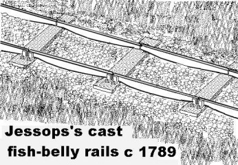
This sketch taken from a short length of preserved tramway
track, each rail is only about four foot long (1.3m).
In 1797
edge rails were cast with no built-in feet or fixing holes, these
were mounted in cast iron brackets called 'chairs' and the early
examples used wooden sleepers. This system of rails and chairs became
the norm for railways built after the beginning of the nineteenth
century.
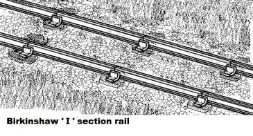
In 1820 an ironmaster called John Birkinshaw
patented an improved rail with a thicker section at the top and
bottom, forming an I shape and this basic design became the norm for
railway track. The rail lengths were laid in the brackets secured to
either stone slabs or wooden sleepers and a wooden wedge was driven
in to hold the rail in place. In early days the wedge was driven in
on the inner face, after about 1900 everyone changed to driving it
into the outer gap. This shape of rail and method of fixing became
the norm on British railways. In the 1970's the wooden chocks were
replaced with spring steel chocks.
Fig___ Light ' I '
section rail
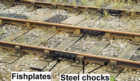
At the rail ends Birkinshaw added special chairs
to hold the rails together but in the 1840's someone came up with the
'fish plate', these comprise two short lengths of metal bolted across
the join at the end of the rails. The plates are just over a foot
long (30cm) and have four bolts passing through them. Two-bolt fish
plates were tried in the late 1930's so that the sleepers could be
placed closer to the rail ends and provide greater support, this did
not prove to be a success however.
The joints are where the
most problems occur in track and the unsupported 'fishplate'
joint suffered greater wear than Birkinshaw's joining chairs but
fishplates and bolts remained the standard system for joining rails.
Welded rail (discussed later) is now standard for all main line
tracks but fishplates are still used in yards or where points or
other complex track is joined.
Fig___ Photo of
bullhead I section rails joined with fishplates
Most of the wear on a rail happens on the top surface
but experiments with 'reversible' rails that could be turned over
were not a success as the 'chairs' which hold the rail wore on the
underside in use. This lead to the development of 'I' section rails
with a thicker section at the top called 'bullhead rail' which became
the standard in Britain until after the Second World War.
The
design of rails has evolved quite slowly as technology improved. Cast
iron tends to fracture and there was much debate as to the best
cross-sectional shape. One of the pioneering railway engineers, a
chap called Vignoles, designed an I section rail with a flat bottom
and a thickened top edge for the Liverpool & Manchester line in
the 1830's. Vignoles wanted to bolt the flat bottomed rail down onto
to timber strips running along the under-side to support it with
wooden cross sleepers to keep the rails the correct distance apart.
This arrangement for supporting the rail is called 'baulk road' and
in the South West I. K. Brunel used the baulk road idea for the Great
Western Railway. Brunel used an inverted U shaped rail called 'bridge
rail' for his track.
By the 1840's most British companies
were using bullhead rails carried in cast iron 'chairs' but in many
parts of the world the Vignoles flat-bottomed rail was preferred,
held down with spikes hammered into the sleepers.
The
very first steel rails used in the UK were laid at the Midland
Railway's works at Derby in 1857 but they were thrown away after
sixteen years service. There was some initial doubt about using steel
for rails because although it lasted much longer at the time it had
no 'scrap' value. This soon changed however and from the 1870's
rolled rails of 'Bessimer' steel had become the norm for all new
track.
Rail is supplied to the railway company in straight
lengths and is transported in this form through the system. The
standard rail length stabilised at about thirty foot (9.1m) until
after the First World War when forty foot (12.2m) and forty-five foot
(13.7m) rails appeared as steel rolling technology improved. By the
1930's sixty foot (18.3m) rail lengths were standard on main lines
and rails of up to a hundred and fifty or so feet were supplied to
the LNER and LMS companies. With Nationalisation the sixty foot rail
was adopted as the standard. Longer rails required longer wagons to
transport them and bogie designs were introduced by several companies
as rail lengths increased.
Rail taken from Peco or other
track is not suitable for representing rail loads on wagons as it is
way over scale. The best option is to use the finest 'I' section from
the Plastruct range (reference BFS-2), do remember that all the rails
would be of the same standard length and take care when cutting.
Where curves and complex track such as points and crossings
were needed they were made on the spot from standard rail lengths.
Teams of men cut the rail with hacksaws and bent the rail with
levers, chocks and pulleys, power tools did not exist so every hole
had to be drilled in the metal using hand drills.
As the
train passes through the curve the most wear occurs on the inside
face of the outer rail. To help reduce the wear on very tight curves
some companies added a felt pad, laid against the rail and with its
bottom edge sitting in a trough of oil. As the wagons passed they
pressed the felt, picking up some oil on their flanges as they did
so. An alternative system employed small plungers, operated by the
wheel flanges, which squirted grease onto the rail side. Even with
the lubrication the rails tended to wear and standard practice was to
exchange the inner and outer rails every few years to even the wear.
Rails are defined by their weight per foot or per yard and
the weight of rails has risen steadily over the years. Early lines
used iron rails of as little as forty pounds per yard, quite soon
steel rails of eighty pounds per yard appeared and by the turn of the
century everyone was using ninety odd pounds per yard for new rail.
In the early twentieth century, following an accident at a major main
line junction, it was found that rails ranging down to forty pounds
per yard were still in use, prompting the companies to check and
replace the older track. In 1921 the Government laid down a national
standard of ninety four and a half pounds per yard plus or minus half
a percent (this was in fact slightly lighter than the GWR's standard
rail at the time). These days the rail weight is not nearly so
standardised I contacted Railtrack on this in 1999 and they advised
me that although they could quote for specific sections the data for
the heaviest and lightest on the network was not directly
available.
I enquired on the newsgroup uk.railway regarding
the actual weight of rail and received the following replies:
I
thought Railtrack standardised on UIC60 rail (60 kg/m) some years
ago, at least for new main-line schemes. However, I don't know
whether they continued to buy earlier specs for replacements on other
lines.
Roger
UIC 60 (60kg/m) only seems to be used
on the higher speed main line routes, the only places I've noticed it
is on WCML renewals, although it may be used elsewhere. Otherwise
most renewals I've seen still seems to be using Flat Bottom 113A (113
lb / yd) on F 40 sleepers or EF 28 sleepers on Southern Region. (It
seems the use of "zone" has been discontinued)
All the
UIC 60 I've seen has been laid on G 44 sleepers with pandrol fastclip
fixings, but as I've never actually re layed any I couldn't say if it
can be laid on F 40 type sleepers for standard re railing or whether
its use requires G44 sleepers and therefore is only practical for use
on renewal projects. (There may also be load gauge issues associated
with its use for re railing as it is a deeper profile.)
HTH,
Kevin
To put these comments in context with
the earlier figures 60kg is 132 lbs and 1m is 1.09 yds so UIC60 track
weighs in at 121 lbs per yard. UIC60 rail is a heavy duty rail and
has been approved by the International Union of Railways (UIC) for
use on high-speed lines throughout Europe.
The payload of
goods vehicles has increased steadily since the Second World War, in
1948 the maximum weight per axle was seventeen and a half tons. This
was increased in 1962 to twenty two and a half tons giving rise to
the 'big' forty five ton wagons such as the Peco long wheelbase tank
wagon. In 1966 the axle weight was again increased, to twenty five
tons, but initially this was only on specific routes. By the 1990's
most of the network was allowed to carry twenty five tons per axle
and on some routes greater loads are permitted, allowing the very
large one hundred and two ton bogie tank wagons to operate.
In
the days of steam hauled trains the heaviest element in the train was
normally the locomotive, differing weights of rail and the strength
of viaducts and bridges under the track all contributed to
restrictions on the use of the heavier locomotives. Each line was
classed in a table of 'route availability' (usually abbreviated to
RA) on a scale of one to ten. The locomotives were similarly
classified and were allowed to operate only on lines which were able
to bear their weight. Typically the locomotive would have a coloured
disk painted on it to indicate the minimum RA class on which it could
safely operate.
Post privatisation Railtrack retained the RA
classification system, although it is normally the freight vehicles
these days which push the limits of the per-axle weight.
Track
rated at RA1-6 is the most common and can carry up to 20.3 tonnes per
axle, RA7-9 allows axle weights of up to 24.1 tonnes and RA10 can
carry up to 25.4 tonnes per axle. in the 1990's RA7-9 was used
for a network of freight lines around London, for the West Coast Main
Line up to Carslile and in areas where there are industries which
generate heavy freight flows. RA10 was confined to a couple of lines
in Scotland, a similar number in Wales and a number of short sections
which regularly handled very heavy freight.
As noted above
the joints in a track are where most of the wear occurs to both rails
and wheels, nearly half the work done on conventional track is in
maintaining the joints. Modern practice favours the use of long
lengths of welded rail, made up of standard sixty foot (18m) lengths
with their ends welded together to create continuous rails of up to a
mile or so (1.6 km) in length. Welded track offers not only a
smoother ride but also, thanks to the reduced number of joints,
requires much less maintenance.
Welded track was originally
developed in America in the late 1930's, notably on the Delaware &
Hudson Railway in 1937 where it was known as the 'Velvet Track'. In
America they tried welding lengths of line up to half a mile long
then transporting this on a fleet of wagons to the site, they found
the long rails curved easily to follow even quite severe reverse (S
shaped) curves. In Britain some long rail sections were moved on long
rakes of redundant long wheelbase twin bolster wagons (similar to
those offered by Peco), purpose built rail carrying wagons have always been used by the railways, where long lengths of welded track are used these are carried on specially designed bogie wagons. The photos below show such a train comprised of JZA wagons passing through Manchester on a rather dull winters day in 2005.
Fig___ Photograph of a welded rail train
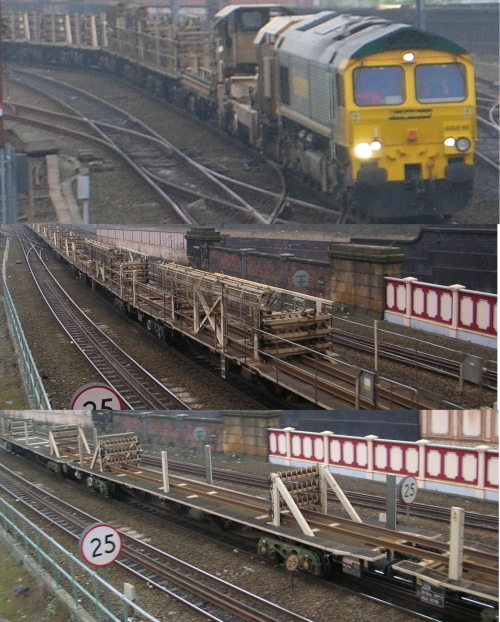
I understand that lengths of up to 230 yards
can be supplied from the steelworks these days (thanks to continuous
casting methods) but in N the rails would not bend so this is not
really an option.
Most welded rail in Britain has been welded
on-site using a special train which lifts the track, runs it over a
series of wagons where it is welded and ground smooth, then re-lays
it behind. Once welded and laid on the sleepers the rail is heated
and the securing clips banged into place, as the rail cools it tries
to shrink but it is held by the clips to the heavy sleepers. This
pre-tensioning of the track eliminates, or at least greatly reduces,
the danger of the rails expanding too much in hot weather and
buckling. In the mid to late 1990's a new technology called 'flash
butt welding' was introduced, this employs a machine able to run on
road or rail which can rapidly weld plain rail ends together very
quickly. This technology allows shorter rail lengths to be welded and
hence allows for track with fewer joints even close to points and
crossings.
Fig___ Photograph of a joint used with
welded rail
Even with the pre-tensioning allowance has to be made for
expansion in hot weather and contraction in the cold. Welded rails
therefore have special 'expansion joints'. As the lengths
of rail involved are long the cumulative expansion is large so at the
joint the ends of welded rail are cut to wedge shape and a special
chair is fitted to hold the ends together.
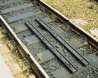
The joints are
only about eighteen inches long and quite difficult to spot, the
give-away is that two lengths of old bullhead steel rail are bolted
across the four sleepers bridging the joint, note these sleepers are
wooden even if the remainder of the track uses concrete sleepers. The
old rail is only about two-thirds the size of the running rail, but
even so it might foul the coupling pin on an N Gauge model. The best
option would be the finest rectangular I section Plastruct Fineline
(reference BFS-2) and sand the bottom sides almost flat before gluing
the two lengths in place. Welded rail has no joints in the old sense
of the term and hence eliminates the clickety-clack noises of the
older tracks.
The Liverpool & Manchester Railway of
1830 settled on fish-bellied rails some fifteen foot (4.5m) long and
each supported in seven cast iron chairs. They experimented with both
wooden sleepers and stone blocks but with the development of
effective wood preservatives they found the wooden type preferable
and this became the norm. Porous wood is used as this absorbs more
preservative (the average sleeper soaked up about three gallons of
creosote) and wooden sleepers can last up to twenty-five years in
service. Where there was a danger of fire, such as on the great
timber 'fan' viaducts built by Brunel, the wood was not soaked in
creosote but instead treated with a more expensive mercury based
liquid.
The LNWR tried iron sleepers but this was not a
success and various companies including the LNWR and GWR tried steel
sleepers, but again these did not catch on in the UK. Everyone
settled on Baltic Redwood timber sleepers, originally nine feet
(2.7m) long, reduced to about eight foot six (2.59m) with the
shortages caused by World War One. With the advent of the Second
World War, and after that the Iron Curtain, Baltic timber became
unobtainable, Canadian Douglas Fir was tried but this proved less
than ideal and interest focused on concrete sleepers.
The
earliest reference to concrete sleepers I have found was on the
distinctly different Weston, Clevedon & Portishead Light Railway
who used them from about 1909. The sleepers were unconventional in
design, rectangular concrete blocks linked by transverse iron rods
similar in appearance to the old stone block sleepers. These proved
something of a success on the WC&PLR but other companies had
little success with concrete sleepers of more conventional design as
they tended to crack in service.
The first general
introduction of concrete sleepers on main lines took place in the
late 1930's. These were of conventional design, direct replacements
for the timber type, and were fitted to carry chairs and bull-head
rail. Concrete sleepers weigh more than wooden types but last fifty
years instead of the average twenty-five for the wooden type, and
with mechanical handling (introduced due to wartime manpower
shortages) the weight was less of a problem. The problems of the
concrete cracking in use have been resolved and concrete sleepers are
now standard for plain track but to date wooden sleepers are still
used for point work. Modern practice favours the use of hardwood
sleepers as these last much longer than the soft wood types. Steel
sleepers, imported from the USA, are in place on some limited
sections of track in Britain but they are extensively used in Europe,
mainly in Switzerland. Steel sleepers are not solid blocks, they are
formed rather like an inverted pie plate with a dished under side,
this saves weight and cost and helps the sleeper bite into the
ballast. They are not ideal however as they lack weight, which is an issue when using pre-tensioned welded rail (discussed below), so they are not suitable for main lines. I have only seen steel sleepers once, stacked by the track side awaiting use. These were 'rust' coloured and had the track fixing clips built-in.
Currently (later 1980s) the railways are replacing about a million
sleepers every year, over half of which are concrete. Old wooden
railway sleepers had a ready market, used for everything from
building heavy fencing to building up flower beds in peoples gardens.
Creosote is distilled from coal tar and contains something called
benzopyrene, in 2003 new research suggested that even the trace
amounts of this material remaining in old sleepers represented a
health hazard. In 2003 the European Union sponsored legislation
banning the sale of old wooden sleepers. Network Rail is therefore
faced with a problem of what to do with them, one option being
considered being to build a special furnace that can use chipped
sleepers as fuel (examples of which are already operating on the
continent).
Railways require a stable base or track bed,
after rain the earth softens and the track becomes uneven. The
wagonways of the North East were mainly built to carry coal and ore
to the ports, the ships arrived filled with a 'ballast' of broken
stone and gravel and this was taken and used by the railways to form
a path on which the track was laid. This allows rainwater to drain
away giving a more stable surface and the term 'ballast' has remained
in use ever since to describe the broken stone path along which the
railway runs.
In the 1870's there were several derailments
caused by rails breaking, the railway companies blamed the quality of
the steel used for the rails and suggested it had been weakened by
exceptionally cold weather. The British scientist Joule decided to
experiment to test this idea. He used nails and needles for the
experiments, this was the first time someone conducted such an experiment where the materials used were scaled down and there was much debate about the validity of scaling
things down in this way. He found that the steel was actually
strengthened by cold weather, when most of the accidents had
occurred, and that the problem lay in the design of the track bed.
This lead to further experimentation by the railway companies and the
development of a standard method for ballasting track.
Fig___
Bullhead track and cross section of track bed
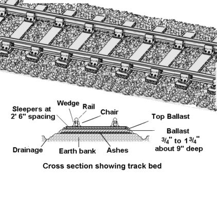
Most lines used crushed stone ballast, limestone and granite
were both common. These materials start off white but soon develop a
coating of brown or rust coloured brake dust and black sooty deposits
from the steam locomotives. Since the introduction of diesel power there has been a steady
deposit of oil along the track between the rails darkening the
ballast to almost black in stations where trains tend to loiter. From observations on my local line it has
taken three years to turn the fresh laid white ballast to a patchy
brown.
Other ballast materials were also
used, depending upon what was available locally, in Wales broken
slate was common in the North and the dark waste from lead mining was
common in the South.
Some ballast had high levels of toxic impurities
(such as the lead mine waste) which inhibited weed growth, where this
was not the case it was (and remains) necessary to treat the track
with weed-killer to prevent the plants clogging up the ballast and
reducing the drainage. Where track was laid in goods yards,
marshalling yards and industrial premises where speeds were slow and
uneven track was not such a threat a simple bed of ashes and cinders
was laid. The track in these areas was not on a raised earth bank and
this is clearly visible when you look at a yard area beside a main
line. If you are using cork strip under your track do not use this in
yard areas and paint the ballast and surrounding ground black.
On
quiet branch lines ash ballast was also sometimes used for the
running lines, although this would be laid on a conventional earth
bank to assist drainage. Ash ballast tends to allow the track to sink
deeper in than broken stone, often it crept up to the sides of the
rail and its finer appearance is relevant to the modeller. Fine sand
serves for conventional ballast, for ash something rather finer is required, I have had success with Chinchilla sand (from the pet shop). I use this for conventional broken stone ballast as well but it can be smoothed down with a wet finger after the glue has been added, producing a much flatter surface resembling ash and cinders. Ash and cinder ballast was (certainly in sidings remembered from my youth) almost black, presumably when freshly laid the ash would have added shades of lighter greys. When gluing the
finer material down using the usual syringe of diluted PVA glue I
have found it tends to contract and crack when drying so I add a thin
coating of undiluted glue over the top and sprinkle on additional
material in the affected areas.
One variation on standard
track is 'inset track', where the track is set into the surface of
road or yard area. The first use of this kind of track was in 1852
when Frenchman Emile Loubert used it for tram rails in the street.
Inset track became the norm for trams running in city streets
but it was not common on railways. A few areas in goods yards might
have inset track, and where light railway or industrial siding lines passed along public roads the track
was set into the road surface, but their main use was in industrial
locations and docks. In dock areas inset track was common but it costs more to lay and is more difficult to maintain so it was avoided where possible. As an example in the Trafford Park industrial estate in South Manchester the rail lines were all conventionally ballasted track beside the roadways, only being inset where they crossed roads.
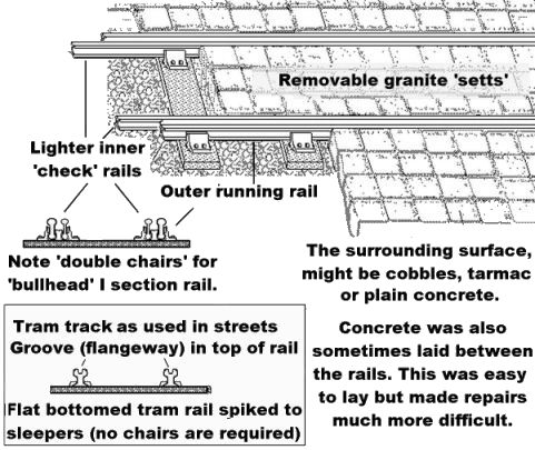
Inset track could be laid using either
pairs of standard rails (with one laid as an inner 'check rail') or
specially rolled 'tramway' rail as shown in the drawing below. Note
the 'tram' rail is actually a single rail with a groove in the top
for the flange of the wheel. This flat bottomed rail is secured
directly to the sleepers with steel spikes. Tram rails were not
suitable for railway rolling stock as the groove was too shallow (the
flange on tram wheels is much smaller than on a railway wheel).
Specially produced inset rail suitable for railway wagons was used in
some locations but as the railways had a plentiful supply of standard
bull-head rail requiring only double versions of standard chairs the
twin rail arrangement was common.
Fig___ Inset track
Where the lines handled normal railway traffic the surrounding
road or yard surface was built-up to the height of the rails and the
gap between the inner rails would then be filled using stone setts
which could be removed for track maintenance as required. The
surrounding area was generally concreted after about 1920, and after
about 1930 a top coating of tarmac was often added. From the later
1930's, particularly on dockside lines, the ground was excavated, the
track was laid, then concrete was put down to build up the level. The
disadvantage of concreting in the track in this way was that
maintenance became a lot more difficult and in goods yards it was not
uncommon to have the road surfacing built up to either side of the
track but with the sleepers exposed between the rails. This open kind
of track is much easier to model in N, especially where the lines are
curved, and short inserts can be provided where road traffic might be
expected to cross the line. The illustration below, based on a photo taken in the 1930s, shows some inset track in a goods yard, note that the point switch rails are cut and hinged, the excavated area shows how long the hinged sections were. The point lever sits in a stone block, so it will not be damaged by passing road vehicles or trip up horses, in use the lever is lifted slightly, dragged round through 180 degrees, then folded back over and into the slot. The metal drum in the rear left is a 'capstan', discussed further in the section on turntables points and slips. By the 1970s the in-fill between the rails was no longer there (the stone road surface outside the rails was still in place) and more conventional points were in use in this yard although the capstans remained in place until closure in 1975.
Fig___ Inset track in a goods yard, note the design of the point blades
Inner 'check rails' were also
fitted to normal track where curves were tight as they helped prevent
derailments. They were first used as far back as 1729 on a horse
operated wagonway in County Durham and they were used on the steam
hauled railways wherever the curves were less than about six hundred
foot (183m) radius. That is equivalent to over four foot radius in N,
or 1.2m, which gives some idea of how tight model railway curves tend
to be. Check rails are still seen today on tight curves, note that
the check rails are only laid with the inner rail on the curve.
Abroad many railways settled on flat bottomed rails (Vignoles
section rail) spiked directly to wooden sleepers, this meant that the
heavy cast iron chairs were not required which saved on transport
costs. In the event however it was found that it was necessary to add
a steel base plate to the wooden sleepers to carry the rail.
In 1949 British Railways changed to using flat-bottomed
Vignoles section rails. The rails were spiked to wooden sleepers or
bolted down to concrete sleepers with special clamps but in 1957 a
Norwegian engineer invented the Pandrol clip. This uses a simple flat
plate with cast-in loops, the Vignoles section (flat bottomed) rail
is laid in the chair and a twist of metal, the clip itself, is
hammered into the loops to hold the rail in place.
Fig___
Flat bottomed rail and Pandrol Clips
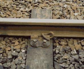
The Pandrol clip
tightens under vibration, which prevents the problem of trains
dragging the track along when the brakes are applied. Pandrol clips
save a lot of time and effort, the clips can be hammered in by a man
with a big hammer or by a rail-mounted machine, they are now in use
in over sixty countries. Pandrol clips appeared in the UK in 1959 and
they are now the standard rail fixing throughout Europe and in many
other parts of the world. The latest (late 1990's) designs of Pandrol clip use a
flatter profile.
In the 1980's a new system called paved
concrete track (commonly abbreviated to PACT) came into play. This
uses a continuous ribbon of concrete onto which the rails are usually
secured using Pandrol type clips. PACT track is widely used in
railway tunnels and for 'rapid transit' passenger rail systems and
the Japanese have used it for their new high speed lines.
In
1998 the European Union arrived at a basic understanding on a set of
international standards for track. This agreement covers the rails,
sleepers, design of points or turnouts and crossings and the method
of securing the rail to the sleepers. The Pandrol clip is the
standard fixing, Pandrol are now a British based company but supply
most of the European railways.
Noise pollution is nowadays an issue and there is a Europe wide initiative to
reduce the noise and vibration cause by passing trains. There were
three separate lines of enquiry; Silent Freight (looking at ways to
make freight vehicles quieter), Silent Track (looking at ways to make
the track quieter) and Eurosabot (developing reliable methodology for
designing tread brake blocks that would result in smoother wheel
rolling surfaces). The European Rail Research Institute (ERRI) in the
Netherlands is the co-ordinating body and the research has covered
the shape of the rail, the use of rubber pads between the rail and
sleeper, the wheel profile, modified bogies fitted with 'noise
guards' and the materials used to make the brake shoes used with
'clasp brakes' still fitted to much of the goods stock. Of these
modifications to the wheels, track and brake blocks produced the
least improvement and interest has focused on damping the wheel
vibration and developing the bogie shrouds. It is believed that a
noise reduction of up to 50 percent is possible.
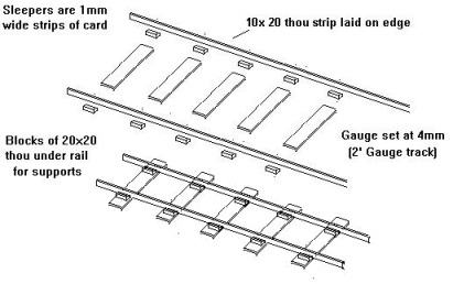
Prefabricated
(portable) Track
In the late nineteenth century an
all-metal prefabricated track was developed for light lines in
quarries and the like. Called Jubilee track it was supplied in
straights and curves with pre-fabricated point units and lasted in
use into the 1940's. The rails were held quite high on Jubilee track,
with daylight often visible beneath them when in use. Jubilee track
can be modelled as shown in Fig___ above using strips of 10x20 thou
strip (laid on edge) with sleepers of 10 or 20 thou 1mm (40 thou)
wide. I would suggest using a simple jig to get the sleeper spacing
constant as this is very noticeable when the track is stacked in the
wagon. Ideally you should add 'feet' under the track to raise it
clear of the sleepers. 1mm lengths of 20x20 thou strip would serve
well, but this would be fiddly and may stretch your patience.
Fig___ Modelling Jubilee Track
On
the horse operated tramways a smaller version of Birkinshaw's rail
was sometimes used in the form of short lengths bolted down to stone
or wooden sleepers. This type of rail was not as common as the L
shaped or fish belly type on these wagonways but it has the
advantage of being much easier to model. Having made two lengths of
track as shown in Fig___ above you then need to draw the line of the
rails onto the baseboard, light railways using this kind of track
ranged from two foot to four foot gauge. Next glue the lines of rail
in place over your drawn lines, making the necessary 'dog-legs' at
the 'joints' and when these have set add a thin coating of fine sand
to represent the ballast. The ballast could be white (limestone or
granite), black (cinders or lead ore), or grey (slate) depending on
what was available cheaply in the area. Add some weeds from teased
out (used) pan scourer between and to either side of the rails and
build up the ground cover along the line.
^
Go to top of page
International Good Guys ~Queuing, patiently, since 1971 ~ Site maintained by

All material Copyright © Mike Smith 2003 unless otherwise credited