Modern Waste Disposal Services
During the later 1970s and ewarly 1980's, following the creation of the new large councils such as Greater Manchester and Avon (centred on Bristol), money was put into large, often rail-connected, centralised processing plants. Major centres were established at Manchester (Northenden and Pendlebury), London and Bristol. The original plan was to shred the waste to produce something akin to compost, shredding the waste accelerates the biodegradation of the material and also reduces its volume. Over the years new technologies have evolved enabling the plant to remove and separate aluminium and ferrous (iron and steel) containers from domestic refuse and by the late 1990's plant should be operating to produce a compost-like material which will be used for forestry (it cannot be used on vegetables as it may contain tiny fragments of glass). The objective is to recycle roughly fifty percent of the waste produced, amounting to something like a kilogram (2.2lbs) per person per day, leaving a similar amount to be burned or buried in land-fill sites around the country. Land fill is cheap but the number of available locations is reducing all the time as old quarries, clay pits and the like are being filled faster than the new sites are opened. As a result incineration in specially designed high temperature furnaces, possibly with power generation as a by-product, looks likely to feature in the longer term waste management strategy.
The existing plants mainly shred the waste as incineration is for the moment less cost effective than land-fill. A typical site would comprise a large shed structure housing the processing equipment, an office, a weigh bridge for commercial rubbish brought in by road and usually a site for local residents to deposit their larger rubbish. There will be a couple of lockable store rooms, usually with open mesh fronts, to hold old batteries and the like (these are often painted red) and a range of specialised vehicles used in handling the material.
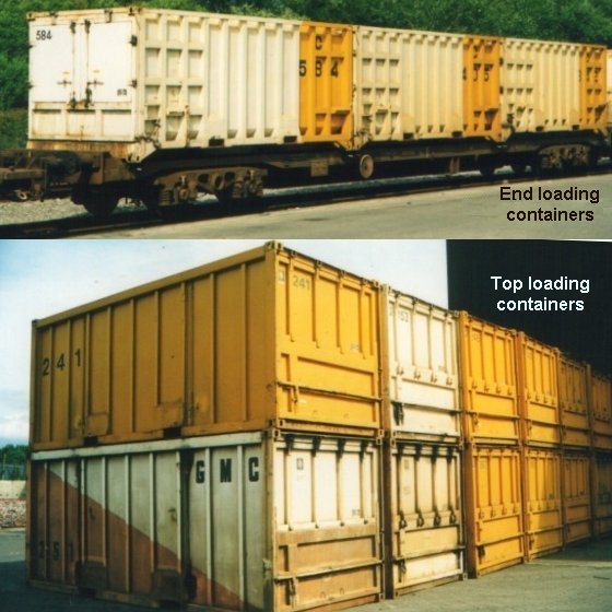
The Northenden rail connected site uses two types of heavily ribbed containers to shift the compacted waste, one is top-loaded through two rooftop hatches, the other is loaded by ram through end doors of conventional appearance. The two types can be distinguished by the pattern of ribbing on the sides, the top loaders having plain vertical ribs whilst the end door types have additional horizontal ribbing at the ends. The containers are handled by large fork lift machines, they are placed in turn in bays in the side of the main building for filling, then moved onto the waiting railway container flat wagons. The wagons used resemble freightliner wagons but they are owned by the local authority which operates the site. A typical train load runs to about fifteen wagons, each with three containers, on average there are about twice as many end-door containers as top loaders.
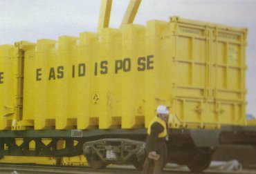
Prototype Easidispose container
The trains use Freightliner type flat wagons but the container flat wagons are all privately owned or leased. London, Greater Manchester and Bristol (Avon Metropolitan) all operated such systems at the present (mid 1980s), and other towns are considering the idea. Although resembling Freightliner trains, being `block trains of containers on flats', these waste movement operations fell under the control of Railfreight Construction sector.
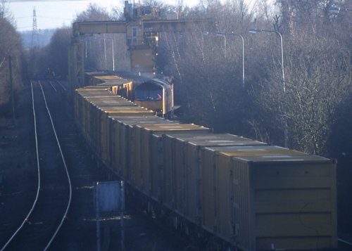
Fig ___ Photos taken in later 1980s of a Manchester 'binliner' flat and containers.
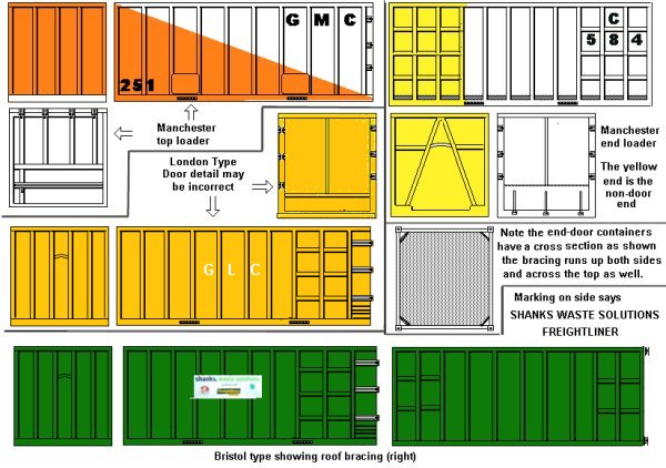
The 'easidispose' containers used on the prototype operations have distinctive external ribbing, these can be made up using 1" PAR strip wood planed down to 15mm square with ribbing added from thick card (of the type used to back writing pads), making a mould and banging them out using plastic padding would be an option. The Greater Manchester examples were initially painted in the county colours (pale cream and an indescribable orange, the result of a competition amongst school children I believe), with GMC painted in black towards the upper left in letters about 12 inches (30 cm) high. The London based containers were yellow with GLC either centrally on the side of the container, or in a vertical line (G at the top) in the last bay on the side. In the early 1990's there were still a large number of waste containers in these original liveries but following experiments with a white and yellow scheme Manchester at least opted for all yellow with black lettering, the white and yellow then came in again following the wind up of the metropolitan borough councils. In 2006 there were still containers in all three GMC liveries at the Northenden terminal but I believe only the yellow and white were in operation. The end loading Manchester type is shown below on the right, the London type has three horizontal bars on the sides at the door end only and the non-barred end has three horizontal bars across it, on these (which are end loading) the frame continues across the top of the container.
Fig ___ Sketches of 'Binliner' containers.
Loading Facilities
The Northenden terminal is situated at the junction with the line to the Peak District used by the ICI limestone train running to the Brunner Mond (formerly ICI Mond Division) plant in Cheshire. There is a gate at the rail entrance but I have never seen this closed.
Fig ___ Sketch showing location of the Northenden terminal.
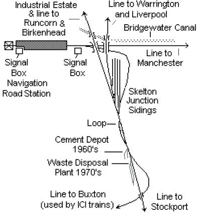
Fig ___ Photo showing entrance to Northenden terminal.
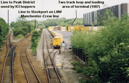
The Northenden terminal consists of a large building with various doors but no windows fronted by a hard standing area then a loop of two tracks feeding a head shunt. This would be an easy site to model, although making the large number of containers would be tedious.
Fig ___ Photos of the Northenden terminal.
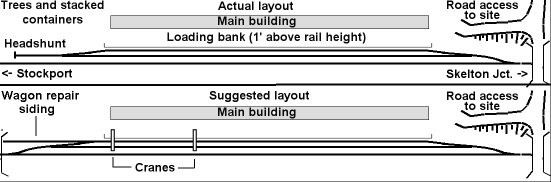
The main building, modelled in low relief, would need to be about an inch deep, the hard standing would need to be about three inches deep and the two tracks would require a further three and a half inches. Adding the 'main line' requires at least two inches (for a single track) so the front-to-back depth would need to be in the region of 10 inches. You would need a loop about three feet long (capable of holding six flat wagons), with another foot for the headshunt and about fifteen inches for the connection to the main line, so you should probably allow about six feet in length. This could serve as the front to a hidden fiddle yard area on the layout.
I have on occasion seen rakes of wagons on both the sidings at Northenden but usually only a single rake is on site at any one time. Trains of empty containers arrive from the Stockport direction and are reversed into the inner siding, the loco then goes light engine to a depot. A light engine is sent from the depot to collect the full rake, entering on the outer siding to reach the far end of the rake, reversing this out then proceeding in the Stockport direction to the main line. This fits well with a model railway as there is likely to be a depot to take the light engine movements.
Having one engine deliver the empties and collect the full containers in a single movement is problematic. On the prototype there is a loop on the line that can be used for a run-round, so the empties can be deposited in the outer siding, the full containers can be taken to the loop and the empties can then be shunted into the inner siding.
Adding an overhead crane (as is used at the Bristol terminal) would make life easier as this would allow the outer siding to be used for loading and unloading the containers. Having a point on the main line at the Stockport end of the loop would make life much easier as this would allow the main line to be used to run round both sidings. On the prototype the shunting of this terminal blocks the main line, so that would to some extent be prototypical. Adding a spur siding to the loop can add some operational interest, it could be used for a wagon repair service, or to load vans with compressed blocks of recovered aluminium (these are about three feet cube). The van siding could be at either end of the loop, positioning it at the entrance end would allow it to curve across the front of the building.
Fig ___ Suggested track plan for a Northenden type terminal.
The Bristol type terminal requires less depth to model, however I have not established the prototype track plan. As shown in the sketch the containers are shifted using travelling cranes, supported on the building end by a rail on the edge of the roof and at the outboard end by a mast running on a wheeled base. Containers can be laid beside the siding but there a set of end-loading points on the side of the building so the cranes have to rotate the boxes to offer them up to the loading points. The front to back depth for the layout as shown below would be about 7 inches.
Fig ___ Suggested track plan for a Bristol type terminal.
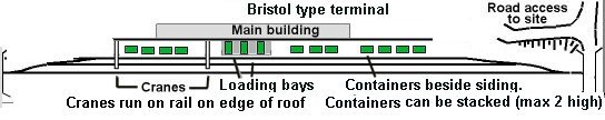
The raised rail continues beyond the end of the building, this is easy enough to model using Plastruct I section supported on XXXX OO scale 'modern electric light' masts, the lower web of the I beam should be cut away where the mast is attached. Along the top of the main I beam a much smaller Plastruct I beam represents the running rail.
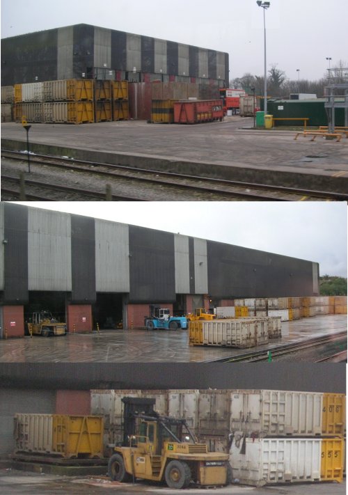
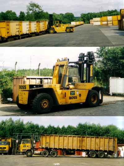
The photos below, taken in the later 1980s, show (top) a fork lift collecting a container from the train, (middle) a typical fork lift as used on the site and (bottom) one of the large ribbed-body road trailers that access the site (I have no idea what they carry, but they look impressive).
Fig ___ Photos of the Northenden Terminal in the later 1980s
Discharging Facilities
Modelling the reception facilities is an alternative approach, the example shown in the photos below (Calvert in Buckinghamshire) takes the waste from the Bristol and Bath terminals and also receives railway spoil in open wagons, adding some variety to the operations at the site. This requires an 'earth bank' (hiding the tip itself), a roadway about two inches deep, spanned by the 'Goliath' type traveling crane (there are two actual cranes on the example shown), with two sidings and the main line, giving a total of about 10 inches depth and a length of roughly six feet. Again this would be suitable for fronting a hidden fiddle yard although the 'earth bank' would not be as high as the building of the Northenden terminal.
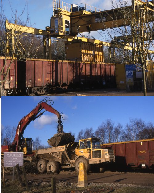
Particular thanks are due to Guy Gorton, a regular on the uk.railway newsgroup, for allowing the use of photographs he took of the reception facilities for waste disposal trains in Buckinghamshire. The photos below show the entrance to the terminal, the unloading of waste containers and the unloading of spoil from the building of the Channel Tunnel Rail Link in late 2005. Guy does not currently operate a web site but the original pictures may still be available at http://www.meadwaypark.co.uk/. Guy describes this as 'Not really a proper website, just some images that might appeal to some with a historical interest.'
Fig ___ Photo of the rail entrance to the Calvert, Buckinghamshire, terminal.
The containers are transported on vehicles similar to the spoil truck but with a tipping flat-bed tipping at the rear in place of the earth bucket.
Fig ___ Photos of a container and railway spoil being unloaded at the Buckinghamshire terminal.
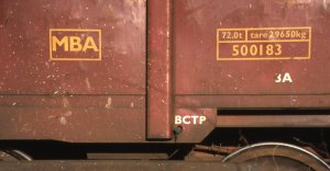
Guy also supplied a close up showing the markings on the MBA spoil wagons being used at the time.
Fig ___ Photos of marking on an MBA spoil wagon.
The Manchester 'binliners' run to a terminal at Roxby Gullet, an former ironstone quarry adjacent to the northern extension of the Lincoln Edge. I have not yet found any reference sources detailing the operations at this site. The London binliners from Cricklewood used to go to the landfill site at Forders Sidings, on the Bedford to Bletchley line. This was declared full in (I think) 2004 and services now go to Calvert. The Calvert site was once owned by the London Brick Company and only ceased producing bricks in the later 1990s, after the landfill operation had been running for several years. In 1893 an incinerator (they called it a 'destructor') was built at Powderhall waste transfer centre in Edinburgh, from this terminal a binliner service operates, however I do not have any further information on this traffic.
Waste trains fell under the Construction sector in the final years of BR, then following privatisation EWS hauled all the waste trains until 2000 when Freightliner won the contract for the Bristol and Bath terminals.
____________________________________________
^
Go to top of page