Mines and Quarries - Introduction
For several thousand years Britain's wealth was built on mining, up to the early 1980s there were many thousands of people employed in mining and quarrying across the country. Coal was the main material mined, providing fuel for homes and power stations and producing gas at the gas works and the Cambourne school of mines in Cornwall was the recognised world leader in training. Mining provided one of the primary drives for the development of the railways and mined materials remained an important cargo for the railways into the 1990s. In the 1980s the government decided that the established 'heavy industries' (mining, iron and steel production, shipbuilding and shipping, all of which required skilled people who had received expensive training) should be wound up. Those parts of the industries involved that had been nationalised were sold off and a programme of large scale closures was instituted, although there were numerous strikes by the workers protesting this policy. By the early twentieth century (I am told) there were about five hundred people employed in the mining and quarrying industries across the country, indeed referring to it as an industry is perhaps something of an over statement.
The dominance of the coal industry was a product of the industrial revolution and the development of steam power for the mills, factories and railways. Britain was known in the ancient world as the 'Cassiterides' or 'tin islands'. The earliest known mine in the UK is a flint mine at Church Hill, Findon, West Sussex, dating to around 3390BC. In the 1840's Britain was producing seventy five percent of the worlds copper, sixty percent of the worlds tin and over fifty percent of the worlds lead. Copper was mined in Anglesey, Devon Cornwall and Ireland, tin was mined in Devon and Cornwall whilst lead was mined in the Peak District (on the border of Yorkshire and Derbyshire), in Wales, Ireland and the Isle of Man. Zinc and other minerals were also worked, often mines dug for one material also produced other useful products, for example silver and zinc were often produced at lead mines.
Prior to the massive growth in coal mining there were many small mines dotted about the place, in the heart of the Cheshire farm lands there was a copper mine dating back to pre-medieval times on a volcanic outcrop called Alderley Edge but Cornwall is really the home of the British mining industry. Cornwall has always had a problem growing enough food for its people so even in the Middle Ages the mining of minerals was an important trade. The geology of the south western peninsular (Cornwall and Devon) is amongst the most complex in the country, tin, copper, lead, zinc, antimony, arsenic, cobalt, wolfram, manganese, bismuth, uranium and kaolin (China clay) have all been commercially mined there. Tin and copper were the most valuable and laws were made to free the Cornish tin miners from the normal feudal duties to allow them to produce more. By the eighteenth century the surface tin had been virtually worked out and mines had to be sunk which changed the character of the industry completely as capital was then required. In the 1870's the tin mines began to close and there was a large scale migration of miners from Cornwall, many of whom took their skills and some of their technical terms abroad.
Coal and iron ore are the most important mined materials from the point of railway involvement, other materials mined, that is recovered from underground using tunneling methods, include metals such as copper, lead, zinc and tin and stone, such as granite (for hearth stones), flint and chalk. Even clay has been mined (for brick making) and there are a whole range of less common minerals such as fluorspar (natural calcium fluoride CaF2) which is common in Derbyshire. Better known as 'Blue John' this mineral comes in a range of colours, yellow, green, bule or purple with white streaks, it is used to make hydrofluric acid, refrigerants, enamels, in the manufacture of non-stick pans and glass. In the period before the Second World War it was mined at Eyam and loaded into rail wagons at Grindleford on the (LMS) Hope Valley line over the Pennines.
Fig ___ Types of mine & mining terms
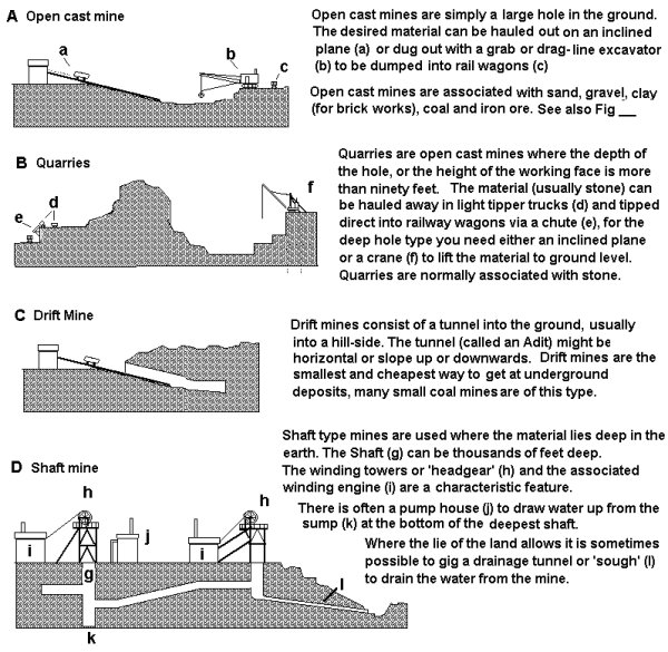
In open cast mines (Fig ___ A) and quarries (Fig ___ B) where soil or rock has to be removed to get at the desired material this is called 'overburden'. Open cast mines are easy and cheap to operate but they can do great damage to the landscape, this became a serious problem in the 1890's as the steam shovel came into use. In the later 1920's and 1930's open cast mining was applied to a much larger range of minerals and appeared in most mining areas of the country. During this era the steam powered excavators increased in size dramatically and the damage done to the land increased in proportion. In the 1950's legislation was passed requiring the fertile top-soil to be removed and stored so that when a worked-out part of the pit was filled with spoil from new working it could be covered with top soil and the land restored to productive use.
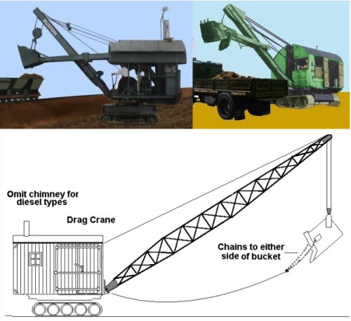
Fig ___ Steam excavator, diesel excavator and drag crane
A variant on the open cast mine is the 'strip mine', the word 'strip' does not imply that the land is stripped (although it used to as noted above), the strip is a long trench cut in the earth to access the required material. Large cranes remove the overburden which is piled up to one side and the ore or coal is removed. Next a new trench is dug alongside the first, the overburden from the new cut being used to fill-in the first. In this way the mine forms a strip which moves sideways across the landscape. See also 'Mining and smelting Iron Ore and other metals'.
Technically a quarry is an open cast mine which is more than ninety feet deep. Usually where stone is being recovered the mine is called a quarry regardless of its type.
Early mining consisted mainly of gathering materials where they formed outcrops on the surface, very often the bed or seam of the desired material dipped down into the ground and could be followed by tunneling (Fig ___ C). Generally if the tunnel angles downwards into the ground it is called a 'drift', if it angles upwards it is called an 'adit' (and also serves to drain water) but all mines of this simple type are called 'drift mines'. Drift mines are usually driven into the side of a hill. They were common in the coal fields but they were also used for quarrying stone where the bed inclined steeply down into the ground. This approach saved removing a large quantity of 'over burden' to get at the rock and was used for all types of stone quarried.
In a drift mine the tubs of mineral are pushed along light plate ways by hand or hauled to the surface by horses or by a petrol, diesel, steam, electric or pneumatic powered cable system. Horses were used in the larger mines into the 1960's and continued in use in the small independent mines into the 1990's.
The third type of mine is the shaft type (Fig ___ D) where a vertical shaft anything from six to fifteen foot across was dug down into the earth to reach the wanted material. A system of cables is used to lower men, horses and equipment down and bring up the material being mined.
Early miners used baskets to haul the minerals up the shaft but by the 1830's cages running in shafts fitted with iron guide rails had appeared. By the 1840's mine shafts were taken down anything up to a couple of thousand feet and there were problems showing up with the hemp rope used for lifting the loaded cages. By the end of the eighteenth century wrought iron chains were being used at some mines but these were heavy for the weight they could carry and failure was usually without any warning.
Miners in Germany began using a new cable made of iron wire in the 1830's and a trial in Durham in the 1840's convinced the British mining industry to change to iron wire rope. Today steel rope is used but despite the value in the metal the winding ropes from collieries and other deep mines are not sold for scrap, they have so much stress wound into them they cannot be safely cut and have to be buried and allowed to rot slowly.
To allow efficient ventilation even a small shaft type mine should have two shafts, the 1862 Coal Mines Act required collieries have two shafts which connected to all working levels separated by not more than fifteen yards apart. In practice there were also out-lying shafts, sunk for ventilation or (more likely) to reduce the underground haulage of coal, which often had only a single pit-head winding tower.
Although ventilation was the prime concern all shafts would usually be equipped with winding gear in case of emergencies. In some mines a drift entrance was used to bring the coal or ore to the surface in tubs or on a conveyor belt whilst a shaft provided ventilation and possibly access. Often the drift and shaft entrances were relatively close together but as the seam was mined away a new shaft might be sunk closer to the coal face. The old shafts were sometimes retained, used for access or ventilation, and some mines had as many as seven shafts dug as the work progressed along the seam.
In the days before mechanical fans were efficient and economical common practice was to light a fire under one of the shafts to generate a draft and draw air in through the second entrance. The dangers of methane explosion in coal mines meant that steam driven fans, usually located inside the mine at the bottom of the shaft, were installed as the technology developed in the 1850's. Open fires for ventilation remained in use however, they were finally banned by the Coal Mines Act of 1911. This Act also banned smoking tobacco in mines, and cigarettes, pipes and above all matches were classed as 'contraband'. Anyone found in possession of same in a mine was liable to both instant dismissal and prosecution. A notice to this effect is even today always posted by the entrance to a mine, regardless of its size. Chewing tobacco and snuff (powdered dried tobacco) were both popular, and advertisements for Red Man or other brands would be seen in mining areas.
Being holes in the ground mines were prone to flooding but here the lie of the land allowed them to dig drainage tunnels called 'soughs'. Soughs could of course only be used in hilly areas and they were expensive and difficult to build but there were potential advantages to the system. For one thing the sough could be widened sufficiently to take boats, the Duke of Bridgewater used this idea in his Worsely mines to allow coal boats from his canal to travel into the mine workings. Another possible benefit was that the water pouring from the sough could be sold, sough water does not stop during the winter freeze and in limestone areas the quantity of water delivered is often considerable. Sir Richard Awkright used water wheels to power his first cotton factory and the location was chosen because there was a steady water supply from a sough. Even today a lot of sough water is drawn off by the water companies for the domestic supplies.
The development of steam engines is closely related to the mining of coal, in part because the early engines were highly inefficient and only suitable for use where coal was plentiful and cheap. Steam power was initially used for pumping water out of the mine workings, Cornwall was a major mining area and lacking many rivers for power it was also the home of the early steam engine industry. The tall 'Cornish' pump house was used in many areas up to the early twentieth century (one was built at a coal mine in Cheshire in 1900 which continued working into the 1930's).
Fig ___ 'Cornish' pump house
For hoisting cages in early shaft type mines horses were used but as mines became deeper water-wheel driven hoists were developed Early steam powered hoisting systems actually used steam power to pump water to supply reservoirs which then supplied water wheels. By the 1840's high pressure high speed steam engines had developed and were driving the winding drums directly.
Not all shaft type mines were as large and impressive as those shown in Fig ___ above, lead mines in Derbyshire for example seldom had large towers at the pit head. Often in the lead mines (and in quite a few very early steam powered mines) a single engine house was used to wind several shafts, the ropes running in pulley wheels about a foot (30cm) in diameter, mounted in six foot high posts trailing across the landscape.
Electric power was slow to appear in mines, there was an electrically powered coal cutting machine tried in 1885 but other than for lighting and signalling up and down the shaft electricity was little used inside the mines until the 1940's. Many larger collieries built their own power stations for supplying electrical power but most favoured direct current supplies produced by steam powered dynamos. As the power did not have to be sent any great distance there was no advantage to alternating current supplies and DC supplies offer several advantages in controlling large motors. Electric hoisting engines began to appear in some numbers from the 1920's, interest being concentrated in South Wales, Durham and Northumberland. Steam remained common for many years however, by 1900 depths of a couple of thousand feet were regularly hauled at speeds of up to thirty odd feet per second using four cylinder compound steam engines. This was as fast as the best electric winding systems and steam remained in use into the early 1980's.
Compressed air motors were used in collieries from the late 1840's, mainly in connection with mechanical coal hewing machines but mechanical coal recovery did not become really practical until the 1890's.
From a railway modelling point of view there are two parts to a mine, the hole in the ground where the material is extracted and the works on the surface where the valuable material is separated from the rock and earth that inevitably comes with the wanted material. The nature of the surface work depended on the material being mined, coal mines had buildings for washing and grading the coal, iron and other metal ore mines had stone crushers to break the ore down and usually some method to separate the ore from the rubble.
Rock can be broken by men using large sledge hammers, and up to the mid nineteenth century convicts were often sentenced to 'hard labour' which usually meant breaking up rock with hammers. Where convict labour was not available doing this work by hand was not economic. Up to the mid nineteenth century the large scale crushing of stone and ores was usually accomplished using heavy stone wheels mounted close together on an axle which in turn was attached to a vertical post. The vertical post was powered by a water wheel, causing the two wheels to roll round in circles on a stone bed. This required the quarried stone to be transported to the crushing mill which commonly involved tramway wagons of some form.
Steam powered 'jaw crushers' were invented in America in 1858 by Eli Blake (the cousin of the man who invented the cotton gin). They appeared in Britain in the 1860's when Marsden's of Leeds obtained the licence to build them. In the jaw crusher the jaws operate rather like those on a set of heavy pliers. The opening end faces upwards and lower end of the jaws are set to the required distance apart to produce the desired size of rubble.
Early models could process in the region of twenty tons of stone a day and in a large quarry several of these might be set up in a row, powered by one or more portable steam engines. These jaw crushers were comparatively small machine which could (with difficulty) be moved about the quarry as required.
For really fine crushing, required by some metal ores, the rock could be placed inside a rotating steel drum in which a couple of heavy steel balls roll about breaking the rock down. Ball mills of this type can reduce rock to a powder.
Naturally the broken rock created by any of the above methods included a variation in size (although the jaw crushers were generally quite good at producing standard sizes). The next problem is sorting the different sizes into piles and this is usually done using something called a 'screen' or 'grader'.
Screens came in various forms, the simplest I know of was used at gravel pits and consisted of a set of iron or steel bars arranged on an incline. The gravel was dumped on to the top of the bars the larger pieces rolled down to the end whilst the small pieces fell through. A larger and more sophisticated version might have the bars arranged with widening gaps between them, in which case as the material rolled down progressively larger pieces would fall through to form a series of graded piles.
For larger installations the most common type consisted of a series of inclined steel plates punched with holes, often the plates were attached to a vibrating mechanism. The holes were smaller on successive plates to separate the broken rock into sizes and any lumps which were still too large passed right over the screens and could be fed back in to the crusher. This arrangement was common in coal mines but was obviously not portable.
Vibrating the heavy steel plates brings with it problems of reliability and an alternative approach is the trommel or riddle. A trommel is a rotating metal tube mounted at an angle and with holes of increasing size punched along its length. The crushed rock was fed into the trommel and rolled down, falling through the holes. The different sized holes, of increasing diameter along the tube, allowed material to fall though as it passed down the tube with the smallest bits falling through first. Trommels came in all sizes from small 'portable' units used in quarries to very large units used in coking plants and gas works. In the quarry it made sense to add a trommel to the stone crusher to form a single unit powered by a single steam or oil engine.
Fig ___ Small 'jaws' stone crusher and trommel (1860's-1930's)
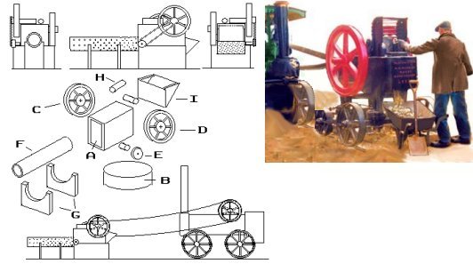
The main body of the unit (A) can be any rectangular section material, solid or tubular, about 6mm wide, 10mm long and 8-10mm high. This sits on a base (B) which is about 6mm high, roughly the same length as the main box but slightly wider. One one side of the main box is the drive wheel (C), this carries the drive belt from the mobile engine. On the other side and mounted at the top is the heavy fly-wheel (D), both these wheels can be represented by small press-studs.
On the same side as the fly-wheel is a smaller wheel (E) which is linked to the centre of the fly-wheel by a belt and operates the 'trommel' (F). To represent the trommel a length of old 'Biro' tube about 15mm long would serve, paint this black with some light grey dry-brushed on. When dry add black dots with a fibre-tipped pen to represent the holes. Any pieces too big to pass through the holes fell out of the far end and were shovelled back into the feed hopper for another run. The two supports for the trommel (G) are solid walls as they serve to keep the rubble divided by size as it falls from the holes. These can be made up from 20 thou card easily enough. A couple of lengths of 2mm rod or similar are glued to the top of the main box to represent the 'works' (H) and a simple hopper (I), made from paper or plastic card is added to the rear.
These machines were usually in the open, perhaps covered by a simple wooden frame with a sloping corrugated iron roof. They were usually arranged to be at a higher level with chutes down which the rubble can be shovelled into quarry wagons or directly into railway wagons.
The recovery of witherite ore provides a good overview of the surface processing at a typical mineral. Witherite is a Barium compound usually found in lead mines although seldom in worthwhile quantities. It was named after Doctor Withering who, in 1764, discovered it was not chemically the same as Barytes. It is one of the few minerals for which the UK remains the worlds principal supplier (at least in the early 1980's that is) and it is quite valuable with uses including putting a high gloss glaze on paper and making explosives. I know of only two Witherite mines, a former coal mine at Annfield Plains near Durham and a former lead mine at Settlingstones close by Hadrian's Wall. The latter was described in an article in the Autumn 1987 'Industrial Heritage' magazine, published by the Yorkshire Dales Railway Museum Trust who are based at Embsay station, Skipton. The Settlingstones mine closed in the 1970's, by which time the daily output of ore was in the region of thirty tons.
Fig ___Witherite Mine
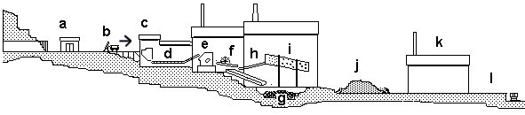
The ore was mined by blasting, so the occasional gunpowder van would be justified and a suitable building would be needed for the 'magazine' (gunpowder store). This would be quite small, about the size of a large garden shed, windowless and solidly built (Fig ___ a). Gunpowder was first used in mining in about 1660,
The mine was a shaft type, but a drift type would be fine for a model (this saves you having to make the winding gear). The rubble was lifted up the main shaft in half ton wheeled tubs and hand-trammed (pushed) to the crushing mill located close by (b). By the 1850's most mines used malleable iron 'edge rail' systems along which men or ponies pulled the loaded tubs. Modelling the tubs is discussed in the section on 'Kit Bashing'. In this case the track was edge rail, laid on wooden sleepers, but a plateway or fish-belly type of track could be used. Modelling these alternative tracks is discussed under Track & Gauge.
One problem faced by all mines was sorting the desired mineral from the rock and general detritus, this was more of a problem in some mines than in others due to the intermingling of the seam with other material. The technical term for the unwanted material is 'gangue'. People were employed to pick out the larger bits of rock and from about the 1860's rotating tables and simple conveyor belts made from old winding ropes were provided to help them in their work. This requirement for picking out the rubble is one reason why mines favoured smaller sized tub wagons rather than large buckets for lifting the coal up the shaft. Incidentally the wheeled tubs were called 'hutches' in Scotland and 'drams' in Wales, at least in the coal mines.
At the crushing mill the rubble was tipped into a hopper (c) feeding a picking belt (d) where staff removed the stone and general waste. The ore then passed into the crusher (e) where it was broken down into lumps no larger than a half-brick. At the Witherite mine quite a large jaw-type crusher was used, housed in a two-storey building.
The picking stage still left earth, sand and other dregs mixed with the required mineral and water was often used to separate these materials. The original approach was to mix the crushed ore with water and allow it to flow slowly down hill in a 'buddle', the desired material either settled to the bottom (in the case of lead for example) or was carried on as the unwanted material settled (this is what is done with china clay). A development of the buddle, that became viable in the later 18th century as steam power became cheap enough to use, was the 'jigging table' so named as it was made to 'jig' rapidly up and down. In the case of metal ores water was poured onto the 'jigging table' where the heavy ore rolled across the table whilst a sideways flow of water washed away the unwanted material or 'gangue'.
Some materials such as coal will float on water so in coal mines they had a 'washery' which employed a bath, often fitted with water jets or high pressure hoses, the coal floated through and the unwanted gangue sank. Something similar can be done with air, the air flow is arranged so that the lighter material is carried upwards whilst the heavy material sinks. Coal mines used compressed air in this way to separate out the coal dust, which could be sold separately to certain industries, notably cement manufacture and electricity generation. Where this was done a common method was to use a large silk bag supported above the railway loading tracks rather in the manner of a vacuum cleaner bag. When required the dust was then simply emptied into opean wagons, which would be sheeted before shipment. To recover really fine dust another option is to mix chemicals with the water which bind to the desired mineral and also form a froth which floats to the surface, this was quite commonly done with metallic ores as described below.
At the Witherite mine crushed ore was passed to a jigging table (f) and the waste slime was passed to a dump site (g). When dealing with ore from the old lead mine the waste slime from this process often contained the lead ore galena which was sometimes worth recovering for sale. The witherite ore recovered from the jigging tables was fed onto an elevator (h) which carried the material up to a set of 'screens' (i) which separated the rubble by size.
The witherite ore was placed on a stockpile (j) outside the building containing the crusher and screens, a bagging plant (k) was located a short distance away and lorries shifted the ore to the plant for bagging although bulk supplies were also sold.
As sidelines the mine at Settlingstones sold off any galena it recovered and the broken stone excavated from the mine was sold for road building. For the present purposes I have included a wharf for loading railway wagons (l) although this was not a feature of the Settlingstones mine.
The buildings required for such an operation would therefore occupy a fair size plot of ground. A steam engine would be likely to drive the stone crushing machine and the vibrating screens, electricity might possibly have arrived sometime after the 1930's but the old steam engine itself might still be in situ. Water is required for the jigging tables, in the above case it was drawn from a nearby stream and carried to the works on an elevated wooden aqueduct supported on wooden trestles.
Not all mines and quarries were directly rail connected, in many cases it is easier to take the goods to a siding on a nearby line rather than lay in a private link. Two British 'remote' loading hoppers associated with crushed stone are illustrated in Fig ___ and a hopper-loading arrangement based on the massive Merehead stone terminal is illustrated in Fig ___.
The American book 'Modelling the Clinchfield in N' (see Bibliography) has several pictures of remote wagon loading hoppers which could be used in a British setting. Remote mineral hoppers, handling coal, crushed stone or ores, can be supplied from the mine or quarry by conveyor belts, road vehicles or by railway trucks (standard or narrow gauge).
The sketch below (Fig ___) shows several alternative remote loading arrangements. Some mines and quite a few quarries hauled the coal, ore or stone along a light 'plate-way' to the railway. The goods could then be transferred into railway wagons either using a simple loading chute or for stone blocks using a crude but solidly built crane. The sketch below shows a timber 'scotch derrick on a loading bank in the Forest of Dean used to transfer large stone blocks from plate-way wagons to the railway proper (A). Also shown is a simple wooden chute, again taken from an example in the Forest of Dean, and used up to the late 30's for the coal from a small mine father away (B). There was an essentially similar arrangement, equipped with a side tipping platform on an edge-rail two foot gauge line at a remote Welsh drift mine in the early 1990's The platform was tipped using an air-driven motor supplied by a nearby compressor.
In some cases the transport from the mine or quarry was by road, either using a horse and cart or, after the 1920's a steam or motor lorry. In this case a simple loading bank was required so the road transport could tip directly into railway wagons (C). Do note however that the height of the platform needs to be greater than for a passenger platform, if using Peco platform edging I suggest cutting the top from a second strip and using this to increase the total height.
Since the 1930's small mines and quarries have made use of lorries to carry the coal to a central stock-pile, the Dornaplas pre-war Thornycroft tipper or post war Ford cargo tipper would do for this (D). Note the chute down which the coal is tipped is simply an old lorry tipping body anchored to the slope. The coal is loaded from the stockpile into the railway wagons by a mechanical shovel. Loading arrangements similar to this still exist in some of the more remote and inaccessible regions of the coal fields.
Finally a couple of mines might be connected to a simple stock pile by a light railway line, typically a two foot gauge line as shown in the lower right (E). Note the wheels on the mine wagons are very close together, such wagons would only travel a short distance from the mine.
Fig ___ Remote mineral loading facilities
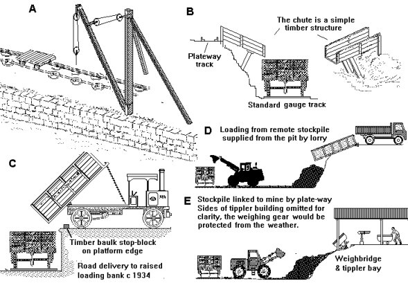
A feature of any railway loading point where there would be regular flows of traffic, at the mine or at a remote loading area, would be the wagon weigh-bridge (see Fig ___). Small loading points on a minor branch might do without, the wagons could be weighed in at some other location on the line, but the room required is small and I suggest you include a weigh-bridge where the siding(s) approach the running line.
One problem common to all mines is the disposal of waste material or gangue. In open cast mines and quarries this can be dumped in worked-out areas but in drift mines and shaft type mines it is hauled to the surface and piled up. A characteristic feature of mining areas is therefore the big piles of waste, usually called 'spoil heaps' or 'slag heaps'.
With a small mine the miners would not bother digging out any waste they did not absolutely have to (they were only paid for coal or whatever) so once the entrance to the mine had been created they tended to simply mine away the seam, even if this meant working in a space only a foot (30cm) or so high. Small mines therefore would have only a small initial waste pile and this would grow only when it became necessary to work round some obstacle such as a fault in the ground.
As mines were dug ever deeper however more waste material had to be removed and the resulting slag heaps were often very big indeed, much too big to include on a layout. To give some idea of the scale involved the Aberfan disaster of 1966 involved a landslide from such a tip which swept down and engulfed half a village. The slide involved only a tiny proportion of the heap and the remaining tip is still there, towering above the village.
The waste was initially tipped from the same kind of small wagons used to shift the coal. As the size of the pile increased however it became necessary to make special provision for shifting waste to the tipping site. In the North East a number of collieries were located close by the sea and one common practice was to lay a line to a near-by cliff and dump the waste over the edge. The waste contained small amounts of coal and up to the 1940's poor people would search through the pile to recover this for sale.
Inland the mine owner had to pay for the land on which to tip and pay to move the waste to the tipping point. From about 1920 some mines began using aerial rope-ways to transport the waste. These are a practical modelling proposition as they were only used when waste material was being cleared from the mine so they do not need to be operational all the time.
The rope from which the tipping buckets were suspended was supported on metal structures resembling power pylons and here we can make use of OO scale etched lattice signal masts for the main structure. The cross bars can be made from plastic and the rope is probably best represented using thin wire painted in a dirty brown mix.
Fig ___ Rope-way for a coal mine
As recovery techniques have improved over the years it has become economically viable to re-process mine waste to extract more of the desired minerals. If modelling the period from the 1970's a closed down coal mine is an option, there were usually large stock piles at the mine which took several years to clear. In addition there have been several industrial uses for the waste from slag heaps, from the mid nineteenth century to at least the 1940's brick works were set up to use the 'shale' type of rock (actually a rather solidified form of clay)in which some coal seams were found (see also Pottery and Brickmking).
Where metal ores were mined they were (typically) crushed as part of the process of separating the ore from the unwanted materials. By the 1930s an alternative method, involving crushing the rock to power and using an oil bath to separate the ore from the waste. This was more efficient but one advantage of the older crushing system is the production of a large proportion of gravel-sized tailings for which there was a ready market either as gravel or for road dressing or as concrete aggregate. Fluorspar, associated with lead mining, has proved a valuable by product. The fine grinding necessary for the flotation concentration method produces nothing but sands and slimes, which are not in demand as by-products and marketable gangues are rare.
There are understandably several museums and heritage centres associated with the mining industry, details have been included under the respective headings below. If considering a mine for your layout a visit to any of the listed centres is worth considering to obtain useful details, you may find that a drift mine such as that at Millom suits the space you have available and there is no reason it could not be adapted from iron ore to coal or even clay for a brick works.
____________________________________________
^
Go to top of page