General Engineering and Shipbuilding
Engineering Works
The idea of having a factory which took in orders for machines, and which made the parts it could not buy, dates back to Watt & Boulton in the 1790's. The production of machine tools, with which machines could be made, soon followed and by the 1890's most towns boasted at least one engineering works.
The range in size of the works makes this a difficult area to summarise, some works occupied more land than their associated town, other were little more than a shed in a side street. A larger works would almost certainly be built close by a railway line for delivery of materials and many featured their own railway siding or even an internal railway system.
Early engineering works built machines to order, often of their own design, and most would turn their hand to any project that offered the prospect of a profit. By the end of the nineteenth century there were many specialised engineering works, those in the country were producing farm machinery whilst others were building machines for local industries such as mills. Near the coasts large works were making parts to be sold to ship builders and there were many firms making stationary and mobile steam engines of various kinds. There were as many designs of factory as there were products produced although some elements were common to most. The various elements of a larger engineering works would often be housed in separate buildings.
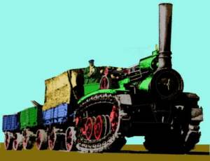
Quite a few works, particularly those in more rural locations, had a limited foundry or forging capability and the combination of foundry, forge and larger engineering works was a sensible arrangement making the works almost self sufficient (it would still buy-in nuts and bolts, hacksaw blades and the like from specialist suppliers). The company name is not always an accurate guide to their product range either, a notable example being the Vulcan Foundry of Newton le Willows, this firm was set up in 1832 as Charles Tayleur and Company (the name changed in 1847) to produce metal work for the Liverpool and Manchester railway (girders for bridges, railway line etc). By the later 1830s they were building steam locomotives for both the UK and export markets, in later years they built engines for the Midland Railway and the LMS and WD 2-8-0 engines. The built a fleet of electric locomotives for India in the 1920s and built numerous diesel locomotives as well as rolling stock (much of it for export). After the war there were a series of take-over's and the works closed in 2002. The works were rail-connected and there were some truly splendid machines produced there, the example below is a steam tractor on caterpillar tracks, built for the Klondike Gold Rush in the Yukon (Canada) in the 1890s and would make a rather different load for a drop centre wagon.
Fig___ Steam traction engine (1890s)
A typical large rural factory, producing say farm machinery, would include stores for both bought-in materials and its own produce, the foundry would be a moderately large building with the chimneys of one or two cupolas sticking out of the roof. Associated with this would be the pattern shop and possibly a store. The forge would require a chimney and was often an open-fronted building for ease of access and to allow the air drawn in to keep the workers reasonably cool. There would be a large 'machine shop' in which the parts of the machines were finished, this would house the lathes, drilling and milling machines and what have you. Possibly incorporated in the machine shop would be the erection shop where the machines to be sold were put together for testing (in many cases they would then be dismantled for ease of shipping). A boiler house or two would be used to generate steam for the machines and somewhere there would be the firms offices, usually in a separate building generally located some distance from the dirty parts of the works such as the foundry.
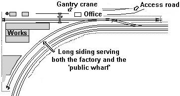
Fortunately in the present context much of the factory can be represented by low relief structures on the back scene, with the railway siding and associated loading bank to the front. As mentioned in Railway Company Goods Facilities - Prototype Goods Yards and wharfs these industrial sidings were sometimes combined with a 'public wharf', this was usually where the factory was in a rural area and was often a condition laid down by the railway company when the industrial siding was being arranged. Two examples of these combined factory and public wharf sidings I know of, both on the North Staffordshire Railway, were the Vulcan Foundry and the Foden commercial vehicle works.
Fig ___ Rural Engineering works with 'public wharf'
In towns the situation was rather different with many smaller firms offering limited facilities such as forges and foundries as well as specialist machined products such as nuts and bolts. There would be larger industries, for example a motor car works (discussed separately under Motor Cars, Commercial Vehicles, Construction and Farm Machinery), but these would be surrounded by many smaller engineering works, some consisting of a small shed no larger than a domestic garage. There were also quite a few 'cottage industries', notably those associated with iron and steel, such as chain makers.
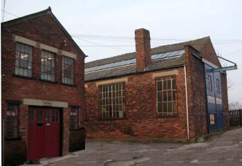
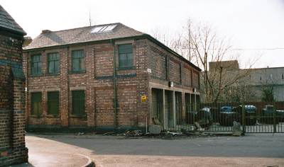
The example shown below is a small engineering works on a side street (the photograph was taken standing on the high street). The squat chimney suggests they had a forge in the larger building and the steel girder overhead conveyor suggests they dealt with some heavy equipment that was lifted on and off lorries. There again a firm making bolts from metal rod might employ such a crane to bring in the bundles of rod and once installed it would remain even if the firm using the building changed to one dealing with lighter engineering projects.
Fig___ Small engineering firm in a town
The demand for engineering works lead to standard buildings being produced, although used for widely differing purposes. The example below is now in the landscaped grounds of Manchester University but was once on a side street, and there is an identical building about a mile away, both were used for various enterprises during their lifetime.
Fig___ Standard design small engineering factory building
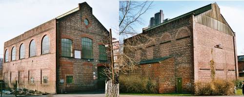
In the photo on the right you can see bricked-in arches along the upper sides above rectangular bricked-up window openings. On the other example of this building the arches were open as the firm there had a forge or foundry in the building and needed the ventilation. Open arched vents of this type were quite often seen in buildings associated with gas works and the like where ventilation was an issue.
This particular building was used by a firm building large electric motors prior to being taken over by the University and there was a separate stores and office building across the yard. Incoming traffic would include wire and small cable (small cable drums about three foot in diameter might be used for these), crates and cases of bearings and major sub assemblies, drums (possibly a tank wagon) of varnish, oil and de-greasing agents (methanol or alcohol).
Fig___ Stores and offices building
The corner of the building on the left of the above photo is the old back-street school building, this was a typical in-town built-up area with the factories intermingled with the houses. The school building is now home to some form of civic body.
Fig___ School opposite the factory

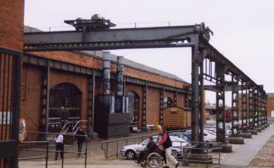
A larger works can be suggested by having a low relief building on the backscene fronted by a cobbled yard containing a gantry crane, the Manchester Museum of Science and Industry has such a building, once an engineering works now the 'power hall' of the museum, the crane and the two lines of inset tracks remain in place in the yard area.
Fig___ Large gantry crane in a factory yard
One firm you would be likely to find in and near most industrial towns and which might well have such a yard would be a boiler maker. These not only produced steam boilers but also a range of other goods involving curved plates welded or (more commonly) riveted together. They also produced curved, cut and shaped girders and the like with the necessary holes punched for the rivets or bolts used to hold the structure together. Prior to the development of large machine tools in the early 20th century problems were encountered in punching the holes for rivets so they would line up during assembly and a common tool was the 'drift' a tapered rod used to bring holes into alignment (this caused stresses in the metal and was responsible for many boiler explosions). The solution was to bore the rivet holes, although prior to the introduction of machine tools this meant a man with brace and bit working on chalk marks. For girders and the like the punched holes, not being under such great stress, remained common. Where pipes needed to be joined that would be under pressure a specialist worker (called an angle ironsmith) was employed to form a flared end or flange (this was not made a right angles but in a curve for greater strength). At larger works, by the early 20th century, a heavy hydraulic press was used to form these flanges. The introduction of mild steel in place of wrought iron made everything more difficult as steel is more liable to crack under such treatment. Riveting was done by teams of two men, one on one side with a block, the other on the other side with a hammer, by the early 20th century the hammer was usually hydraulic or pneumatic, but the noise of riveting remained a characteristic feature. By the 1920s boilermakers often concentrated on a limited range of goods, enabling them to invest in specialised machinery. One firm might specialise in making steam boilers whist another opted for bridge girders etc. Smaller firms, especially in more rural areas, continued turning out a wide range of goods as the demand for any single product was not sufficient to sustain them.
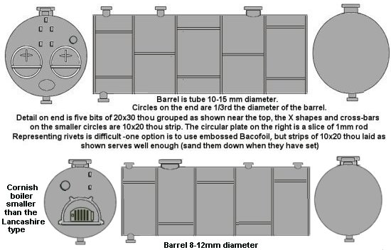
Fig___ Typical Lancashire and Cornish boilers
One job for such a firm would be the repair of older boilers, replacing the fire tubes and re-riveting the joints or replacing sections of shell plate. Traffic in would include regular shipments of col and coke as well as sections of plate, angle (girders) and bar on plate and flat wagons as well as materials in open wagons and (to a lesser extent) vans. Boilers are (in the main) big and would be shipped out on flat wagons, smaller items would likely be crated (see also Wagon Loads & Materials Handling - Wagon Loads - Introduction).
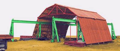
The boiler maker worked with plate, curving these to shape and riveting or welding them to make things, hence they might also make tanks of various kinds (for example the 'boilers' used in tar distillers). The structure below was taken from a photograph, the structure was actually in the way of the thing being photographed and so its purpose was not explained but I believe it was used for final assembly. However in the yard there were a number of large curved plates which would be the sort of thing seen in a boilermaker's yard. Note the lower sides are not vertical (although the roof trussing is supported on vertical posts), this is because the gantry supports angle outwards from the top rail down to the ground and the sides have to follow this line.
Fig___ Interesting structure for a boilermaker's yard
By the early 20th century the oil engine was in widespread production, these internal combustion engines used petrol and a spark or diesel and compression for ignition. A related type was the gas engine, which used gas as a fuel. Smaller engines of this type would be shipped out in cases and crates but larger 'portable' engines (mounted on wheels and towed about to provide power for farm and other machinery) would be shipped out on flat wagons, probably with a tarpaulin cover. An example of a towed oil engine is illustrated under Wagon Loads & Materials Handling - Wagon Loads - Road vehicles and Farm Equipment and an example of a large gas engine that would have been shipped in a crate (and hence visible) is illustrated under Lineside Industries - Builders and Wood Yards.
One application for multi-cylinder oil engines was in powering tractors, aircraft and private and commercial motor vehicles. These engines would normally be shipped out in wooden cases.
Also outgoing would be the waste being shipped to a scrap merchant, where holes for rivets were punched there would be a lot of rivet punchings, where machine tools are used there is the 'swarf' produced by the cutting of the metal and where a forge is used there is a lot of 'hammerscale' (these are all described in more detail in the section on General Engineering and Shipyards).
Shipyards and boatyards
The British shipbuilding industry was once one of the great assets to the country, when World War One broke out British yards were producing more ships than all the other countries in the world put together. The shipyards supported a large number of peripheral industries from steel making to engine building. During the hard times of the 1920s and 1930s there was little investment and when the Second World War broke out the yards were busy but productivity was low. The Americans adopted welded hulls and mass production methods and within a few years were producing ships that did not fall apart. After the war there was a massive demand for shipping and the British yards were busy although there was little investment in new technology.
Up to the 1960s British shipyards used a lot of steel, almost all of it from British steel works and over 80 percent made from British mined ore, the British merchant fleet was still by far the largest in the world at the time. Most ships were still small by modern standards, three thousand ton cargo ships were common on the deep sea shipping routes, there were a great many yards but most were small by modern standards.
HMY Britannia (the former Royal Yacht) was built at the John Brown shipyard on the Clyde in 1953, partly as a floating advert for British shipbuilders. Her hull was constructed using riveted plates, this was a technology well understood in the British yards and at the time rivets were still stronger than welded joints (British ships had to have the curved strip connecting the vertical sides of the hull to the horizontal deck riveted well into the 1960s). Riveted plates however cost more, there is more steel as the plates overlap and riveting requires a greater number of skilled man hours than welding. On Britannia, just to make the point, they rebated the rivets then ground them flush to give a smooth finish to the hull. The British yards could turn out a very nice liner, however the demand for these fell from the 1960s on as air travel became the norm for long hauls. Britannia was technically part of the Royal Navy and built to be convertible into a hospital ship but by the time of the Falklands war she was incompatible with other warships and a P&O educational cruise liner was used instead. Britannia was retired in December 1997 (her last job was carrying the Governor of Hong Kong back after the hand over to the Chinese), she is now a conference centre in Edinburgh.
By the 1960s other countries were turning out the large numbers of simple but very large bulk carriers and oil tankers using the American welded hull approach and the British yards could not compete on building this type of vessel. The entire ship building industry was nationalised in 1977 but again there was little investment in modernisation and no new very large yards were set up to build the modern ships. By this time foreign yards had adapted their new yards to build the new generation of sophisticated ships. In the mid 1980s the British shipbuilding industry was privatised but many yards, still using equipment that predated the First World War could not survive in the modern world. By the end of the twentieth century the small rump of shipbuilding in Britain could barely remain in business (the Australians decided to invest in their own yards to build their new warships and even the Royal Navy are now (2007) thinking that their new ships might need to be built by the French). Lost along with the ship yards were all the associated industries (and the value of their exports); steel making, engine building, instrumentation and control and the myriad small firms which supplied items for the fitting out of ships from portholes to self-extinguishing ashtrays.
A large shipyard is a big industry, requiring a decent sized bit of land and a big river. The centre of most yards is the slipway, an inclined slope on the bank of the river on which the ship is built before it is allowed to slide down into the water. Surrounding the slipways would be cranes and other structures associated with the assembly and some open ground where the parts are laid out as they arrive. Beyond this would be a number of very big sheds in which the parts are prepared. Associated with the yard would be the 'offices' in which the designers work preparing the drawings and the admin staff handle the financial side. This was often surprisingly small, you could get away with something the size of a large six bedroomed detached house.
Shipyards need cranes that can reach over the side of the ships they build, but they need them to be as close as possible to the slipway to save on space. As a result they often employed either 'hammerhead' cranes or as shown below tall lattice cranes supported by heavy cables. To give some sense of scale the dark boxes on the crane masts are the operators cabs and if you look at the lower centre of the picture you will see a chap in a blue boilersuit (you may need to look closely, he is small).
Fig___ Ship builders yard cranes
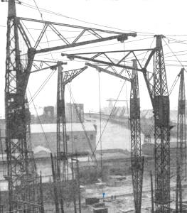
This was a big yard, photographed in the 1930s, hence the cranes were very tall indeed. Smaller versions of this type of crane were used at smaller yards however, and they can be modelled in N using a pair of Slaters OO scale lattice signal masts, glued base-to-base. The cab on the smaller version would be mounted on the side or front of the mast, with the braced L shaped jib mounted above it. The jib was a box section (for which plastruct square tube would serve) with heavy wrought iton or steel trussing on the top (which you can make from Slaters Microstrip).
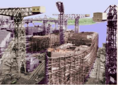
Shipyards were in practice densely packed areas, the example shown below is a typical large British yard of the type familiar up to the 1980s, this example is the John Brown yard (where they built the Royal Yacht Britannia) on Clydebank. There are two slipways, each with a ship being built, I have traced the lines of the singe rail track running up either side of the ship in the foreground to give a sense of scale (the opposite bank, shown covered in foliage, would typically be an industrial scene). This yard uses the 'hammerhead' type of crane which is actually the more difficult type to model.
Fig___ John Brown & Co ship yard on the Clyde
Because of the space required there have only been a few shipyards represented on model railway layouts, although I remember seeing a rather splendid example described in the N Gauge Journal in the 1970s which used the well known 'Shell Welder' kit, somewhat cut about, on the slipway itself. The yard itself was (from memory) about two feet (60cm) long by about eighteen inches (45cm) wide, which is about as small as you can go and still represent a large yard. One problem is the vertical space occupied, making it difficult to reach into the yard are to retrieve wayward rolling stock.
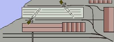
One option is to place the slipway against the rear of the layout, with the far side of the river painted on the backscene. In front of the slip would be some of the large sheds associated with the yard, and these can be rail-served. In the example shown only the two sidings at the front (running under the large gantry crane) are 'live', the remaining trackwork is dummy (a couple of vans and perhaps a three wagon rake of one to five plank wagons serves to suggest they are part of the system). The layout as shown would be a minimum of about eighteen inches (45cm) long. The track feeding into it would be an industrial siding from a yard rather than a siding of a normal running line.
Fig___ Shipyard at rear of layout
You can reduce the depth still further by having a slip that launches ships sideways, not uncommon at smaller yards (I think you can go up to about 3000 tons with a side launch, but I could be wrong either way in that). The side-launch slip allows a ship to be modelled in half relief and does not require a quay wall for the far side of the slipway.
These open slipways becamme the most common type in the mid 19th century, associated with larger ships built using iron and steel. Prior to this the ship was often built inside a large building at the top of the slipway, protected from the weather and close by the work benches used to make the parts. The masts, derricks etc would then be added when the ship was in the water (this fitting out work requires a lot of headroom and a big crane). The covered slipway came back into favour at larger yards in the 1970s, although mainly associated with warship building yards in the UK. The advantage of having a covered assembly shed is the simplicity of modelling, this is also the main drawback as the result is less interesting both the make and to look at. There are several examples of the covered yard, searching the internet for Appledore Shipyard or Vickers Barrow Shipyard should produce several illustrations.
Traffic into such a yard would include a lot of steel plate, so plate and trestle wagons would be common, and a lot of timber used for various purposes including cladding metal decks on passenger ships (and on the accommodation decks of cargo ships well into the 1960s). Shipyards use a lot of shot-blasting grit and of course a great deal of paint. Pipework would be delivered as lengths and bends, a ship uses a lit of pipes. A larger yard would be likely to cast its own propellers, sometimes its own anchors, but either or both might be bought in for a given job. This anchor chain is supplied in lengths called a 'shackle', 15 fathoms (90ft/27 metres) long, these are joined using a special two-part link in the chain (the 'shackle' itself). Anchor chain is heavy stuff on a ship of any size, so finding a supply for N Gauge is not difficult. Mooring ropes would be supplied as large rolls rather like a ball of very thick string, about eight feet across and five feet tall with a hole down the middle about three feet across. Glass wagons might be required to bring in the panes for the bridge front windows although most glass for the portholes (square windows) and scuttles (round windows) would arrive in vans, as would the associated fittings. By its very nature a ship requires almost anything imaginable to be put on board, including machine tools for the engine room, large and small steam engines, electric motors and boilers (even on a motor ship there are boilers, including one in the funnel, heated by the exhaust and used to drive a turbo-alternator for electric power when under way and on pre-1970s tankers to drive the cargo pumps).
At the smaller end of the scale is the 'boat yard', building fishing boats, smaller coastal craft and pleasure boats. One point to note is that there have been fashions in small boat design, up to the 1950s most river craft and pleasure boats had a straight stem (the pointed bit at the front was vertical). It is worth searching for photographs to get a sense of the designs seen in any particular era.
The smaller boat yard would not usually be rail connected but they can be used to fill a space on a layout, adding a scene of some 'industrial' interest in an otherwise rural scene. A good example of a small riverside yard can be seen on the Madder Valley layout, preserved at the Pendon Museum. The boats are hauled out of the water on a wheeled carriage (being repaired rather than built) which rests on a concrete ramp with inset rails for the carriage. The example sketched below has a wooden carriage, similar to the example on the Madder Valley yard, to handle larger fishing boats a larger carriage would be required. Carriages of this type are fine for boats and coastal craft up to about a maximum of a hundred tons in weight (ship models based on the Thomas the Tank 'Bulstrode' model would be right at the upper limit).
Wooden ships and boats were limited in size by the characteristics of the wood itself, when the Caledonian Canal was built all craft were wooden and the canal could take the largest vessels likely to be traveling round the top of Scotland. Once iron and then steel became the norm this canal, and many other facilities, soon found that ships were getting too big to handle. Hence if you want a small boat yard have them building wooden hulled craft, pleasure craft would only require a small yard, however they would be unlikely to have a railway connection laid in.
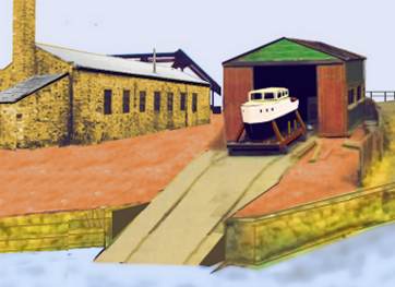
To make the curved parts of the vessel it was standard practice to place a straight piece of timber in a 'steam chest', typically a light metal box through which steam was passed. The steamed wood can then be bent into shape, where possible this was done in the chest itself, forcing the wood to shape before admitting the steam. In the example below the building used for building the boats is a bit small so you need a separate building to house this facility, any single story industrial building would serve, the example shown below happens to be made of stone, note the attached boiler room and tall chimney.
Fig___ Small riverside boat yard
Not shown in the example sketched above is the clutter associated with any yard of this type; wooden barrels and steel drums, planks and baulks of wood, probably a couple of small carpenters trestles, pots of paint, rope (coiled and odd lengths) chain etc. Yards dealing with fishing boats, small coastal vessels and the like would probably have a crane or two.
Ships are built using a series of vertical frames, formed to the required shape of the hull, which are then clad in planks of timber or plates of metal, the vertical frames are only a couple of feet apart, so modelling a half-built ship is a protracted exercise.
The introduction of metal frames, and later metal hull plating, brought many changes to the ship yards, not least in the amount of metalwork left lying in the yard, in yards I have visited there were often complete sub-assemblies, a lot of plating (often stacked a couple of feet high), pipework and odd sections of girder. This clutter is piled in defined areas, leaving space for easy access between these areas.
Dockyards and drydocks
Once the ship has been launched it is often taken to a 'dry dock', a chamber with lock gates that can be pumped dry so the ship's hull can have further work done on it. One job done here is the removal of the metal brackets on the bottom of the hull used when building the ship and to allow it to run down the slipway without falling over on its side.
The dry dock is often a separate entity from the ship building yard, these are known as dockyards, and are usually associated with on going maintenance. T Associated with a dockyard there would be one or more dry docks, older types have stepped sides leading down into the dock itself, larger and more modern docks have vertical sides with stairways set into the side walls. ypically ships are dry docked every three years, at which time the ship is checked over and any jobs that could not be done at sea are dealt with.
Smaller vessels tend to have rather pointed bottoms and have to be propped up in the dry dock,usually with timber posts set against the dock sides, this would apply to tugs and some coastal craft (although many of the latter were designed to sit on the beach when the tide went out and so had flat bottoms). Larger ships have fairly flat bottoms, these are supported in the dock by blocks of concrete, laid out to allow access to important parts of the hull such as seawater inlets to allow work to be done on these.
One common job in drydock is shot-blasting the hull and re-painting it, so you would expect wagon loads of blasting grit, supplied in bags. Spray painting has been the norm since the 1960s.
Also in the dockyard are the quays where ships are tied up for final fitting out, known logically enough as 'fitting out berths'. A lot of equipment on a ship requires the hull to be in the water for testing purposes, for example sea going ships use seawater as part of the cooling system for large marine diesel engines. The fitting out quays, and the dry docks themselves, would have substantial cranes (the Dapol 'dock side crane' is typical of the type used, these are heavier than the cranes used for cargo handling at the docks but (generally) lighter than the cranes in the shipyards).
^
Go to top of page
International Good Guys ~ Making the world a
better place since 1971 ~ Site maintained by

All material Copyright © Mike
Smith 2003 unless otherwise credited