Electricity Generating Stations
Note -
At the time of writing (late 1990's) coal is still the source of most of the UK's electricity, details of the history of the British electricity supply will be found in Appendix One under General information - Fuels (Coal, Gas, Oil and Electricity).
Consumption of electricity in the UK has doubled about every ten years since the beginning of the century, in the early years there was much debate regarding the relative advantages of Direct Current and Alternating Current. The Americans, lead by Edison, favoured the former, suggesting that a small power station should be built for each neighbourhood. In Britain Ferranti championed the use of a large and efficient central power station supplying high voltage AC which could be transformed down to a suitable voltage for local distribution. The more fuel efficient AC system was eventually adopted as the British standard supply but DC supplies remained in use in some homes into the 1940's.
Power stations were built by both private companies and also town councils (or Corporations), in 1883 the first publicly owned electricity generating station was built by city of Worcester on the river Teme at Powick. By 1919 there were over 400 power stations supplying electricity, using AC and DC with a range of voltages and AC supplies further complicated by variations in frequency and numbers of phase supplied. The result was that electricity was difficult to use and Britain had about the lowest consumption of electricity of any industrialised country. On the plus side this means that, right up to the outbreak of World War Two there were small power stations that can be conveniently modelled on a layout.
The Royal Commission of 1919 began the reorganisation of power supplies, the plan was to reduce the number of power stations to just 122, all coal fired (other than a couple of hydro-electric stations). In 1926 the Central Electricity Board was established to buy all the power supplied (it did not own any generating stations and only supplied power to larger installations and (more commonly) to third party distributors. The interconnection into a national system (the National Grid) with a transmission line voltage of 132kV (132 thousand volts, dropped to 66,000 volts for underground cables in cities) was started in 1928 and virtually completed by 1933. A standard three phase, 50Hz supply was settled upon. By the outbreak of World War Two however there were still a lot of smaller (and less efficient) power stations in use, which was perhaps fortunate as it made the job of the enemy bombers more difficult and allows us to add one to a model layout. In 1949 the electricity generating stations were nationalised, in 1956 the power stations became part of the Central Electricity Generating Board or CEGB. The rail fed power stations were fond of PO wagons to deliver their coal, often large and often end-tipping designs, the CEGB also purchased a number of PO wagons for its own stations which ran in CEGB livery.
Early generating stations used steam reciprocating engines or occasionally oil engines (diesels in modern parlance) to drive the dynamo's and alternators via flywheels and belts or gearing. The steam driven stations would have a boiler house with a tall chimney and a separate (possibly adjoining) building to house the engines and electrical generating plant. They might have their own private siding but might equally well have their coal and other supplies carted in from the local goods yard.
Power stations and other large industrial establishments use large quantities of coal and the best way to deliver the coal by rail is from hopper wagons. Both the LNER and LMS built hoppers of various designs for feeding power stations but in many locations standard open end-door wagons were commonly used, emptied using an end or side tipper arrangement (see also Wagon Loads & Materials Handling - Materials Handling - Bulk Minerals).
Coal was the usual fuel for power stations and there would be a coal stockpile, probably 'round the back' close by the boiler house. In medium to large plants the coal handling would be mechanised, with incoming coal fed directly into large hoppers to supply the boilers. In an inefficient plant around the time of the First World War it required anything up to 5lbs (2.25Kg) of coal to produce 1kWH of electricity, by the 1940s the more efficient stations used just over 1lb (0.5Kg) of coal per kilowatt hour. Some smaller power stations used oil fired boilers, allowing you to use tank wagons and thereby avoiding the problem of arranging for full and empty wagons.
Other cargo that might be delivered by rail might include oil for transformers (see Lineside Industries - Lubricating Oils and Associated Works) and drums of cable (see Wagon Loads & Materials Handling - Wagon Loads - Introduction). Occasional van loads of equipment might also be seen, but coal would dominate everything.
Electricity generating companies were set up wherever a demand existed, some occupied existing industrial buildings ( at Salisbury the power station was in a converted water powered flour mill) and often had no direct rail connection (although a flour mill might well have a siding or two).
A smaller purpose built electricity generating station can be represented by a brick building, possibly with an ornate frontage containing the boilers and turbines or dynamo's. If visible through the windows the steam engines or oil engines would be painted black whilst the generators were often painted light green. The name of the company operating the station was often displayed, generally in contrasting brickwork, on the side or end of the building. The Peco engine shed would serve well as the building holding the generating plant, turbines, dynamos or alternators.
My local town was supplied by a company operating a number of such buildings, some contained the reciprocating engine and generating sets, others the boilers (feeding several generators) and a couple of the early buildings contained both. The power in my local town was (initially) supplied using metal bars, sitting on glass insulators, running in small tunnels under the streets. Various combinations of connection to these bars produced a range of voltages to suit the customer. Later the bars were replaced by insulated cables. The advantage of this system, if your layout is on the outskirts of a town, is you need not model the power lines.
If you wish to add the overhead supply lines the early stations tended to use quite a lot of timber, all of which seems to have been black with preservative, with the cables suspended or supported on glass insulators. Modelling these timber pylons is discussed below. Larger stations favoured metal lattice structures to support the cables, for which a good rummage in the bits box is required, and tall metal pylons (Scale Link offer an etched metal pylon kit) for the cross-country feeds.
Outside the buildings, where high voltages were being produced, would be the transformers and switch gear.
Piko offer a small enclosure containing some transformers and high tension switch gear (60016). These latter are intended for the line side on an electrified railway but a couple of these kits located close by the generating station buildings would serve well to identify a power station.
As noted above take up of electricity was slow in Britain, in Hemel Hempstead for example gas was available from 1869 but electricity was only available after 1926.
Quite a few power larger stations received their coal by sea or via a local canal, on the Aire and Calder Navigation they built special steel barges, initially for coal being shipped by sea and later to supply the power station. Called Tom Puddings these were square in shape and towed in long rakes along the river or canal to the station where they were lifted in a large frame and tipped. These purpose built barges remained in use at the power station into the mid 1980's. The barges were however often loaded from railway wagons, so one option is a barge loading point. Battersea power station was located on the banks of the Thames and unloaded its coal from barges using cranes and grabs. The coal was dropped into hoppers which filled small wagons on an elevated railway which ran into the boiler rooms at one end of the building. From about the 1930's vacuum unloading was used at some stations as the coal delivered was small, however this was usually confined to unloading from barges.
Coal, gas and nuclear power are all used to generate steam for turbines, coal has been by far the most important fuel but government policy in the 1980s saw a shift to the use of gas as supplies from the North Sea could be used. Nuclear power stations were inextricably bound up with the need to develop nuclear weapons and only appeared after the Second World War. Britain was the first country in the world to develop peaceful nuclear plants, Calder Hall in Cumbria came on line in 1956 (nearby Workington was the first place in the world to have nuclear generated electricity supplies). Calder hall, part of the Sellafield/Windscale complex continued producing weapons grade materials until the early 1990s. Unfortunately the British nuclear plants were built in a hurry at a time of severe economic hardship and suffered as a result, there were a number of accidents, some of them serious and producing contamination over wide areas, but all were covered up to avoid embarrassment in Whitehall.
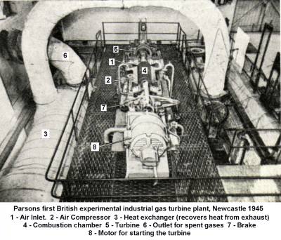
Another post war power station development was the gas turbine (a jet engine) used to provide power for a generating set. These cost a lot to run but can fire up in seconds. Major power stations usually have a gas turbine available that can be fired up to deal with sudden peaks in demand (such as at the end of the TV news when several million people tend to put their 3KW electric kettles on). Larger stations used to have someone monitoring a bank of TV's, if there was an interruption in the normal broadcasting they could press an emergency start button to bring the gas turbine on-line to cope with the sudden demand from all the kettles. In the 1980s the standard kit was a Rolls Royce Olympus turbine, originally developed for aircraft but also used on some fast warships (notably the Amazon class frigates). The photo below shows the first small experimental industrial unit built in 1945 by Parsons in Newcastle.
Fig___ Parsons 1945 Industrial Gas Turbine
Virtually all of the (generally larger) stations built after the turn of the century used coal fired boilers to supply steam turbines and high speed generating sets (invented in the 1880's). Parsons, the firm founded by the inventor of the steam turbine, is the largest British supplier of this equipment. To differentiate them from hydro-electric stations coal and gas fired power stations are known as 'thermal' power stations. Although technically thermal the nuclear power stations are always called nuclear.
The coal would be supplied from the on-site stockpile via a conveyor feeding into the upper part of the building. A station built in the later 1930s might have a stock pile of up to 35,000 tons of coal to allow for interruptions in supply. As such a station would typically burn up to two thousand tons a day that is only enough for two and a half week operation.
Early boilers used normal coal, fed into large hoppers and thence into the firebox of the boiler. It was common to use a conveyor belt of steel rods (called a 'chain grate stoker') to carry the coal through the firebox, depositing the ash at the far end. Pulverised coal, ground down as fine as flour, can be blown into a boiler and burns rather like gas, this is an efficient way of using coal but the plant costs more and produces more fine 'fly ash' (discussed below). On the plus side it offers greater control of the burning, simplifying the operation of the plant, and can make use of poor quality coal. Pulverised coal was in use by the early 1930s, being shipped pre-powdered from the colliery in sheeted open wagons. The collieries liked this as they could recover the coal dust and grind up the small pieces of coal that did not sell well and pass this all to the power stations. Power stations using pulverised coal would also have pulverising gear so they could use ordinary coal supplies (not least because stockpiling powdered coal in the open is impractical as it tends to blow away).
Fig___ Boiler control panel from the 1930s
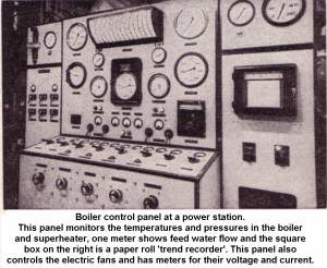
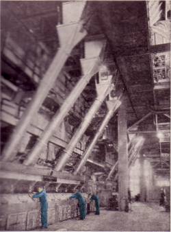
The boiler rooms in a steam turbine power station were larger than the turbine halls, typically twice as high and with about three times the floor area. These had few windows and the interior was quite dark, so a dark grey inner structure is all that is required. The boilers are always of the water tube type. These are encased in large rectangular sheet metal housings with the feed tubes for the coal supply running down at a steep angle to the firebox. In the photo below, taken from a 1940s school book, I have tinted the figures as they give a sense of scale. Known as the 'firing floor' this is now a clean area due to the mechanical feed (men with shovels just couldn't keep up with the demands of these large boilers) The control panel shown above would be located in this area.
Fig___ Coal feed tubes in the boiler house
The waste gases from the furnaces are passed to an 'economiser' where they are used to pre-heat the feed water for the boilers, then they are cleaned to remove ash (discussed below) and since the 1980s they have increasingly been washed to remove traces of sulphur before being passed to the chimneys. The boilers do not rely on the draught produced by the chimney, they also have large fans to blow air into the fire box, giving the additional advantage of greater control over the burning of the fuel. Incidentally when Battersea was first built in 1931 it had only two chimneys, the second pair were added in the 1950's.
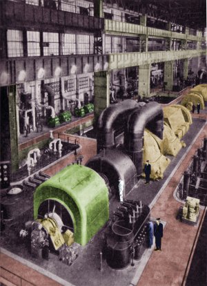
In larger stations the turbine hall has many large windows (those from the Peco engine shed kit serve well for this) and this means you should include some degree of detail inside the building. The illustration is taken from an old engineering book, I have attempted to colour it (from memory) and have added a few high contrast figures to give some sense of scale. In N the detail need only be suggested, cut down 'party poppers', cotton reels and bits from the spares box can all be used. Not the walkways (tinted brown) are raised by five or six feet and there is a lot of pipework etc below them.
Fig___ Turbine hall
Turbines in the later 1930s settled at a typical size of about 60 MW output, by the early post war era this was increasing to 100 MW. A speed of 1500 RPM was standard pre-war but post war stations favoured 300RPM sets as these are more efficient. Pre war generators produced (typically) 11KV output, post war this started to increase with many stations switching to 33KV alternators. Post war developments included the use of hydrogen gas to cool the actual alternators, hydrogen absorbs more heat than ordinary air and offers less windage or drag to the alternator rotor.
The steam exhausted from the turbines is passed into condensers where it is recovered to be re-used in the boilers. The condensers produce a drop in pressure (actually a partial vacuum) as the steam turns back to water, increasing the pressure difference across the turbine and greatly improving its efficiency. The cooling system in the condenser uses cold water to condense the steam, if the station is near a river the river water can be used, where no river is available and no suitable water supply is available the cooling water must itself be allowed to cool and is then re-cycled. If a river is close by the river its water can be used as coolant, this must be cooled before being returned to the river otherwise it would kill everything in the river. The hot water from the condensers is usually cooled in cooling towers, essentially a large hollow structure in which the water is sprayed out over a rack of horizontal slats, some being lost as steam, the rest condensing and falling into a large pond in the base of the tower. Typically about a third of the water taken in is lost as steam, mainly from the cooling towers, but the remaining two thirds is returned to the river.
A large power station might require upwards of 100,000 gallons of water a day over and above any that it can recycle, hence to popularity of river side locations. Almost all British power stations are located close by a river. The Iron Bridge power station on the river Severn uses a hundred million litres of water a day, which is about half the flow of the river. Where the river is deep enough it is common to use coastal or canal craft to deliver the coal, at more inland stations the railways are used. One point to note is that the ground on which the station is built has to be fairly solid, a turbine and generator without the boilers can weigh in at 1500 tons.
For a turbine equipped station at least two cooling towers close by is a requirement, oil engined or direct drive steam engine generators do not need these. Cooling towers at turbine power stations tend to be large wasp-waisted concrete structures (introduced in the 1920's) which are difficult to model but smaller stations would have the more easily modelled wooden type.
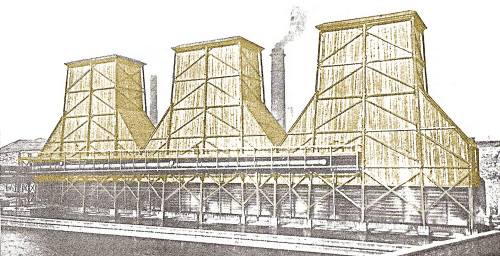
I was fortunate to be in contact with Mr. David Bowie, who is something of an expert on these matters and he was able to provide a number of illustrations. The example shown below was built for Bradford Corporation. Mr Bowie advised:
These were the Valley Road Bradford Davenport Towers. A set of three circa 75,000 gallon per hour towers arranged over a common cooling pond at the former Bradford Corporation Valley Road Power Station, (this was adjacent to the main
railway line to Bradford Foster Square station). These must be the largest wooden construction cooling towers that I have seen; estimated to be in the order of 140' high, with a base size of some 90' x 41'. Since the height is very much extended in comparison to the area of the base,
these proportions are fundamentally different from all of the other Davenport "Bradford" towers. This must have been principally concerned with mist dispersion.
Fig ___ Wooden cooling towers at Bradford
Wooden and other types of cooling tower are more fully described in Lineside Industries - Prototype industrial ancillary structures.
The wasp-waisted concrete type of tower is supported on legs at its base to allow air into the tower, the wooden type have a slatted base for the same purpose. There are usually two towers, allowing one to be shut for maintenance whilst the other handles the full load.
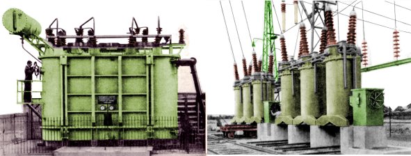
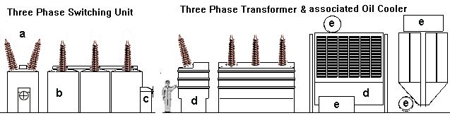
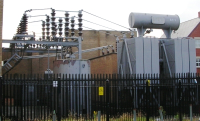
In the 1920s the shift to a standard high voltage supply brought a requirement for special switching equipment and large transformers, both of which were often mounted outside in a fenced off enclosure. The Piko small enclosure with transformers and high tension switch gear (60016)serves well enough for a small power station (viable up to the later 1930s in more rural areas). Bigger stations would have bigger transformers and switch gear, the switches would typically consist of three oil filled cylindrical tanks, one for each phase, each with two insulators on the top to carry the input and output lines. At one end would be a box containing the gear to operate the mechanical switches inside the oil-filled tanks. Transformers were oil cooled and a typical design is shown below. The cylinder on top is the oil header tank, some transformers also had a separate tank on the side, functioning much like a motor car radiator, sometimes with an electric fan to aid in cooling the oil.
The illustrations below show (left) a very large transformer and (right) two banks of three-phase switches (the lines leading off to the upper right feed the first pylon taking the power to the grid).
Fig___ 3 phase high tension transformer and switches
The link below relating to larger power stations includes cut-aways of some of the gear used at power stations.
Insulators are either white or dark reddish brown, with the brown colour being most common ('brick' colour with a little added black will do for this). The insulators used can be represented using small wood screws although you will need to rummage about to fid some long thin types, the diameter at the base end should be no more than 2mm for N Gauge. The suggested method of construction is shown below, the switches can be represented using dowel (b) sanded to a slight dome at the top with short woodscrews (a) set on the top (cut off the head and glue to the dowel). The manual control gear is a block of wood (c), the end dowel being cut away (easier than shaping the block), a hand wheel can be added using the smallest metal press-stud you can find. The main body of the transformer and its associated oil cooler (d) are wood cut to shape, the cylindrical tanks (e) are small diameter dowel (the wooden sticks sold for bar-b-q kebabs would be about the right diameter in N) or lengths of straw packed with Milliput.
Fig___ Modelling 3 phase high tension transformer and switches
The high voltage cables from these units would be suspended with long white or brown insulators from lattice towers and gantries. These insulators can be represented using short lengths cut from 1mm diameter bolts whilst the gantries can be represented using parts from the Ratio LNER lattice mast OO scale signal kits, Plastruct warren truss sections and any other odds and ends in your bits box.
Etched metal kits for high tension pylons are available from Scalelink, although expensive a couple of these at least would be required to complete the scene for any of the larger stations built after the 1930's and feeding into the National Grid. Older installations used timber pylons, the examples below are sketched from photographs taken before the First World War. The double posted type are the main distribution pylons, note the example on the right is used where a road is to be crossed, the insulators were (I believe) white. The single mast with three red-brown insulators carries a single three-phase supply line pylon of the type used for rural (usually farm) supplies. The three phase farm lines on timber posts as shown were still seen in the early 21st century.
Fig___ Timber pylons (1900-1940s)
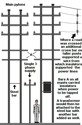
If modelling these you would be best using a template as they were all built to a standard size and any visible variation would look out of place. Wooden 'cocktail sticks' would serve for the masts in N (although slightly over scale they are at least all the same), for OO the longer type sold for use on bar-b-que's would serve.
One of the cheaper ranges of accessories (although I cannot remember which one) offers a set of single pole 'telephone poles' that are actually electricity supply poles, complete with a couple of double pole masts carrying step-down transformers. These would serve for rural British power lines in the pre-war ear and if anyone happens to know the manufacturer I would appreciate an e-mail. Telephone poles will have lots of insulators on them, power lines comparatively few.
Fig___ Modern suburban step-down transformer (2007)
The facilities for unloading coal wagons at a larger power station would probably best be represented using a covered tippler or bottom discharge bay built on a siding run alongside the main structure. The coal is usually moved from the unloading bays on conveyor belts which deposit the coal on the station stockpiles. From here the coal is lifted by crane grabs in to hoppers feeding a further set of conveyors leading into the upper part of the building. These conveyors are usually enclosed and can be represented by square section wood strips roughly 6 mm wide by 8 mm high. If you have the patience the Ratio Corrugated Roof can be cut up to form the top of these conveyor lines, or you can use corrugated metal panels made up from Bacofoil (see Lineside Industries - Available Models for Lineside Industries). If you are really enthusiastic you can model a section where the side panel has been removed, revealing a short length of conveyor inside. The side panels are typically six foot long. Where the conveyor was raised above the ground it was supported by a light frame which was held up by steel towers at about 20 foot intervals, Plastruct trusses would serve well for the former, the latter can be knocked up using plastic strip.
As noted above the trend was for larger stations and by the later 1930's there were very few small generating plants still operating. The link below opens a page containing a cut-away of a large river-side power station, typical of those built in the 1920s and 30s, this example uses colliers to bring the coal up the river but the buildings and contents would be the same for a rail-fed example.
Click her for cut-aways showing a large power station and also the switch gear used.
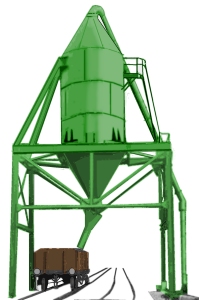
The end result of burning coal is of course ash and although this contains useful quantities of alumina, iron oxides, silica and other materials it is mainly just dumped. At some power stations the fly ash was collected in a tall tower resembling a 'cyclone' dust extractor located close by or above the sidings delivering the coal. The ash was dumped from this into open wagons and sheeted over before being shipped out. The example in the sketch below is based on a tracing of a tower at Clifton power station (near Manchester) in about 1915, the two tracks were used to deliver coal, the ash hopper was apparently added later. At the time the photo was taken the station was using twin pole timber post power lines as shown above.
Fig___ Power Station ash hopper
Power station and factory boiler ash consists of three grades; fly ash, bottom ash and boiler ash, but it is usually just called fly ash. With the increasing use of pulverised coal since the second world war the ash is generally known as Pulverised Fuel Ash, PFA for short. The most troublesome is the fine powdery fly ash, so called because it tends to fly up the chimney to the annoyance of local folk. An American called Fred Cottrell (1877-1948) invented the 'electrostatic precipitator' to deal with this stuff. This device consists of a wire suspended in the chimney with a powerful electrical charge on it. This induces charges in the fine particles which then stick to the sides of the flue in the same way that small pieces of paper will stick to a vigorously rubbed nylon comb. The ash is then periodically removed and this device has greatly contributed to the cleaning of the air in industrial areas.
A large power station might consume a couple of thousand tons of coal a day, producing a couple of hundred tons of ash. Where the fuel has been pulverised there is a lot of fine 'fly ash' which is dealt with by the electrostatic precipitators, larger ash is recovered using cyclone type extractor as shown above (but in larger stations these would be inside the furnace building. The resulting ash was often mixed with water and flowed into pits where the water is drained out and re-used. The ash, once dry, is then lifted out and put in either railway wagons or road lorries for transport. Some was used for various industrial purposes but a lot ends up in basic land fill sites.
Getting rid of the collected ash has long been a problem for the power stations, originally it was hauled away in sheeted open wagons, more recently (since the mid 1960's) the Graham Farish type Presflo wagons have been used for this traffic. The hoppers are washed as they leave the loading area and so are not stained or dirty. Most of the ash is used as land fill, principally to fill in large clay pits in the South of the country, where it is mixed with concrete and similar binding agents to keep it in place. About a third is used in producing building materials and as an 'extender' for concrete (producing a lighter material than solid concrete).
A large generating station would take up a great deal of room, with the railway connection running along the 'rear' and often an ornate art deco frontage to the main buildings. Inwards traffic would include regular large shipments of coal and perhaps van loads of insulators, cable drums and the occasional transformer. Outgoing would be wagon loads of ash. Such a facility would have quite a lot of land round about and would often feature its own internal railway system.
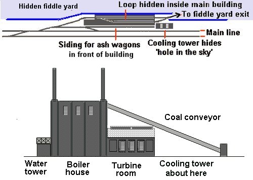
There are two options for modelling a large power station, firstly if you enjoy shunting the rear of the station buildings can be modelled in low relief on the back-scene with the area in front of this devoted to the rail connection. Alternatively you can run the siding feeding the station through the backscene and onward on a hidden track to the fiddle yard. By having two sidings forming a loop you can use these as storage lines to hold a loaded and empty train (each facing in the appropriate direction), allowing regular trains to run. The well known (American) Model Railroader magazine exhibition 'Clinchfield Railroad' layout has a 'mountain' at one end, inside which are two spiral tracks connecting a 'coal mine' near the top on one side with a 'power station' near the bottom on the other. Both industries are suggestively rather than accurately modelled (I seem to remember a German 'brewery' supplied the bulk of the parts for the power station), but this does allow regular loaded and empty trains running in the correct direction. The example below employs the same principal, additional detail might include the suggestion of a coal stockpile to the right of the cooling tower. In the sketch below the turbine room is a Peco engine shed, three of the windows from this kit are used, with rather a lot of brick embossed card, for the boiler house. The water tower hides the point where the sidings enter the building, the 'hole in the sky' is hidden by the cooling tower.
Fig___ Large power station with hidden return line
Combined Heat and Power Stations
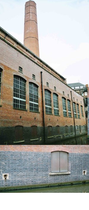
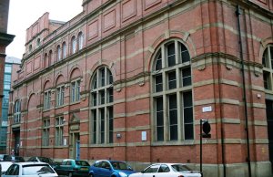
Central-heating systems, in which one centrally located heating unit is used to warm several rooms or an entire house, were developed in the 1800s. A type of centralised heating, using hot water, was used to a limited extent in Great Britain from about 1816, but the first successful central system, introduced in 1835, used warm air. This system subsequently came into extensive use in the U.S. Steam heating was developed about 1850, steam was centrally produced and piped to the customers, hence it was confined to densely populated towns (mostly in America). The steam was produced in the 'local' power station (the preferred option in the early days in the US) and today 'combined heat and power stations' are again being considered for use in British cities (see below). There have been British examples of CHP stations, one was built in central Manchester next to a canal and the coal was supplied by barge.
The canal side of the building was very plain, the small doorways just above the canal (detail view shown inset below) were used to get the coal into the boiler room, the rings on the walls being used to secure the barges.
Fig ___ Canal side of Manchester CHP station
The street side was altogether more imposing, being in the business district the building was designed to compliment the surrounding architecture.
Fig ___ Street side of Manchester CHP station
Where a lot of heat is produced as part of an industrial process it has been fairly common to sell that to neighbours (either other industries or as a domestic and commercial heat source). ICI built a large CHP plant in Runcorn in the 1990s that provided power to a number of local users (including domestic supplies, apparently at below market rate prices). The energy company PowerGen funded, built and owned the CHP plant which provides steam and demineralised water for ICI Chlor-Chemicals (the UK's largest chlorine manufacturer, now part of INEOS) and other industrial chemicals businesses based at the Runcorn site. The electricity generating station shown below is at Immingham and is operated by ConocoPhillips, who call it Immingham Combined Heat and Power or ICHP. The plant came on line in 2004 generating 730 megawatts of electricity and is one of the greenest power stations in the world (making a major contribution to reducing greenhouse emissions in the UK). The steam from the power plant is also used by the nearby Humber and Lindsey refineries. Fuelled by natural gas it is able to immediately switch to liquids from the adjoining refinery as back-up in the event of gas supply problems (reliable supply of steam is essential for the refineries).
It has four boilers (and can run on only two), the four chimneys are combined in the large tower visible on the left of the picture (this also seems to contain other equipment, probably an 'economiser' to recover as much heat as possible from the exhaust).
Fig ___ ConocoPhillips CHP station
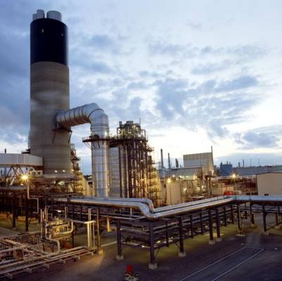
Image copyright and courtesy of ConocoPhillips
^
Go to top of page