
Multiple compartment beer tank wagon from the Peco kit I do not know how many of these were built (the wagon carries the number 22 but that may not be relevant), owned by Ind Coope, not sure when it was built but it was running in the immediate post war era. Quite a rare beast, handy as it can run in parcels trains, breaking up a long rake of vans (up to 1959 it could have run attached to a passenger train as well). The model is a Peco tank with the top detail removed (razor-saw from each side, angled upwards, the filler dome can be re-used on another model). If you find you have left grooves in the top of the tank with the saw fill these with microstrip then sand the tank sides to reduce the depth of the moulded detail. The ladders are not used so fill in the mounting space with a scrap of 30x30 thou strip, when the two parts of the tank are then assembled ad a scrap of 20 thou rod to fill in the gap in the side rail. The filler domes on the model are cut from round section sprue, they are I think slightly under size but look acceptable. If you square away the wheel holes and cut away the square centre section of the Peco chassis you get a better representation of the open chassis used for tank wagons (the remaining transverse parts of the chassis represent the transverse chassis members on the prototype). Sanding the chassis edges down at an angle toward the top helps keep the visible side members down to a reasonable thickness. 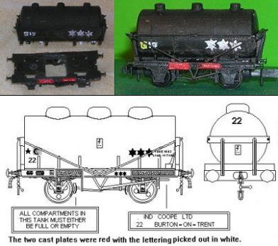 |
|
APOC twin tank wagon from the Peco kit  This one is rather a case of do as I say not as I did. I tried to cut a 3mm section from the centre of the Peco tank, ending up with two rather short half sections. I ended up having to use three layers of 40 thou card to build up the tank ends. I also made the filling domes too tall and hence the top mounted valves too tall as well. The domes or hatches should be no more than 1mm above the tank top with the valve handle a couple of mm above them. To make this wagon use a razor saw to cut off the tank top details (filling dome and platforms), if you end up with a notch in the tank top fill this with microstrip and set aside to dry, then file it smooth and file away the tank side rails. Now cut down through the centre of the tank (use the hole for the ladder as a guide), you can use a hacksaw for this as precision is not essential. Now rub the open ends of the tanks on a sheet of sand paper until you have a 4mm gap between the half sections when on the cradle. If you keep going until the holes for the ladders are no longer there you should be about right. The tank is heavy enough not to require any additional weight inside. Add a rectangle of 40 thou card to each open end, trim this roughly with scissors then trim it close using toe nail clippers. Sand the card to form a 'domed' end, this takes time. The filler domes on the model are cut from round section sprue, the valve handles are dress making pins, the Peco body is very thick so I had to hold a pin in pliers, heat it over a candle and burn a hole with this to take the 'valves'. I added strips of cigarette paper round the base of the 'valve spindles', if your patience and eyesight are up to it you can fold a strip of paper, punch through the fold with the pin then trim the paper - With the pin in the hole trim the paper to a thin strip, fold the ends down beside the pin and cut to 2mm long. This gives a good representation of the bracket holding the valve spindle, I did it once, it took me ages and for my own model I couldn't be bothered. The original tank had pipes on the end as shown in the sketch, with a matt black paint job these are effectively invisible but I added a strip across the lower part of the end cradle to represent the upper cross pipe. The ends of the Peco tank are also very thick so if you plan to use wire you would need to mark the ends (whilst in the cradle) then melt the holes with a hot pin. Adding short lengths of 1mm rod with 10 or 20 thou rod across between them would be easier, as I say with a black paint job these are not really visible under normal conditions and can be omitted, if you plan heavy weathering it might be worth adding them. Trim off the side cradle extensions at each end of the frame leaving the inner set in place. Mount the two tank sections on the cradle and add a 2mm length of 40 thou between them in the centre. Mount the cradle on the chassis (not forgetting the couplings and check the couplings are okay (on these tank kits I find I have to sand down the wagon chassis and the bottom of the cradle a bit to avoid droopy couplings). If all is well add the supplied wire end stays and fix with the supplied securing nuts. Cut eight lengths of 40x40 thou strip about 10-15mm long, cut a slanted end of four of them and glue these to the uncut lengths. When set add these to the tank sides, set in from the tank ends and matching the existing inner cradles. I would suggest using Slaters 20 thou brass wire for the side rails, I didn't have any with me when I made this one so I used 20x20 thou plastic strip, again as it is painted black you can get away with this. The Anglo Persian Oil Corporation became BP in the 1920s, although the APOC livery may have remained in use into the 1930s. My livery is from a photo taken in the 1980s, showing the tattered remains of the 1950s BR era livery, by which time these tanks had been sold to a lubricant manufacturer. They were overpainted plain black and the lettering consisted of a return-to marking and a three digit number, the tanks also had an A and B markings (not apparent on the APOC livery). These wagons did not qualify for a fast traffic star. By the 1980s the paint was wearing off and the A and C of the original markings (in line with the filler domes) were partly revealed, by this time they were 'internal use only' vehicles. My 'lettering' was added using a rollerball white pen from a stationers, these are a bit thick but the ink resists weathering with dirty thinners. 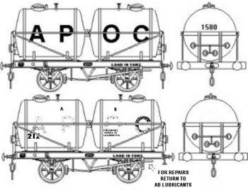 If you cut away the centre section of the Peco chassis you get a better representation of the open chassis used for tank wagons, sanding the edges down toward the top helps keep the side members down to a reasonable thickness. The Peco wires run across the gap but in practice these are not noticeable and I did not feel like cutting them back and super-gluing them to the chassis sides. The photo shows the twin tank wagon and an unmodified RTR Peco tank. 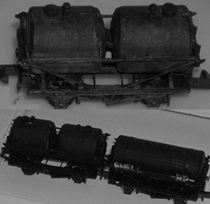 You can if you wish add the straps holding down the tank, use strips of parcel tape across the top of the tank and 10x20 thou strip from the side rail down to the chassis. I did this once and found that on a black tank they were (to me) invisible so I didn't bother with this model. |
|
Vintage 'Class A' bogie tank wagon made using the Peco kit This tank wagon was built in 1929, it also featured on the British Railways Model Railway (built as a promotional model in about 1950), suggesting it was still in use in the early BR era. My model was made shortly after the Peco tank wagon kit first appeared, I used too much glue which caused the chassis to warp slightly. The model was built for the god son's layout so I did not add trussing as I thought this would get broken. I later found out that the trussing on the prototype was removed soon after it was built, the model as shown is (in that regard) accurate. He had no practical use for a Class A tank on his branch line layout so the model was liveried as a Class B tank, transporting fuel oil to the docks. The name on the side is from a Woodhead Models wagon-side coal wagon transfer. 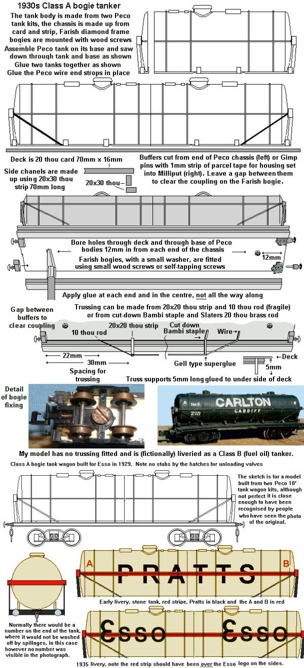 |
|
|
Early Private Owner anchor mounted tank wagon This model is based on a Shell BP tank built in 1901 and finally retired (into preservation) in the 1960s. The body is a scrap of tube 13mm in diameter and slightly too short (I should have built up the ends with additional layers of 30 thou card). I had to use super glue to stick anything to this tube so I used a spare W&T filling hatch (which I think looks a bit tall). The weight inside the tank is two crushed air gun pellets fixed with superglue. The ends are two layers of 30 thou card sanded to a dome shape, the side supports are 20 thou card 4mm high, glued to the chassis with solvent (which holds them in place but allows final adjustment) then super-glued to the tank body. The prototype had a ten foot wheelbase so I used a Peco chassis kit, I cut the plugs from the coupling retainers and glued them in place. I cut away the square central section of the chassis, sanding the top of the inner sides to an angle to reduce the thickness, to represent the open framed construction of a tank wagon chassis. I added a 3mm strip of 30 thou to the centre of the under side with another length cut to length on top sitting in the central hole to represent the longitudinal chassis members. The tank barrel was glued to the chassis and this strip. The model shown has been repainted as the original Shell BP livery is to be replaced by a fictitious livery used on the layout. 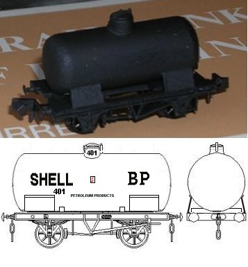 If using Evergreen 12.7mm tube you should add a strip of 10x20 thou to the tank where it meets the anchor plate as the plate was bent at an angle and riveted to the tank. I could not do this because of the type of plastic I used for the barrel. In practice these anchor mounted tanks are very easy models to make and there are a number of anchor mounted tank types of possible interest to the pre-grouping and pre-nationalisation modeller. Many of these tanks survived into BR ownership, elderly PO tanks were commonplace in mixed goods trains until the mid 1960s when the newer types of high capacity tanks and high speed block trains began to take over. The basic method of producing the model would be the same for each, only the size and number of anchor plates would alter. | |
Acid and chlorine tanks Acids and chemicals such as chlorine weigh more than many oils and were used in smaller quantities for many applications. As a result the tanks used for these duties tended to be smaller, typically about five feet or so in diameter. These tanks can be conveniently modelled using Plastruct tube TBFS12 (9.5mm in diameter). A typical acid tank would be about a foot shorter than the chassis (a Peco 9' or 10' wheelbase chassis can be used), my model has a full length tank as this makes the ends easier to model. The photo shows the model alongside a standard Peco tank. 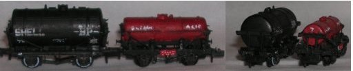 The barrel is a length of TBFS12 tube, the ends are two layers of 30 thou card glued to the end of the tube and trimmed to shape using toe nail clippers then sanded down to form the dome shape required. The end supports (on my model) are made from strip, with a 40x40 thou strip across the centre supported on two strips of 30x30 thou, all glued to the tank end. The end supports should be left extending below the tank as the tank is supported on four cross-bars made from 40x40 thou strip. On the model you add a strip across each end (on the 9' wheelbase chassis this runs across the centre of the coupling pocket) and two toward the centre (mine run across the ends of the Peco brake gear, I sanded these down toward the top before adding the strips to open up the chassis and give a more see-through look). Trim the end supports on the tank to length and glue the tank to the chassis cross-beams. When set cut eight 1" lengths of 40x40 thou strip and trim one end at an angle. These are glued on top of the cross-beans with the trimmed end tucked in under the tank side. When dry the cross-beams can be trimmed to length using toe nail clippers. The filling dome on my model is (I think) one cut from the top of a Peco tank wagon but you can use round section sprue, adding detail if required using 10x10 thou strip. The small vent beside it is a Peco track pin fitted in a hole in the top of the tank. The horizontal bar along the tank side and the diagonal strops are all 20 thou brass rod. The original ICI chlorine tanks were odd looking vehicles, they had a 10'6" wheelbase but a chassis about 20" long. Fortunately the Peco 15' wheelbase chassis can be used to model this chassis. This is made as for the 'unfitted' 12' wheelbase chassis described in section A, but with 11mm cut from the centre of the chassis. There were also some similar tanks on a 12' wheelbase chassis (former acid tanks) converted for chlorine traffic. 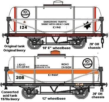 For the 12' wheelbase chassis you can use either a Parkside Dundas chassis or a Peco 15' wheelbase chassis cut down as shown in section A. The 10'6" wheelbase chassis can also be made from the Peco 15' wheelbase chassis. Cut down the Peco chassis and assemble as described in section A. Trim the plugs from the supplied Peco coupling retainers and fit these, ensuring the couplings are level before washing them over with glue. Glue four lengths of 40x40 thou strip across the chassis. Measure the chassis and cut a length of tube which is 6mm shorter than the chassis, add ends from three layers of 30 thou (three layers are needed to allow you to sand the end to a more domed shape than a liquid tank). Glue the tank in position on the chassis and add the cross-bars to the tank ends from 40x40 thou strip. The T section end supports can be made up from 10x20 thou strip with a length of 10x10 thou run up the centre of one side, or you can use the smallest T section strip in the Plastruct fineline counter display box. The horizontal tank side bar and diagonal end strops are all from 20 thou brass rod. Find the centre of the top of the tank and make saw cuts 4mm to either side, running across the tank. Lay cross-strips into these, I used 2mm wide strips of 10 thou from a packet of mixed microstrip, so my slots were 2mm deep. The filler dome is made from tube or rodding, this should be about 2.5-3mm in diameter, if tube is used fill the inside with Milliput. Cut a rectangle of 20 thou card 8mm square, draw pencil lines across this to mark the centre and bore a hole in this until the tube is a push-fit in the hole. Sand the end of the tube to a dome shape and push through the plate until 2mm is showing above the top. Trim the tube flush with the bottom of the plate and glue this in position on the cross-bars atop the tank.  |
|
Early non pressurised BR ferry chemical tank. The sketch shows a BR built chemical tank to dia 1/305, these were leased to a private owner and initially used for benzene traffic, the original livery had black solebars, the red came later. It is essentially a standard BR 20 ton Class A tanker but with ferry chain points on the chassis and a 'ferry plate' on the left hand end of the solebars. Benzene is a colourless flammable liquid, prior to world war two it was mainly obtained from coal (a by product of coke works) but after the war it was increasingly produced from oil. It is used in pesticides and in a number of solvents used by (amongst others) paper manufacturers. It is also used in the manufacture of phenol, toluene, aniline, naphthalene and anthracene. Prior to world war one it was widely used as an after-shave, by the 1920s it was a widely used solvent and in the early forms of decaffeinated coffee - As it is somewhat toxic all of these uses were discontinued by the later 1930s. By that time it was a widely used additive for petrol and remained popular until the 1950s when tetraethyl lead replaced it, now that the lead is banned petrol again contains small quantities of benzene. The main use for benzene is in the manufacture of other chemicals whilst some is used in lubricants, dyes, detergents, drugs, explosives and pesticides. In later years these tanks carried a range of chemicals including propylene oxide (nasty stuff that, produced in oil refineries and used in plastics manufacture, mainly for soft foams used in upholstery but also for hard plastics such as those used for bowling balls). The upper sketch shows the original as-delivered livery, I believe this changed in the mid 1950s to all-over white tank with TRAFFIC SERVICES LIMITED along the sides in black (the tank may have been blue), by the mid 1960s the tanks were definitely all blue, they had added the logo and reduced LIMITED to Ltd on the sides. TSL became part of Tiger Railcars in 1976 but the use of the logo (without the words) seems to have continued into the early 1980s at least. The lower example shown was still in the basic TSL blue and with the logo but with the ferry plate also painted blue with white working instructions with an indicated cargo of sodium metasilicate, suggesting it was no longer in ferry use. The TSL logo seems to have been plain black and white (in the days when the tanks had the words as well this was coloured as described in the Operations section under grain traffic) and at some point two fast traffic stars had been added to the livery which had faded in departmental use. Sodium metasilicate is a sodium salt, in this case dissolved in water, used in a wide range of industrial cleaning agents, this may well have been the last cargo it carried as a PO tank. By the mid 1980s several of these tanks were departmental vehicles coded ZRR under TOPS, the blue tank shown below was actually in departmental service when photographed. Other examples of this tank were in a plain all over grey or light blue livery, some with DIVISIONAL ENGINEER in white on a black patch where the TSL logo had been, others (having been repainted) with writing on the tank on the lines of 'DCE NORWICH - WATER ONLY - RETURN TO WENSHAM' in three lines one above the other on the left hand end of the tank. Most still retained the 'ferry plate' on the left hand end of the solebar and most had a new ladder on one side only, with no walkway round the filler cap. They all seemed to have acquired red solebars at some point, a few still had these in their engineers guise although they were carrying water. 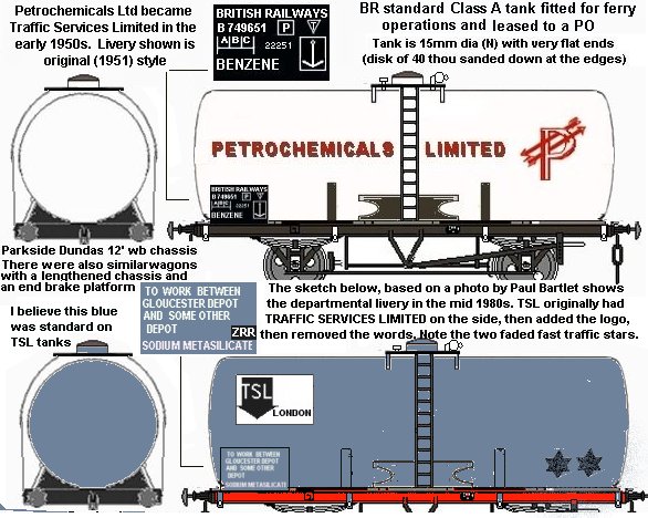 The chassis can be a cut down Peco 15' wheelbase chassis (as described in Section A) or a Parkside Dundas chassis (the latter looks better but is slightly problematic as it is more difficult to fit the tank securing parts on the open Parkside chassis). The body is 15mm diameter tube, if you are lucky a local shop with have 15mm diameter polystyrene till roll centres, if not you can use 15mm cable conduit from the local hardware shop (you will need to use Superglue with this latter). Cut a section 41mm long and glue a rectangle of 40 thou card to each end (if using polystyrene do not forget to drill a 'breather' hole in the bottom of the tank). Use toe nail clippers to trim the card to the tank ends and finish with sand paper. The end was slightly domed so use a sandpaper nail file to trim the end down to something like a shallow cone, then round this off to make the dome. Cut two slots in the base of the tank 5mm deep and 17mm apart and fit strips of 20 thou card 5mm wide into these. Trim the ends to the width of the chassis, near vertical but angled inwards slightly toward the tank. Add a 1mm strip of 10 or 20 thou to form a T shaped outer edge to the support. Glue the tank to the chassis. To make the side anchor plates use a leather punch to make two holes 2mm diameter and 7mm apart, then cut this area out to as a 3mm high strip and trim to the shape as shown (the bottom bit is 11mm long, the top is 10mm long). These are glued at an angle of about 45 degrees between the tank side and the chassis, the notched ends can be held with long nosed pliers to fit. Sand the end of a piece of 3 or 4mm diameter tube to fit the curve of the tank, cut off a 2mm length of this and glue it centrally on the tank top and fill the centre with Milliput. There is a filling valve to one side, for which 1mm diameter wire (florists iron wire will do for this in N) bent into an L shape and fixed in a hole bored in the tank top will do. On the other side was a vent, for which the top few mm of a dress making pin, set into a hole in the tank with 2mm showing, will do. When all this has set use a razor saw to make two cuts across the top of the tank 13mm apart evenly spaced either side of the filling dome. These cuts should be about 1.5mm deep. Slaters assorted plastic strip includes strips 2mm wide of 10 thou, glue an inch or so of this into each slot. Take some 20thou card and cut a strip about 2.5mm wide, squeeze this between serrated pliers to 'emboss' the surface and glue two 10mm strips of this 'chequerplate' to the top of the cross strips. Trim the transverse 'platform supports' to length. Add a ladder, signal ladder is good for this, brass for preference (for one thing it is easier to bend and it looks a lot better). The 'ferry plate' is a rectangle of 20 thou card 6mm long by 5mm high, these are at the left hand end on each side. |
|
Chemical gas tanks made using the W & T oil tank kit The W & T oil tank kit consists of cast metal ends with a length of plastic tube, it is designed to fit the Peco 10 foot wheelbase chassis and has the coupling retaining pins moulded onto the base. The kits are now sold by Scalelink and if you ask when ordering they will supply a length of un-cut tube. This kit is very handy for making all sorts of 'lagged' (smooth walled) tank wagons but it is made of a plastic that my polystyrene solvent would not stick, superglue works well. The tube is 12mm in diameter, corresponding to 1.9m or 5'10" in British N, slightly small for some tank types and too large for others. 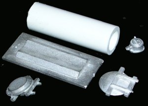 I bought mine just before the Peco tank appeared, and I prefer the look of the Peco 16 ton tank for my early BR era layout. The W&T model looks like a 14 (possibly 12) tonner to my eye. Although 1mm too large it does not look too bad for the BR built chemical ferry tanks although the ends are not as bowed out as the prototype. These white tanks all show up rather well in long rakes of the rather more mundane British railway liveries and they can be run on continental as well as British outline layouts. The red bands at either end of the tank lend themselves to the use of a paper wrapper for the tank barrel, the plain white livery is also a help as you do not have the problem of matching the colour of the ends. The Parkside Dundas chassis can be used for some of the 12' wheelbase types, but I would suggest using a cut-down Peco 15' wheelbase chassis for the BR built ferry chlorine tanks at least as the ends are rather shorter than a standard chassis. The original chassis on the BR tank was slightly shorter than a standard 12' wheelbase type, being only 40mm long in N. Most of my 12' wheelbase conversions end up closer to 45mm, but you can cut through the chassis close by the coupling pocket and again between the outer brake shoes and the ends of the springs to reduce the length of each end by about 2mm. Alternatively you can opt for an under length wheelbase but that looks wrong, as does an over-long tank. |
|
ICI Arcton Tank Not all tanks were the full length of the chassis, some tanks had a shorter barrel with inward angled end supports and several ferry equipped tanks had a platform at one end, usually with a hand rail and a brake wheel mounted on it. The example shown below was operating on the 1960s It has a 14' 10" wheelbase chassis, there is a platform with hand rail at one end and I believe the other end was inset slightly as shown. My model was based on a photo in an article on ferry stock in the 1985 Model Railway Constructor annual. Arcton was a widely used refrigerant, one of the CFC family, it was manufactured at Runcorn in Cheshire so these tanks might be seen anywhere in the UK as well as on the route to Harwich for ferry links to the continent. 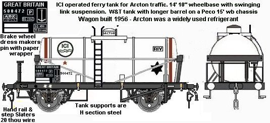 To save making the steps I cut the end from a Peco long wheelbase brake van, just inboard of the second step support (this cuts through the brake shoe). I then used this to mark the chassis and cut away the same section. The brake van end, with steps, was then grafted onto the remainder of the tanker chassis (having sanded the top of everything flat first). When the two parts have set check the wheels fit comfortably, I had to do a little carving to clear the brake shoes on the steps end. I cut away the chassis between the wheel holes, leaving each side and the central strip in place and sanded away the outer top edge to leave a narrow solebar. This made fitting the side supports more difficult so you can skip that bit if you wish. For my model I used a piece of W&T tube of 37mm, I would suggest aiming for 38mm then test fit the ends and sand the tube until these are at right angles to the tank body and in line with each other. Fix the ends with Superglue (you can do this with them in place). The wagon has a platform with hand rail and brake wheel at one end and a smaller platform at the other. I cut one end of the W&T tank base where the tank support starts (about 4mm from the end), this was used for the shorter end, for the longer (brake platform) end I cut 7mm from the supplied base. With a little sanding of the underside these work with the Peco couplings. I used superglue to fix the tank base ends to the chassis having sanded them to get the couplings level. I used a saw to make three cuts in the platform end, one each side just outboard of the buffers about 1mm deep, one just inboard of the buffers about 2mm deep. I glued a cut down dressmaking pin in the inner slot to represent the brake wheel (on my model this is on the wrong side, it should be on the ladder side of the wagon) and a U shaped length of Slaters 20 thou brass wire into the outer slots for the handrail (this should 'dip' at the brake wheel end as shown in the sketch, mine is flat). Superglue holds the brake wheel and handrail in place. I added a short strip of 40x40 thou across the central strip of the chassis, this allows the centre of the tank to be superglued down later. Take the tank and add the horizontal rails along the sides, I used 20 thou rod superglued to the tube. I did not bother with the over the tank strips, if you wish these can be added using strips of masking tape over the top half of the tanks with the lower part represented by 10x20 thou strip, but remember this is difficult to glue to the W&T tube. Sand and scrape (using a knife held at right angles to the surface) a flat in the centre of the top of the tank, this should be 10mm long and about 10 thou deep. Cut a rectangle of 20 thou card 10mm by 10mm, scribe this in a cross hatch pattern with the tip of your knife to represent 'chequer plate' and glue into the flat recess. Cut strips of 20 thou 10mm wide and sand one end until these form a close fit against the tank under the top plate, glue to the top plate then (when dry) trim and sand the outer edges smooth. This gives you the rather deep platform as on the prototype. Sand the base of the supplied filler dome flat and glue this to the centre of the resulting platform. The tank end supports have small bits that are designed to extend down across the buffer beam, trim these away to get a flat base. Now check the tank for a close fit at either end between the white metal tank base parts. File the outside ends of the base of the tank end supports down to achieve a good fit, this leaves the tank supported on the ends and sitting about 1mm above the chassis. Now is the time to paint and letter the tank barrel, I used white paint for the body and ends, red paint for the stripes and a black laundry marker for the markings (give the white paint 24 hours to dry before using the marker pen or it will just clog with paint). Once happy glue the tank assembly to the chassis with superglue. The tank side supports can be Plastruct H section or you can make up H section from strip, trim to fit and glue to the chassis with solvent, when set add a touch of superglue to the tank end using a cocktail stick. I used sections cut from plastic tube, cut to form an L shape with the base of the L sanded as thin as I could to make a good joint for gluing to the tank. When everything is set touch up the white paint to get rid of any shiny superglue deposits on the matt white tank. The ladder is on one side only, etched brass looks best but plastic will do if it is all you have. The ladder that comes with a standard Peco 10' wheelbase tank fits neatly with the top superglued under the platform and the mounting peg superglued to the tank just below the hand rail. You only need trim off the bottom filled-in square on the ladder and glue the bottom end to the chassis. The prototype had two 'horns' at the top of the ladder, unusual on British stock, if you want to add these (very fragile items) you can trim the steps from brass laddering but for plastic ladders add the 'horns' using Slaters wire bent into an L shape and glued to the underside of the chequer plate. I did not bother. The diagonal straps on the sides are 20 thou brass wire, use a saw to cut slots into the chassis sides and superglue the wire into the slots and onto the tank end cross-bar. The 'ferry' plate is a rectangle of 20 thou card glued to the chassis, you can use a computer printer to make the markings and stick this to the card with Bostick. I used a mapping pen and Windsor and Newton white ink - You need to leave the paint to dry for 24 hours before adding the lettering or it just clogs the pen. 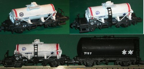 My model is less than perfect, I was working from memory and with a few hasty sketches as I could not carry all my books with me when traveling. The end handrail is not the right shape, the hand wheel is on the wrong side and the tank supports are not H section, however it rolls well and looks close enough to satisfy my needs. The markings on the tank are fine tipped black laundry marker, the markings on the 'ferry plate' and chassis were done with a mapping pen and white ink but the lettering is just dots. The bottom picture shows the tank against a standard Peco tank on the same chassis, these early pressurised tanks were heavily built but even so arcton is evidently heavy stuff. I found a picture of the Arcton storage tanks at the ICI plant in Runcorn on Graham Davies website, which Graham has kindly allowed me to use here. 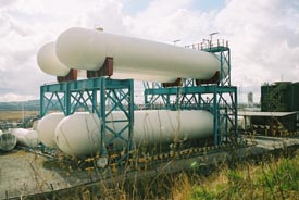 | |
BR built ferry equipped pressurised gas (chemical) tanks Built in 1950 as dia 1/301 these 14 ton wagons were owned by BR and leased to Petrochemicals Limited, used for ferry traffic to the Continent. The tank on this wagon should be about 11mm in diameter, it should be 39mm long on a 40mm long chassis, but all depends on the size of the chassis you use. The end supports are vertical T section (not inclined outwards as for example on the Peco 10' wheelbase tank, the W&T tank ends do have vertical end supports) but a cheaper model can be made using Evergreen 11.1mm tube with the end built up of 2 layers of 30 thou sanded to shape and Plastruct T section end supports with a 1.5mm high 40 thou thick cross timber. The vehicle is 'piped' for vacuum and air brake as it was for ferry use. In 1952 they got a sun shield (a strip of 20 thou card is good for this, sand the outer edge so it looks like thin metal supported off the tank body. If using computer sticky labels for the livery make an extra section for the sun shield) which also boxed-in the platform as shown. 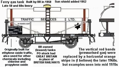 Built for ethylene oxide traffic apparently these tanks carried a range of cargo over the years including liquid chlorine but ended up back on ethylene oxide traffic. Ethylene oxide (EtO) is a colourless gas widely used to sterilize substances that would be damaged by sterilizing techniques such as pasteurization that rely on heat. Ethylene oxide sterilization for the preservation of spices was patented in 1938 by the American chemist Lloyd Hall. It is also used to make other chemicals, notably ethylene glycol, as well as detergents, solvents and adhesives, among others. One cargo for these tanks was Butadiene, a chemical that came to prominence in the lead up to world war two for the production of synthetic rubber, which remains the main use (most car tyres are made of styrene-butadiene rubber, and ABS plastic is based on butadiene). Butadiene is also used in the manufacture of nylon and a number of other chemicals. By the 1960s several of these tanks were being used for dangerous or inflammable cargo and had red solebars. By the 1970s the plate on the left hand end was all red and marked as shown below (indicating they were no longer in ferry use and some at least were carrying chlorine again). 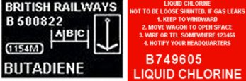 These tanks were briefly described article on ferry stock in the 1985 Model Railway Constructor annual which notes that some had ended up as water tanks for the engineers on Eastern Region by the 1980s. | |
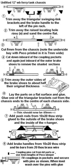
The model is not difficult to make, although mine is a poor example. The Peco chassis needs to be altered rather a lot but this works as I have built several wagons using similar methods. Trim the triangular swinging link suspension brackets fro the chassis (carefully) and keep these on one side. Now with the chassis on its back cut down through just behind the coupling pockets, leaving you with two short ends. Now cut down between the outer brake shoe and the wheel support, removing a section from each end. Finally remove a 7mm section from the centre of the chassis. Lay the two main chassis sections on a flat surface (glazed tile, I use the Xacto mitre box upside down) and apply glue to the joint. Push together and move the assembly about (or it tends to stick to the surface of the tile). After a few second the glue should have gone off enough to let go. Now take the ends with the coupling pockets and glue these to the chassis ends in the same way. This should give you a chassis with a 12' wheelbase but an overall length of about 40mm. Assemble the tank using a 37mm section of tube with the supplied ends, you need to use superglue for this. When set sand the base of the ends down until they are flush with the base of the tank (this reduces the overall height and gets it to about right for the prototype). Cut a strip of 20 thou 13mm x 38mm, use a pencil to mark across from corner to corner to find the centre. For the filling dome you will need some tube 3mm or thereabouts in diameter, I used plastic drinking straw filled with Milliput. Use a pointed modelling knife to bore a hole in the centre of the sheet until it is a push-fit onto the tube. Now find something round of about 12mm diameter (I used the handle of a wooden spoon but a craft knife would do) lay the strip against this and, keeping the strip parallel, wind string tightly round it to pull it to shape. Place this assembly in a cup and pour in boiling water from the kettle. Leave for a few minutes, empty the water and again add boiling water. Leave to cool off. Cut a rectangle of 20 thou card 10mm x 10mm, scribe the top with cross-hatched lines to represent 'tread plate'. Mark the centre (by drawing lines across from corner to corner) and bore a hole that is a push fit for the tube used for the filling dome. On the tank mark the top centre and bore a hole for the plastic tube, again this should be a push-fit. Cut the tube to be used for the filler dome to about 10mm long and insert this in the top plate (ensuring the cross hatching is on top). By now the curved strip should have cooled down, and you should find it is a comfortable fit on the tank top. Push the tube down through the strip and then into the hole on the tank top. I think I used Bostick to attach the 'sun shield' strip to the tank. Adjust the 'filler dome' so about 2mm shows above the top of the plate and glue the square plate square on the top of the sun shield and set the tank assembly aside to set. When set sand the 'dome' to more of a dome shape. Add the side rails to the tank using Slaters 20 thou rod attached with Superglue, these should be level with the lower edge of the tank end cross-beams to leave space for the company name. At this point paint the body of the tank with white paint and set aside to dry (give it a 24 hour drying time so the enamel sets properly). Do not paint the chassis at this time. The brake gear on the chassis can be represented using the triangular swinging link parts for the V hanger with 10x20 thou strip for the push rods and brake handle. You need to trim away the outer face of the brake shoes to about half their original thickness so the push-rod strip lies across the back of the V hanger and the front of the brake shoes. The tie-bar between the axle boxes is Slaters 20 thou rod fitted with superglue (there is a slight 'notch' in the moulding, if you squeeze gently you can push the wire into this). I have some 20 year old wagons with these tie-rods and none have come loose. Cut the plastic coupling plugs from the Peco kit pins and insert these with the couplings, adjust until the couplings are level and wash with glue to hold them in place. I added the fast traffic star and company name to the tank using a laundry pen, I was in a hot climate so the ink was rather runny and the lettering came out a bit thick, so I later gave it a wash with a trace of white to tone it down. The other lettering on my tanks is just dots. For the company name you could print them using a computer, either onto peel-off labels or plain paper (attached with Bostic or similar), this would give a much better look than mine and as the name is framed by the sun shield and the tank side rail the thickness of the paper will not show. Add the red stripes around each end of the tank. When happy with the lettering glue the tank centrally to the chassis, I used Superglue for this. Now glue two lengths of 40x40 thou strip together to form an 80x40 thou strip. Cut through this at about one inch intervals at a sharp angle, you need six or eight (see below) lengths each with at least one angled end. Glue these to the chassis with the angle pushed under the tank side to form the cross-supports, I did not add one where the 'ferry plate would be on the left because of the way I planned to fit this, if using 20 thou card for the ferry plate add the cross bar to the left hand end as this will support the plate. Once these are set trim them back using toe nail clippers. Use a razor saw to cut diagonal slots in the chassis in line with the tank end cross-bars and add the diagonal bracing from 20 thou brass rod (I added a slight bend to the top end so it 'hooked' onto the top of the cross-bar, this make it more secure and does not show up too badly once the paint is touched up). Glue the rod to the end cross-bar and into the slots on the chassis using Superglue. For the ferry plate you can use a rectangle of 20 thou card 5mm long by 4mm high. I cut down some 4mm square tube to form L shaped sections, gluing one to the left hand end of each chassis. It helps to paint the rear of the ferry plate black before attaching to the chassis. Now add the ladders, preferably from etched brass signal laddering, bend the top end and glue this under the platform, glue to the side rail and to the chassis all with superglue. If using ladders from the Peco tanker the top will need trimming until the middle support pin lies just under the side rail on the tank, the base is then trimmed to lie against but not below the chassis, fix with Superglue. When everything is set fill in the underside of the top plate with Milliput, smoothing this with an old modelling knife blade (wet this to get a smooth finish). Set aside to dry and set. When everything has set touch up the paint job, the diagonal rods should be white and the ladder black. Now paint the chassis, in my case the cargo was butadiene (correct for the later 1950s for some tanks at least) and hence I have red solebars on the chassis (indicating an inflammable cargo). The ferry plate is black with white markings added using a mapping pen and ink. 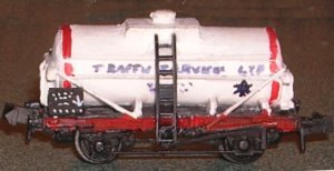 |
 |