Appendix Four - Locomotives
Overview and General Information
NB The sketches used for illustration are NOT scale drawings. I am deeply indebted to the members of the uk.railway and uk.rec.models.rail newsgroups who have provided a great deal of the information for this appendix.
Note There is a fore-shortening effect when a locomotive is viewed from the normal 'three quarter view' angle, making it appear rather shorter than it is. The photo below shows this effect. When preparing sketches I have tried to find photographs to work from taken at as flat an angle as I was able.
Model of an LNER Class A1 locomotive 'Flying Scotsman'
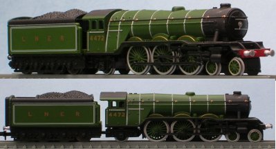
Photo of model courtesy Ian and Sandra Franz
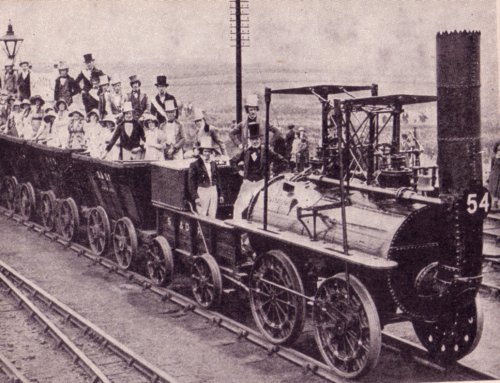
The first steam locomotives used in collieries and the like were based on the 'beam engine', they had vertical cylinders driving one end of a rocking arm or beam, the other end was connected to a crank attached to the wheels. These machines were slow and not very efficient but at a time of rising fodder prices they offered some advantages over the horse. An early success was Locomotion No.1 on the Stockton and Darlington line opened in 1825, derived from colliery engine practice this used a moderately high pressure boiler driving the pistons in vertically mounted cylinders with cross beams driving the wheels using coupling rods. The photo below was scanned from a book published in the 1930s, the photo was taken at the Centinery exhibition on the line in 1929 and shows a replica engine built for the occasion which proved capable of speeds of up to 12 miles per hour when pulling a full load. The telegraph pole with its bank of insulators would not have been present when the original engine was in service.
Locomotion No.1 replica on the Stockton and Darlington line
The building of the Liverpool and Manchester Railway provided the impetus for development, fixed engines hauling wagons by cable and even horses were considered for this line so the steam locomotive needed to demonstrate its superiority. By this time there had been a number of developments, boilers now had many small tubes to carry the hot gasses from the firebox which increased the heating surface considerably, also the exhaust steam from the cylinders was directed into the smoke box at the front of the boiler, blowing upwards across the ends of the boiler tubes and drawing the hot gasses through the boiler more efficiently. Finally the cylinders themselves were bored out not cast, allowing a much tighter fit on the pistons and increasing the efficiency. The Rocket won the trials for the L&M line and incorporated all these features.
The Rocket had a pair of large wheels at the front, driven by the pistons, and a pair of smaller, non powered wheels at the rear. The wheels were fixed to the chassis but as the wheelbase was so short this caused no problems even on very tight curves.
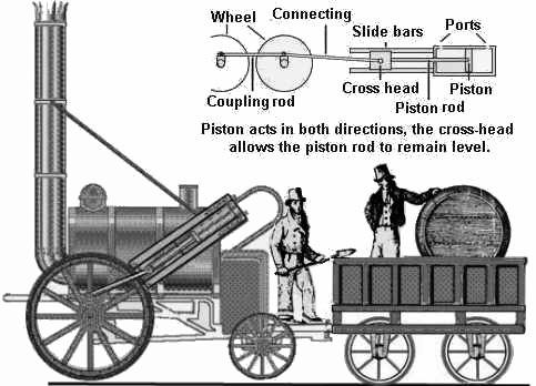
Fig___ The Rocket of 1830
All locomotives of the early period ran on coke, which produced more heat and less soot, from the later 19th century coal came into use as the technical problems of getting it to burn hot enough were solved and supplies of suitable coal were identified (notably Welsh 'steam coal', very little ash and a lot of heat produced).
The early boilers were made of riveted plates of wrought iron, which corroded in the hot and often poluted water and regularly exploded. The boilers were fitted with a simple safety valve, controlled by a spring however the spring tension could be adjusted but there was no indication on the valve saying what pressure it was set for. Only in 1849 did the government pass a law requiring proper pressure testing of boilers and the fitting of pressure gauges.
Quartering
If a steam engine with only one cylinder stops with the piston right at the end of its travel you have no way of knowing which way the wheels will turn when the engine starts. For this reason steam locomotives always had at least two cylinders and the cranks were arranged so that when one cylinder was at the end of its travel the other was part-way along, for balancing this was arranged so that the cranks on opposite wheels were set at 90 degrees.
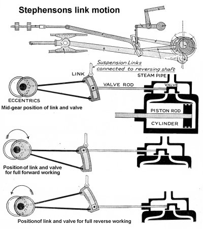
Slide valves and reversing gear
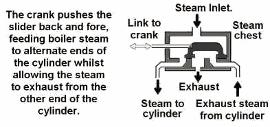
Steam engines use a simple device called a 'slide valve' mounted on the cylinder to allow steam into one end of the cylinder and allow exhaust steam out at the other end.
Fig___ Steam engine slide valve
Usually the slide valve formed part of the cylinder casting, looking like a small cylinder mounted on top of the actual driving cylinder but with nothing connecting it to the wheels.
The slide valve is linked to the engine by a crank, on a locomotive this can conveniently be fitted to the cross head on the piston rod. To reverse the engine all that is required is a device to alter the position of the valve relative to the position of the piston which is easily done using a simple linkage controlled from the cab using a lever. This also allows the driver to control the point at which the supply of steam is cut off from the cylinder, normally only when starting the locomotive is steam fed in for the entire stroke, once running it is much more economical to cut the steam off early, allowing it to expand inside the cylinder for the latter part of the stroke. One of the oldest, and simplest, reversing gear options is Stevenson's Link Gear which was operated by a lever in the engine cab via a long rod extending down along the length of the boiler toward the cylinders.
Fig___ Stephenson's Link Motion
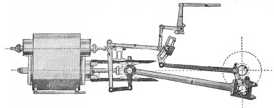
A rather more visually complicated arrangement (although requiring only a single eccentric), which offers some technical advantages in the control of the flow of steam, is the Walschaerts valve gear (technically one of a family of devices called 'radial valve gears'). Walschaerts valve gear was widely used on steam locomotives on the continent, less so on pre nationalisation British engines but standard on the BR standard engine designs, and is recognisable by the plethora of rods and levers running between the wheel and the piston casing containing the slide valve.
Fig___ Walschaerts valve gear
Whyte Notation
It is usual to describe a steam or diesel loco by listing the wheel
arrangement. In Britain we normally use the 'Whyte Notation', which in the case
of the steam loco divides the wheels into three groups: the driving wheels in
the centre and un-powered wheels at the front or rear of the loco.
Taking the Minitrix Britannia as an example there is a 'bogie'
with four wheels at the front, this was provided to help guide the loco into
curves and to support a longer boiler. At the rear there is a similar truck, in
this case with two wheels but on some loco's with four, which supported the
weight of the brick-lined fire box. In between are the six large driving
wheels connected to the cylinders. This would be described as a 4-6-2 loco in
Whyte notation.
Locomotive Names
Locomotives were expensive items of equipment and were often
named, especially passenger loco's but with the smaller companies all the
locomotives might be named. The name given to the first of a particular design
or class was usually used as a general term to identify similar loco's. As an
example 'Britannia' was the first of a standard British Railways 4-6-2 design
steam loco, and similar locomotives were commonly known as 'Britannia's'. You
may also hear a locomotive being described as a 'Mogul' or as a 'Pacific' ,
these are the American terms for 2-6-0 and 4-6-2 wheel arrangements. These
American terms became popular in the UK and the following is a list of the more
common:
Freight Loco's
oOOO 2-6-0 Mogul
oOOOO
2-8-0 Consolidation
oOOOOo 2-8-2 Mikado
oOOOOO 2-10-0 Decapod
oOOOOOo 2-10-2 Santa Fe
In the UK there was a single example
of an 0-10-0 steam tank loco built by the North Eastern Railway and named
'Decapod' (note this was the engine name not the wheel arrangement) which was built to prove a steam loco could accelerate as well as the
new electric trains in London. The only other 0-10-0 engines I know of iun the UK was the single big banking engine built by the Midland Railway for work on the Lickey Incline, where they pushed heavy trains from behind to assist them up the hill. They built two boilers for this engine to reduce the 'down time' should there ever be a prolem with it, the photo below was scanned from a 1930s book on engineering.
Fig___ The classic banking engine in LMS livery
The 0-6-0 configuration favoured by the
British for goods work was only used on small shunting loco's in the USA, they
were commonly called 'switchers' but this term was applied to any loco used for
these duties regardless of wheel arrangement.
Passenger Loco's
ooO 4-2-0 Crompton or National
ooOO 4-4-0 American
ooOO0 4-4-2 Atlantic
oOOOo 2-6-2 Prairie
ooOOOo 4-6-2
Pacific
ooOOOoo 4-6-4 Baltic
ooOOOOo 4-8-2 Mountain
ooOOOOoo 4-8-4 Northern
Inside and outside cylinders
All the very early steam locomotives had the cylinders on the outside, driving the wheels using push rods connected to a pin mounted close to the centre of the wheel itself. Quite early on someone had the idea of mounting the cylinders underneath the boiler, driving a cranked axle. The first examples of this inside cylinder arrangement appeared in about 1830 and in Britain where clearances were tight this 'inside cylinder' arrangement was common.
Development of specialised engine types
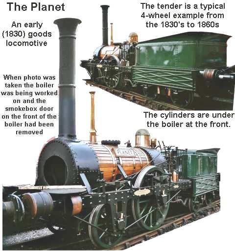
The early loco's based on the successful 'Rocket' built by
Stephenson for the Liverpool & Manchester Railway, served for all services
both goods and passenger. Rocket and other early locomotives on these railways had
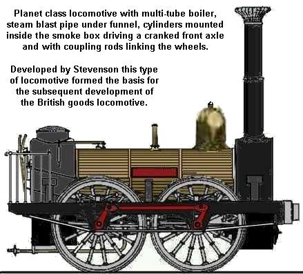
two large diameter driving wheels and two smaller un-powered trailing or leading wheels (0-2-2 or 2-2-0 in Whyte notation) and a small truck or 'tender' to carry supplies of coal and water. The example in the photographs below is Planet and actually hauled the very first goods train on the Liverpool to Manchester line in late 1830. This 2-2-0 was one of the first engines to have the cylinders mounted underneath the smokebox at the front of the engine between the frames and driving a cranked axle. This is called an 'inside cylinder' design and proved a very popular arrangement for British engines. Planet is now preserved at Manchester Science Museum (well worth a visit).
Fig___ The Planet 2-2-0 freight locomotive
Within
a year however locomotives
with bar frames and four driving wheels were in use, only one pair of wheels were connected to the cylinders, the second pair being driven by iron 'coupling rods'. Within the first couple of years on the L&M line differentiation
began to appear with specialised freight and passenger types. The freight engines featured smaller driving wheels to offer more power at slow speeds. Early examples had four wheels
typically four foot in diameter, one pair of these were driven by the cylinders
and the second pair were 'coupled' to the driven wheels by iron rods. In Whyte notation this is an 0-4-0 arrangement, some countries work on axles, in
which case this would be an 0-2-0. The sketch below shows one such early engine, built for the Liverpool and Manchester line in about 1831 it represents a typical freight engine on the time. The boiler is clad in strips of wood to act as insulation. The locomotive had a tender, omitted from this sketch as over the years it operated with a selection of tenders, all I believe four wheeled and similar to that shown in the photo above.
Fig___ Early 0-4-0 freight locomotive
One small point to note is that the driving wheels are mounted inside the chassis side members, this is known and an 'outside frame' arrangement. This was popular on early locomotives, both passenger and goods, up to about 1900 and is still occasionally seen today (notably in the 08 class diesel shunters). The coupling rods for the wheels had to be mounted outside the frames so the axles passed through the frame to an externally mounted crank.
Later two smaller un-powered wheels
were added at the front giving a 2-4-0 arrangement allowing longer boilers, some engines added the small wheels to the rear to produce an 0-4-2, both these types remained popular for small engines working branch lines and quite a number of these small engines survived into the early British Railways era.
The 2-4-0 in turn developed into the 0-6-0 arrangement, which became the standard
for British goods loco's for about a hundred years.
Early British passenger loco's soon
settled on a 2-2-2 arrangement with outside cylinders driving a pair of large
wheels in the centre and smaller un-powered wheels front and rear. On main line express engines the driving wheels could be very large indeed, the 'Stirling singles' used by the Caledonian Railway had driving wheels eight feet in diameter. This gave a
good turn of speed but limited hauling power. A British engineer called
Crompton came up with a design which had four un-powered wheels at the front
with the large driving wheels at the rear. This offered some technical
advantages and the 'Crompton' 4-2-0's were popular on the Continent but were
rare in Britain.
Fig___ Typical engines of the 1860s
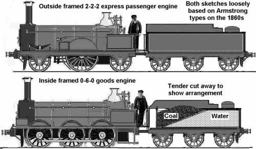
Note how both engines had open cabs at this time, the cab (initially just the front part) was added from about the 1880s. Also worth noting is the rectangular box mounted in front of the single large driving wheel of the passenger engine and in front of the front wheel of the goods locomotive. These held a supply of dried sand which could be squirted down pipes onto the rails using a blast of steam. The sand was used when the rails were wet or oily and the wheels were not achieving traction on the smooth steel surface.
On very
early designs as shown above all the wheels were mounted on the chassis, so the longer locomotives could not manage tight curves in the track and this in turn restricted the size of the boiler that could be used. The Americans
developed trucks or 'bogies' to carry the un-powered wheels into tight curves
and the bogie or 'truck' mounted un-powered wheels soon became the norm
world-wide other than on a few very small engines. These unpowered wheels, usually smaller than the driving wheels, spread the load of the locomotive and also serve to guide the chassis into curves.
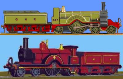
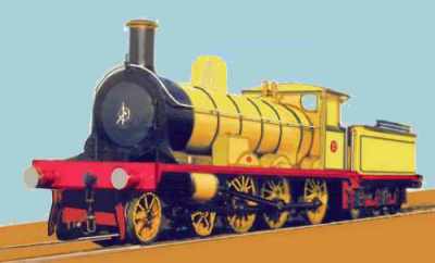
The pistons on a steam locomotive could only operate up to a certain speed, high speed passenger loco's therefore used large diameter driving wheels. In the later ninteenth century a single large diameter driving wheel was common on express passenger engines, originally these were commonly of 2-2-2 wheel arrangements. By the end of the century, with the introduction of the 'pony truck' or 'bogie' 4-2-2 engines became more common on passenger duties (with the rigid chassis 4-2-0 Cromptons favoured on the Continent). The examples shown below are a Stirling Single of the GNR and one of Mr Johnsons Class 115 4-2-2 locomotives, built for the Midland Railway and known as spinners (possibly due to the propensity of the driving wheels to slip when starting).
Fig___ 4-2-2 Express Passenger Engines
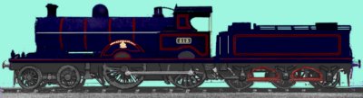
By the early twentieth century a lot of companies were building or buying large (for the time) 4-4-0 and 4-4-2 'Atlantic' engines, which found favour on passenger work. The sketch below is based on a tracing of a photo of the successful LNWR Precursor class of engines introduced in 1904 (130 were built, the last was withdrawn in 1949). The LNWR engines were painted a distinctive 'Plum' with red lining (plum being a rich black with a hint of blue).
Fig___ LNWR Precursor class 4-4-0 locomotive
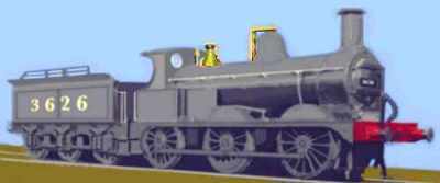
Goods engines had smaller wheels delivering higher tractive effort at slower speeds. The classic goods engine was the 0-6-0 type, of which many thousands were built. The example shown below is typical of the type.
Fig___ MR Johnson 0-6-0 goods locomotive
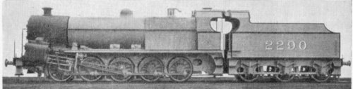
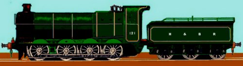
As loads increased so did the tractive power of goods engines, by the 1890s 0-8-0 goods engines were in use, to my eye these seem to be lengthened versions of contemporary 0-6-0 designs. Both inside cylinder and outside cylinder 0-8-0 engine were built. The sketch below shows one of the rather handsome Hull & Barnsley Railway locomotives, this company had a number of 0-8-0 engines from several makers. The H&BR goods engine livery prior to World War One was a very dark green, described as almost black, with blue, yellow and crimson lining.
Fig___ H&BR 0-8-0 goods loco in the early 1900s
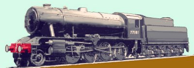
In practice a lot of goods traffic consisted of fairly low density materials (even coal is not that heavy) so the limit on train size and hence required hauling power was often the capacity of run round loops and sidings, limiting the need for really big engines. However by the time of the First World War a heavy goods engine would often be a 2-8-0 (for example the GWR had its 28xx class 2-8-0's and the Great Central had a fleet of Class 8K 2-8-0's). During the war the Railway Operating Department (ROD) had a number of 2-8-0 engines built, based I believe on the GCR engines. During the second world war the Government needed similar locomotives and Mr R. A Riddles (later to become the first CME of British Railways) helped design a suitably basic 2-8-0 machine which became the WD 2-8-0. By the time of nationalisation there were still over seven hundred of the WD 2-8-0's in service along with a small number of WD 2-10-0 loco's. The 2-8-0s proved capable engines, several surviving into BR ownership where they were used for exceptionally heavy loads. Some idea of the power of these 'WD' engines is illustrated by the fact that they were considered over powered for the 1000 ton ICI limestone hopper trains (compared to the thirty tons or so hauled by Planet on its first Liverpool to Manchester run in 1830).
Fig___ WD 2-8-0 goods locomotive
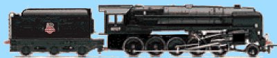
The most powerful goods steam engines built in Britain were the LMS and LNER articulated 'Garrat' types (discussed below) and the BR standard 2-10-0. The BR 2-10-0, classed as 9F, proved a reliable and effective engine however it had a relatively short life in service as it was closely followed by the shift to diesel power. The last BR steam engine built was the 9F 'Evening Star'.
Fig___ BR 9F goods locomotive
Mixed Traffic Engines
By the 1900s a third category of locomotive had appeared, called 'mixed traffic', these were useful engines and could be used on freight or local passenger duties. Mixed traffic engines had driving wheel sizes falling somewhere between the standard goods and passenger engines and were regularly used for cattle and milk trains.
The classic British mixed traffic engine was the 4-6-0 locomotive and the very first of these was the Jones design for the Highland Railway, introduced in the mid 1890s. The sketch below is based on the lone survivor of the class, now preserved in Scotland.
Fig___ 1894 Highland Railway 4-6-0 locomotive
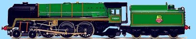
The mixed traffic concept was adopted for the BR standard steam engines, all their tank and tender engines up to the 7MT Britannia class 4-6-2 pacifics were classed as mixed traffic engines. BR did build a single 8P 4-6-2 express passenger locomotive (the only three cylinder type they produced) named Duke of Gloucester. The Britannia was an icon in its day, a rather elegant locomotive which hauled everything from express passenger turns to long coal trains. The design of the Britannia was in many ways similar to the heavy 9F freight engines, in fact the Hornby Minitrix 9F model was their Britannia body mounted on a (Continental) Trix chassis (not exactly accurate but well liked as a model).
Fig___ BR 7MT 'Britannia' class 4-6-2 locomotive
Tank Engines
All the early loco's pulled (or occasionally pushed) a small wagon called a
'tender' behind carrying supplies of coal and a water tank. The directors of
the early railway companies, and subsequently the authorities, decided that
these loco's should not travel backwards as coal dust blowing off the tender
would make it difficult for the crew to keep a proper look-out. This meant
having a turn-table at the end of every line which was expensive to build.
To address this problem the 'tank' engine was developed by engine builders in
Manchester. These have the water tanks mounted on the main chassis and a supply
of coal in a small bunker built onto the rear of the cab. With careful design
of the coal bunker, or with the addition of a rear to the cab, the loco could
travel safely in either direction, eliminating the need for a turn-table. The
first tank engine services were passenger workings on the branch line from
Cheadle Hulme to Macclesfield, south of Manchester.
Tank engines can also
be built with very short wheelbases, making them a natural choice for docks and
other industrial uses where curves tend to be tight.
Tank engines come in
four basic types, depending on where the tank is mounted. Most common was the
'side tank' arrangement, where the tanks were mounted on the chassis to either
side of the boiler. Saddle tanks have the water tank wrapped across the top of the boiler,
a design that proved popular with industrial users. The 'pannier tank' was favoured by the GWR, on these the
tanks are hung on the sides of the boiler, not actually supported on the
chassis. They were actually a modified form of saddle tank necessitated by the design of boiler being used on the engines in question. The 'well tank' has the
water tank slung under the boiler, as this space was limited there were often supplementary tanks, typically in the form of two rectangular small tanks, one either side just ahead of the cab. The well tank was never terribly common in Britain (it was more popular on the Continent) although a few were built for the pre-grouping railways in the South. Well tanks are not something I know a great deal about so I asked on the uk.rec.models.rail newsgroup and Andrew Breen was kind enough to supply some additional information -
Well tanks weren't uncommon at one time, and neither were their
sister-type, back-tanks.
In a well tank the tank was between the frames, under the boiler and
almost invariably wholly ahead of the firebox - this restricted the type
to outside-cylinder engines in most cases (in broad-gauge engines
a well tank could be fitted between inside cylinders and cranks).
In a back-tank the tank was between the frames but behind the firebox
- this was a common arrangement for inside-cylinder engines in the mid
to late 19th century.
Tank engines are usually distinguished by adding letters to the end of the numbers describing
the wheel arrangement. The side-tank being the most common just had the letter
T added, for example the Graham Farish 'Jinty' loco would be described as an
0-6-0T. Pannier types such as the Graham Farish 57xx and 96xx tanks were
suffixed PT as in 0-6-0PT and the Graham Farish Austerity saddle tank would be
described as an 0-6-0ST. The pannier design was derived from the saddle tank and adopted by the GWR to allow the use of the Belgian designed Belpaire firebox The 'well tank' was sufficiently rare that the WT
suffix is seldom seen. The Beattie LSWR well tank shown in the sketch below (NOT a scale drawing by any means) was the only one to find favour. Built for short suburban passenger runs it was found to be too small and with a requirement for frequent re-watering, however a few survived on one line (the Wadebridge and Bodmin Railway) where their low weight was an advantage on the lightly built track. They were built by Beyer-Peacock of Manchester in the later 19th century and (with several re-builds and modifications) lasted into the early British Railways era. The basic types of tank engine are shown below, note also the introduction and evolution of the driving cabs on succeeding generations.
Fig___ Tank engine types
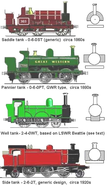
The asymmetric arrangement of wheels (as shown on the saddle tank locomotive in the sketch above) was fairly common in the early years but seldom seen after about the 1890s. As the wheels are sprung on six (or more) coupled engines you cannot use a single bar connecting all the driving wheels so the coupling rods are in sections (as shown on the pannier tank engine above). Tank engines were widely used on branch lines and for suburban passenger services as they did not need the use of a turntable at each end of their run, their limited fuel and water capacity made them less suited to long haul routes. Steam engines were basically reliable and tank
engines built in the 19th century lasted in railway service into the 1960s and a few lasted into the 1980's in
industrial locations such as collieries, quarries and docks.
Compound engines
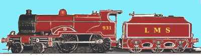
The compound engine uses the steam more than once, from the boiler it passes to a high pressure cylinder where it drives the wheel for half a revolution, on the exhaust stroke the steam passes to a low pressure cylinder, extracting more energy from it and making the whole system more efficient. On marine steam engines the 'triple expansion' engine was common, using the steam three times in ever decreasing pressures before allowing it to escape. On railway engines double expansion was the norm, although only employed on more powerful engine types. Typically the standard high pressure cylinders were mounted on the outside of the engine in plain view, the exhaust being fed to a third low pressure cylinder mounted under the engine out of sight. The Midland Compound 4-4-0 is a well known example of this arrangement, it has two cylinders mounted on the outside driving the wheels with a third low pressure cylinder mounted underneath the engine out of sight and driving a cranked axle. On a two cylinder engine there are four 'puffs' per revolution of the wheels, the three cylinder arrangement gives a distinctive and slightly 'off-beat' sound.
Fig___ Midland Railway Compound Engine
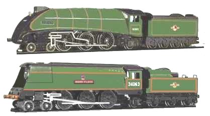
Streamlining and air-smoothing
In the 1930s aircraft captured the public imagination and the 'streamlining' developed for aeroplanes came to represent the 'modern'. The railway companies took some note of this, the potential for reducing drag and hence fuel consumption was an attractive idea but more importantly the public would see a streamlined locomotive as inherently better than the 'old' style engines. In practice streamlining made little difference to locomotive performance and made maintenance more difficult so few streamlined locomotives were built. The LNER lead the way with their fleet of A4 4-6-2 engines, one of which, the Mallard, still holds the world speed record for a steam engine. This had a smoothly curved front end with sheet metal cladding covering the boiler itself and originally sheet metal covers over the wheels as well. Maintenance problems soon saw the wheel covers removed but the type remained in service well into the British Railways era. The LMS also introduced a streamlined 4-6-2, known as the Coronation Scot, broadly similar in shape to the A4 but featuring a distinctive all-over maroon livery with white 'go-faster' stripes on the sides. These LNER and LMS types were the front runners in the ongoing and officially unofficial annual race to Scotland. The GWR had a half hearted attempt at the job, taking a single engine and adding a bulbous nose to the firebox and some air-smoothed casing to projections on the boiler but this was soon removed. The SR built a distinctive class of engine they referred to as 'air smoothed'. The Merchant Navy class 4-6-2 engines had a rectangular sheet metal box added around the sides of the engine, although the front retained the conventional firebox door. Again this was found to offer little advantage and in later years the casing was removed, the locos then being known as 'rebuilt Merchant Navy' engines.
Fig___ Streamlined Engines
Double and articulated engines
On steam locomotives the pistons powered
only one wheel on each side directly, the rest of the driving wheels were driven or
'coupled' by the connecting rods. It is common practice to describe both an 0-4-0 or a 4-4-0 as a 'four coupled' locomotive. Broadly speaking the more coupled wheels the greater the tractive effort, that is the bigger the load that can be pulled. There is a further possible variation, that is whether the
wheels are connected together by 'connecting rods' on the outside or by
gearing, usually on the inside.
Gearing is more difficult to manufacture, however it has some uses. In the USA they needed a powerful engine that could manage very tight curves in logging camps, their solution was the Shay engine, having a drive shaft run along the chassis with the power supplied via gears to four wheeled swiveling bogies, one under each end.
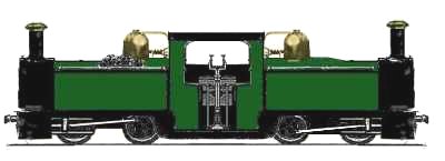
A British engineer by the name of Fairlie who, in the 1960s, came up with a variation on this idea. Fairlie felt there should be no un-powered wheels on a locomotive as this wasted the adhesion from the weight of the engine. The Fairlie engine has the boiler and cab mounted on a rigid chassis supported by two sub-chassis, each of which is equipped with pistons and wheels. The sub chassis were free to swivel in the manner of bogies, in fact this design can arguably be said to be the origin of the bogie, allowing tight curves to be negotiated but retaining the simplicity of the basic steam engine design. The idea found favour mainly with narrow gauge lines and the Ffestiniog Railway was an early adopter (they still use the type having had several over the years). The Whyte notation for these locomotives is 0-4+4-0. The plus sign indicating that the wheels were on a separate sub chassis.
Fig___ Fairlie Loco
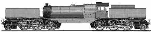
A later development of this idea was developed by a man called Garrat, a British engineer working in Austrailia, this has a single large boiler but carried on two bogies. The Garrat design was developed for use on narrow gauge lines but also used on some large main line locomotives, essentially offering the power of two engines but with only a single crew. These large articulated engines, saw service in areas of the world where very heavy loads needed to be handled over steep gradients. In Britain standard gauge garrat type engines were used for a time by both the LNER and the LMS in the form of a 2-6+6-2 locomotive to haul iron ore trains and the like.
Fig___ Standard gauge Garrat loco (generic sketch)
On most larger diesel and electric loco's the
driving axles are powered individually and with two exceptions (the Fell locomotive and the GT3 gas turbine engine, both discussed in the section on diesel engine types) only diesel
shunting locomotives have the heavy steel connecting rods on the sides in
Britain.
Fireless and Condensing Locos
Two oddities were the 'Fire-less' and 'condensing' locomotives, developed to meet the needs of specific duties. Fireless loco's are charged with high pressure steam
from a central boiler plant, they can run for quite some time between charges. The sketch below is a generic 'fireless' loco based on no particular prototype but typical of the type. The 'fireless' engine was used in industrial locations where sparks might be a problem (paper works, chemical plants and the like). Although they may look antiquated one at least remained in service well into the 1980s at a British Glaxo works.
The 'condensing' locomotive was developed for use where long runs through tunnels were frequent, such as in central London. These were required by law to 'consume their own smoke', for fairly obvious reasons. To achieve this the exhaust steam was routed through thick pipes running back from the smokebox to the side mounted water tanks which were used to condense the steam, reducing the emissions. The Great Northern Railway class N2 was a good example of the type, familiar to many as it has featured in the Hornby range since the days of tinplate track with three-rail pickup.
Fig___ Fireless and Condensing Locos (generic sketch)
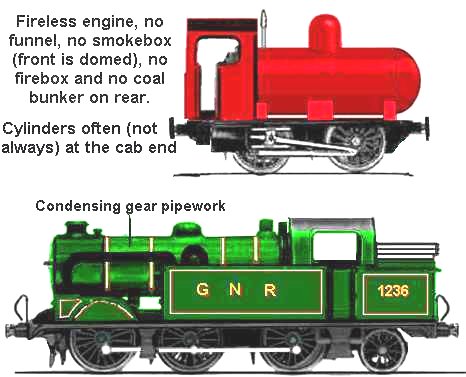
As electric traction was introduced in London the condensing tanks were reallocated elsewhere and (I believe) most then had the condensing gear removed.
Final developments in British steam traction.
Locomotive
development continued with each of the railway companies and locomotive
builders (of which there were over two hundred in the UK alone) producing new
loco types every few years and by the time of Nationalisation there were over
four hundred different types of steam loco operating on the British railway
system.
Pure passenger loco's were mainly the
express such as the GWR Castles and LNER streamlined Pacific's, but also
included smaller types such as the Midland Railway's 4-4-0 tender loco's. The
Graham Farish 4-4-0 'Midland Compound' loco's were built at the turn of the
century and phased out on British Railways in the 1950's having spent all their
working life hauling passenger coaches. Generally the only goods trains hauled
by express loco's would be high value perishables such as milk or fish behind
larger classes on longer hauls. The Southern Railway used large Maunsel S15
class 4-6-0 tender loco's for hauling the heavy freights out of Southampton
docks.
Mixed traffic loco's, which could be used for passenger or light
goods work, ranged from quite large types such as the GWR 'Hall' class and the
LMS Black 5's, both 4-6-0 designs, through various tank types, mainly 2-6-2's
and 2-6-4's down to small 0-6-0 tank engines. BR designated all its standard tank engine designs, and tender engines up to the 7MT Britannia class, as 'Mixed Traffic'
The 0-6-0 loco was the
standard British goods and small mixed traffic type, outnumbering all the
others put together. First developed in the middle of the 19th century examples
of early types remained in service into the 1950's. Pure goods loco's included
many tank engines, although tank engines were also used on suburban and
branch line passenger work. For longer hauls there were tendered loco types
such as the SR's Q1 0-6-0 and the GWR 'Dean Goods' 0-6-0 loco's. For heavy
freight trains larger loco's were used, such as the LMS Fowler 2-8-0's that were
first built in the 1920's and lasted into the 1960's. There is one further type
of locomotive, the 'shunting' loco, used for moving rolling stock from place to
place within stations and goods yards. Passenger stations might have a single
small tank engine for this work, usually called the 'station pilot',
marshalling yards and larger goods yards also required shunting locomotives and
in Britain these were usually small tank engines usually 0-4-0 or 0-6-0 types.
When diesel powered engines were built the shunting locomotives retained the
0-4-0 and 0-6-0 wheel arrangement.
By the late 1940's diesel power was
already established in the USA and was rapidly being developed in Europe but
British Railways were born in a time of necessity so they decided to stay with
the steam engine.
Supplies of good quality coal were in short supply and
skilled men were lost to other, less dirty, post-war industries. The BR
'standard' loco's were therefore designed for low maintenance and poor quality
coal. All the BR standard designs were used as mixed traffic types and could be
seen on all sorts of duties. BR did differentiate by livery, lined green for
main line passenger loco's, lined black for mixed traffic types and plain black
for pure goods loco's.
For descriptions of the BR standard steam engines see the separate section Steam Locomotive Types in this appendix.
The BR standard steam locomotives were to have a short
working life, the 1955 Modernisation Plan emphasised the move to diesel power
and financial pressures added momentum to this move. A steam engine spent
typically 5 to 10% of its working life parked somewhere being maintained,
diesels were seen as a more efficient and less labour intensive alternative
(labour was a problem at the time, hence the large scale assisted immigration
program sponsored by the Government).
Steam disappeared first on Western Region in
1965, the last BR steam trains operated on London Midland Region in the North
West of England in 1968. London Transport and industrial users continued
to use steam after this time however, with some interesting `fire-less' types
operating in hazardous environments such as paper mills where fires were
generally undesirable. Steam was used on the LT and private industrial lines (notably collieries and steel works) well into the 1970's.
The switch to diesel locomotives
Petrol and later diesel engined locomotives with simple mechanical transmission had been in use on railways since the early twentieth century. During the First World War a number of these engines were built for use on the 60cm gauge trench railways. The mainstay of these little lines were small tank engines but the exhaust from these invited artillery attack so the petrol engines were used for the last leg of the run up to the front line. The petrol engines were light weight so could not haul heavy trains but they proved adequate for the work. After the war the war surplus narrow gauge engines, both steam and petrol, were sold off and used in quarries, mines and other industrial systems.
The 40hp petrol engined Simplex design proved popular and standard gauge examples entered service in the post war era for shunting and light railway use. Several were purchased by the railways, the earliest I have seen reference to was purchased by the L & Y but the NER, GER and GWR all had at least one of these engines. Standard gauge Simplex engines also saw service with industrial users, often being fitted with over size buffers to prevent 'buffer locking' on the tight curves of industrial lines. The Simplex 40 hp standard gauge engine below was used to haul wagons from the railway proper along a privately owned tramway line to a paper mill in Kendal (I think it remained in service into the 1950s, possibly the 1960s). The photo from which the sketch was made shows the loco hauling two twenty ton coal hoppers an ex LNWR van and an LMS container on its flat wagon.
The pre-nationalisation companies were well aware of the poor energy efficiency of the steam engine and various experiments were already well in hand by the time of nationalisation, the LMS and SR had a couple of large diesel electric loco's on order and the GWR had a single
gas-turbine loco on trials. It should be noted however that in the first half of the twentieth century the various internal combustion experiments were undoubtedly significant from a technological viewpoint but most of the UK railway system would never have seen one of these machines. There were perhaps a hundred or so internal combustion engined railway vehicles built to fifty or so designs but these numbers were dwarfed by the thousands of steam locomotives built to a thousand or so designs produced in the same period.
The limitations of the direct mechanical drive meant that petrol and later diesel engines were only used on comparatively light duties such as lightweight passenger railcars (such as the thirty odd diesel powered units operated by the GWR) and small shunting engines. The GWR railcars used direct mechanical transmission via a simple mechanical 'crash' gearbox, this had no synchromesh, the driver had to match the engine speed by ear to the desired gear, this was the norm on road vehicles until well after the second world war. Slow running was also a problem for internal combustion power, the LNER built one steam and diesel engine which had steam supplied to one side of the cylinder with the other being run as a diesel engine. The steam was used to start the thing moving and to get the thing up to a sensible speed then the diesel side was cut in for the run. This did produce a significant fuel saving, but the engine still required a steam boiler so the savings were not good enough to justify further experiments.
One early solution was to use electric motors supplied from an on-board generator, this offers several advantages and the NER operated a petrol-electric passenger units as early as 1903 (see Appendix Three - Diesel Electric Multiple Units for details and an illustration). In the 1920s the LMS converted a couple of old two-car L & Y electric multiple units into a single four-car unit with a diesel powered generator and a number of small shunting engines were built using diesel-electric propulsion (culminating in the iconic BR Class 08)
Diesel developments elsewhere had been
studied; the Americans favoured a diesel engine driving an electrical generator
with electric motors driving the wheels whereas the Germans had developed a
system where the diesel engine powered a hydraulic pump and hydraulic motors
powered the wheels.
For larger locomotives the electric transmission system was considered attractive as it was felt
that British industry could readily adapt its expertise, but on the Western
Region the high power to weight ratio of the successful German designs were better suited to the lightly constructed branch lines.
In the event the diesel-hydraulic loco's built for WR were more successful than
some, less successful that other diesel electric designs. The drive to standardise and rationalise the diesel fleet saw the diesel hydraulic fleet withdrawn (although the engines had many years of useful life left in them at the time) and the diesel-electric loco became the standard on British lines.
Only one
diesel-mechanical direct-drive main line loco was tried in the UK, this was the Fell
Development Ltd number 10100. I. G. Ivatt of the LMS was involved in this
project, and the loco performed well on passenger duties on the London Midland
Region between 1952 and 1958, but in the event only a single prototype was
built. It was destroyed in 1958 by a fire which started in the loco's steam
heating boiler (see also the separate section on Diesel Locomotives in this appendix for a sketch and further information on this unusual prototype). The trials of gas turbine engines for railway use had started off well enough, and the essential simplicity and low maintenance required by these engines was attractive but these engines are not fuel efficient and following the oil crisis of the 1970s interest evaporated.
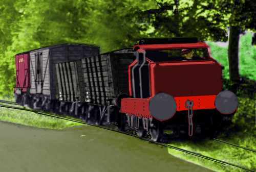
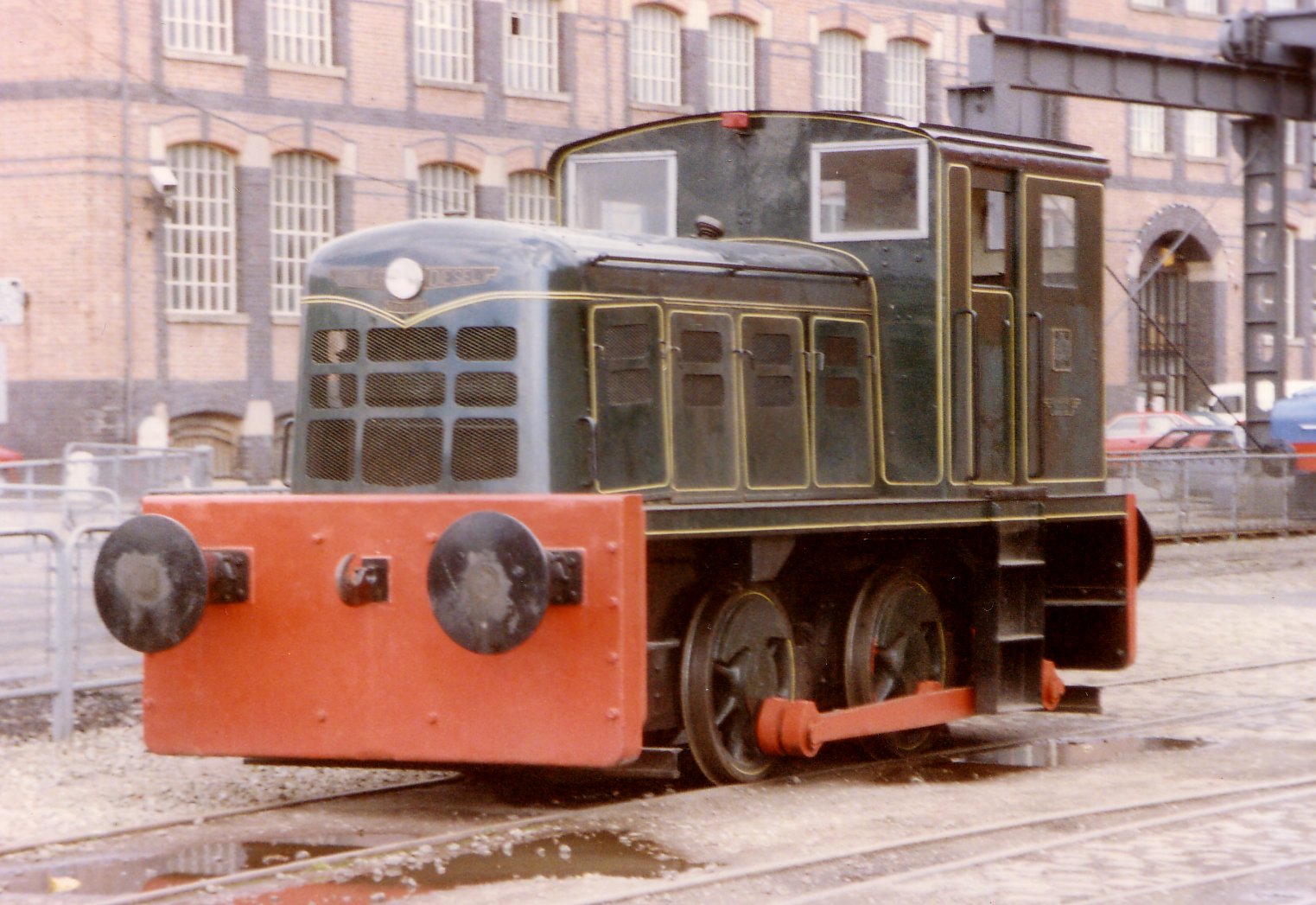
The example below is a small 0-4-0 diesel shunting engine, it was used on an industrial line and was photographed at the Manchester Museum of Science and Industry in the mid 1980s. Small engines of this type, which includes a jack-shaft drive, are a difficult proposition in N (although I understand that bachman Farish are to introduce a BR class 02 engine of similar proportions).
In the 1950s the motor manufacturer Leyland needed a transmission system for their heavy 'Hippo' lorry and they came up with the fluid coupling. This proved suitable for use on diesel multiple units and was widely used on the new DMUs introduced in the 1950s, although for the heavier units built for long haul express duties the diesel-electric system was used.
Diesel classification, numbering and headcodes
As with the steam engines diesels are distinguished by
their wheel arrangement, un-powered axles are indicated by a number, groups of
powered axles by a letter, A for one axle, B for two etc. British locomotives
were either diesel-electric or diesel-hydraulic, on both of which each powered
axle usually has its own electric or hydraulic motor. Loco bogies with four
powered wheels are called B, bogies with six powered wheels are called C. If
the wheels are not mechanically coupled a small letter o is added hence the
Class 20 is a Bo-Bo loco and the class 37 is a Co-Co loco.
One oddity
was the Fell diesel-mechanical loco mentioned above. This had a four
wheeled un-powered bogie at each end and a set of four powered axles in the
middle, mounted on the chassis and connected together by coupling rods. In
steam notation that would be a 4-8-4, in diesel notation it is a 2-D-2.
On
some loco's there is a mix of driven and un-driven wheels on each bogie, for
example the A1A A1A loco built by Brush, on which the outer axles on each six
wheeled bogie were driven but the middle axles were not. The Class 40 is a
1Co-Co1, which means it has a single un-powered axle on the front of the bogie,
followed by three powered axles, not connected by coupling rods or gears, then
a second bogie with another six powered wheels and a single two-wheeled
un-powered axle on the end.
BR diesel loco's were originally numbered
in the same way as steam loco's, with a five figure number but this soon changed
to a three or four digit number prefixed by the letter D. In 1968 this changed
again with the introduction of numbers based on the power of the loco, small
loco's such as shunters were type 0, loco's of about the 1,000 horsepower range
were type 1, those in the 1,000 to 1,500 hp range were type 2, 1,500 to 2000 hp
was type 3 and those with about 2,000 horsepower were type 4. With the
introduction of the Deltics a new class of Type 5 was started. There were
several cases where the D prefix was incorrectly added to the new number. In
1973 the entire numbering system was overhauled to suit the new TOPS traffic control system and the now familiar 'Class'
numbering system was introduced.
The Class 20 type loco, available
from Graham Farish, was one of the first diesel-electric loco designs to appear
but the poor visibility over the long engine was considered to be a problem. A
different design of loco with a centre mounted cab and lower bonnets was
ordered instead (the Class 17 'Clayton') but this proved unreliable and eventually more of the Class 20
type loco's were ordered. At the end of the 1960's there was a major sorting out
of loco stocks, with smaller classes and unsuccessful types all being withdrawn
along with all the Western Region diesel hydraulic fleet.
Early diesel loco's had a set of discs mounted on each end, these discs
could be folded in half, presenting a plain semi-circle the same colour
as the body, or opened out to show a white circle. These mimicked the lamps
used on steam loco's to indicate what kind of train they were pulling. This was
changed, starting in 1960, to a system using a four character (letters or
numbers) 'head-code' as described in the chapter on Communications Signalling
and Control under Bell Codes & Locomotive Head Codes. These were commonly arranged in two pairs to either side of a set
of doors built into the ends of the loco's, these doors were to allow staff to
move between loco's on the move. This idea was not a success, the doors made the
cabs draughty and staff seldom used them so the doors were removed, at which
time the head-code panel was usually moved to the centre of the loco front.
Some loco's had the head-code panel mounted at the front of the roof, above the
cab, an example is the Minitrix Class 27.
Steam heating and additional brake power on diesel engines
The demise of the steam loco
gave rise to some problems; steam had been used for heating both on passenger
stock, including the British Railways Mk.1 coaches, and for banana and some
fruit vans. The new plan called for electric train heating (usually abbreviated
to ETH). During the transition some diesel loco's were built with steam heating
boilers, this is relevant in that a rake of Mk.1 rolling stock double headed by
a Class 33 and a Class 25 would probably have the 33 (ETH only) leading, with
the 25 providing the steam for heating. Some coaches were built, mainly in the
Western Region, with dual heating, both steam and electric, and these were
loaned out to other regions on occasion. There were also 'train heating boiler
vans', usually converted from the longer wheelbase goods vans and horse boxes.
Only a few were built, for use in Southern and Western Regions, where they
stayed mainly in the South West and were used among other things for heating boat-train
coaches. They were (I believe) painted in passenger colours but as there was a
prohibition on non-bogie rolling stock travelling in main line passenger trains after 1959
I would doubt they were used for normal passenger duties. These boiler vans lasted
at least into the late 1970's, presumably for pre-heating coaches, and might have
been useful for steam-heated banana vans and the like.
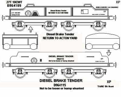
As the diesel loco's were lighter than their
steam counterparts, and as the majority of existing stock was still not fitted
with an automatic brake, special 'brake trailers' or 'brake tenders' were produced. These were
simple vehicles running on passenger bogies equipped with vacuum brakes and
loaded with scrap metal as ballast. Early versions had a rather square box
shape, later versions were fitted with a streamlined casing. These were
attached to the loco on un-fitted goods trains to improve it's braking power,
in the early days they were usually pushed by the loco but in the later 1960's
they were placed between the loco and the wagons. There were times, with
particularly heavy trains, where they used two tenders, one running in front of
the loco, the other behind. A whitemetal kit of a brake tender, which runs on
two Graham Farish passenger bogies, is available from P.D. Marsh.
Fig
___ Brake Tenders
The drive toward standardisation and rationalisation of the diesel fleet was not without its problems. Part of the modernisation plan called for the use of large 'hump'
marshalling yards where the yard shunting engines were required to push the wagons up the hump. The standard BR 350hp '08' class diesel shunters proved under-powered for this
work and a special variant, TOPS class '13' was produced for use at the big
Tinsley yard. The Class 13 consists of a standard '08' with a second cab-less
08 unit permanently coupled to it. Shunting loco's are not designed for speed,
diesel-electric shunting engines built by BR were often damaged when the driver
allowed the speed to creep up and the electrical armatures in the motors came
apart under centrifugal force. In the 1980's however Southern Region re-geared some
'08' class loco's to allow higher speeds for use of short haul 'trip' goods
duties and since then more 08s have been similarly modified, although I am not sure what duties these perform.
For more on the development of diesel engines see the separate section Diesel Locomotive Types in this appendix.
Electric Locomotives and Services
Electric trains have been operating in the UK since the late nineteenth century and the electric motor lends itself well to powering a train. The 'diesel' locomotives, with few exceptions, have all used their engine to drive a generator to power electric motors. Electric power allows for rapid acceleration and is well suited to stopping suburban services, it is also preferable for 'underground' lines or lines with steep gradients in long tunnels, where steam engines in particular made life rather unpleasant.
The first electric trains on the London Underground railway system appeared on the City & South London Railway of 1890 and the inner London underground system was fully electrified by 1905. In the early years a separate electric loco was used, hauling passenger coaches built to suite the tight clearances of these lines, but fairly early on the self contained multiple unit appeared and soon dominated passenger services.
A study by BR found that electric traction, even on main lines, worked out cheaper per ton mile than steam and diesel power, although a substantial investment in infrastructure is required. 'Regenerative braking' in which the motors are switched to act as generators pumping power back into the supply adds to the efficiency (a saving of 20 percent on generating power can be seen in suburban services with regenerative braking). Regenerative braking is often referred to as a 'new technology' but the idea has been used on various electric locomotives since about the time of the First World War.
To supply electrical power to the engine two approaches have been used, one was to suspend a wire above the tracks and use a horizontal pick-up bar to collect current, the other was to supply the power on a third rail mounted between or, more commonly, beside the track. The current requires a return path to complete the circuit, this can be the running rails (this is standard practice on overhead supply and surface third rail services) or a separate rail mounted on insulators (this approach is used on 'underground' lines in damp tunnels where earth leakage is a problem). Using the running rails, especially for DC supplies, leads to problems with electro chemical decomposition causing damage to the rails themselves but with decent bonding to ensure the most appropriate 'return path' is taken this can be minimised.
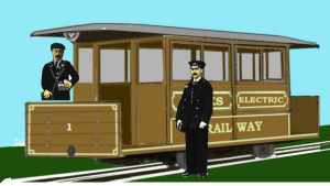
Magnus Volk (an electrical engineer working for Brighton Corporation) tried a two-rail electrification system for his narrow gauge line in Brighton in 1893 but ran into problems with leakage between the rails (the line subsequently switched to using a third rail mounted on insulators to supply current and a wider gauge, it remains in use today). The sketch below shows the first unit built for the line after the gauge was widened. The driver operates the controls standing at the front of the veranda (just about where the conductor is shown on the sketch). The round grey object at the bottom of the front is a buffer, the units could operate with a trailer coach at busy periods.
The Lancashire & Yorkshire electrified the main line between Liverpool and Southport in 1904 using a third rail to supply 630v DC to the trains. The Liverpool Overhead Railway and the LNWR North London suburban services opted for a fourth rail supply as used on the underground system but three rail systems were the norm for surface lines.
The big problem with a three or four rail system comes in yards where men had to work stepping over the live rail, several companies with three rail systems employed an overhead wire in their yards and equipped some locomotives with both a rail pick-up shoe and an overhead pickup, an early example being the North Eastern Railway Bo-Bo engines used on the Tyne Dock line. This practice of fitting both kinds of pick up has continued into the present day in the London area (examples of dual pick up locomotives can be found in the section on Electric Locomotives). As speeds in yards were slow the overhead wires used on 'third rail' systems were usually of the simple 'tramway' type, a wire suspended across the area with the conductor wire suspended from it. The voltages were comparatively low so clearances could be tight and insulators were small.
At various time there has been consideration given to adding a protective sheath to the current supply rail to protect people and animals and to reduce the problems caused by ice forming on the power rail. This has been studied most recently (I believe) for the planned Kent coast electrification scheme, however the additional complexity and cost has meant this option has not been adopted. For one thing the third rail has to be broken where it reaches points and the like, and guiding the pick-up back into the next section of sheath at speed would represent a fair technical problem. The Lancashire and Yorkshire 1200v DC third rail system had the collector shoe running in a slot, however I believe the outer face of the rail was energised and hence still dangerous. There may be tram systems using a protected third rail but if there are I am not aware of them. There have been various experiments using the two running rails as the supply and return rails however this necessitates low voltage supplies, requires insulated running wheels and there were always problems with current leakage, as far as I know this system is confined to model railways at present.
Another problem with three (or four) rail DC supply is that the low voltage, and corresponding high current, limits the power of the engines that can be used. The highest voltage I know of on such a line was the L & Y Manchester to Bury 1200v DC third rail line (opened in 1916). That was I believe at the upper limit of voltage that can be used and the modern systems all use much lower voltages. This will become an increasing problem as faster trains and in particular air conditioned units are increasingly required. In the North London area there has already been a gradual move toward switching from three rail to 25kV overhead supply and over time this trend may continue. In Holland the standard supply has been 1500v DC overhead wire feed for many years but they are now building all now locomotives to operate on dual 1500v DC and 25kV AC supplies and slowly changing their system over. This will take many years to complete but they evidently feel that the additional power will be worth the effort.
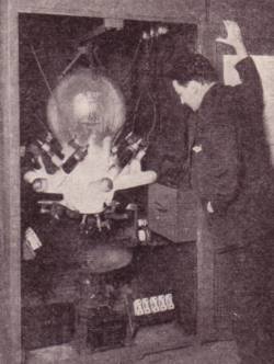
One problem with AC supplies is that the actual motors used are always DC types, hence the supply has to be recified. Up to the 1960s this involved the use of large glass 'mercury arc rectifiers' consisting of a large glass sphere pumped out to a vacuum with a pool of mercury in the base (serving as the cthode) and several anodes mounted near the top of the glass sphere. These were used to convert the AC mains supplies to DC for DC operated railways and were also used on early AC electric locomotives (including some trams). The example shown below is a 400KW type and has a large fan mounted underneath it to keep it cool.
To collect current from an overhead wire some form of pick-up is required. The Manx Electric Railway on the Isle of Man, opened in 1893 and still in use today introduced this system, becoming the first overhead supply electric railway in the world. The pick up consists of a 'trolley pole', essentially a pulley-wheel on the end of a spring-loaded stick (for more information on trams see Appendix One - Set Dressing - Public Service Vehicles). This is really more of an electric tram system than a railway, it runs on 500v dc from the overhead wire. In 1894 Werner Von Siemens demonstrated an electric tram in Berlin which used two wires and a small four wheeled trolley running along the top of the wires to supply power. This was not a great success, and trams generally adopted the Manx type 'trolley pole'.
In practice tram pickups did sometimes disengage (known as 'unwiring' and most often when they hit the frog of a diverging line) but the driver could dismount and hook them back on. Trains are not supposed to stop between signals, the block working system had become mandatory in 1889 but some lines continued using the 'interval' system up to about the time of the First World War (see also Communications, Control and Signalling - Communications & Control Systems) where unscheduled stops between signals could be positively dangerous.
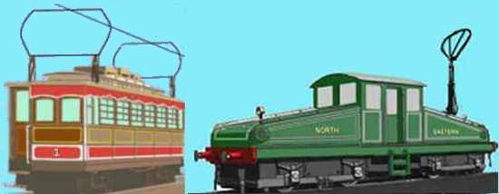
The trolley pole was patented by an American by the name of Sprague, Werver Von Siemens came up with an alternative approach called a 'bow collector' to avoid paying royalties. This consisted of a horizontal bar held up against the wire by a spring mechanism to allow for irregularities in the height of the wire. I am told that the term 'bow collector' refers to the cross section of the pick-up bar having a curved top, all types of bow collector had to be angled back in a trailing direction, so at the terminus the collector was shifted, usually using a rope. The original Siemens design was in the form of a hoop of metal with a flat section at the top for current collection. The hoop was usually as wide as the vehicle on which it was mounted and the shape meant that the overhead wire could not be caught by the collector. This type of pickup was used on some trams (mostly in Europe) but today a working example of the type can be seen on the passenger units of the Isle of Man Snaefell Mountain Railway (shown on the left in the sketch below), the pick up hoops are supported by springs at the base. The original locomotive built for the NER Tyneside line to the docks had a curious hybrid design with a hoop type bow collector mounted atop a mast mounted on the bonnet (shown on the right in the sketch below).
Various methods were used, the sketch below shows a Lancashire & Yorkshire engine built for the Southport line and photographed in about 1909 which (in addition to third rail pick ups at each end of the chassis) had pairs of long trolley-pole booms with a horizontal bar pick-up to supply power in yards. Unlike third rail system (which must have gaps in the conductor rail around pointwork) the overhead pickup should always remain in contact with the wire but to add a further element of safety two pickups were commonly fitted to railway engines right up until the later 1960s. The L & Y engine has a bow collector on each side of the cab as well as the third rail pick-up shoes at each end of the chassis, the photograph I used for the sketch is the official three quarter view and shows both bow collectors raised, with this type of bow collector however I believe only the trailing pick up would be raised in service, on some engines the entire assembly was mounted on a turntable to allow it to be swung round to lie in the trailing direction.
The long booms of the L & Y engine must have caused a few problems on curves, although the LBSC AC electric multiple units of 1909 used a similar style of pick-up (angled back toward the centre of the power coach). This has been sketched in App-3 - Electric Multiple Units - London Suburban Services.
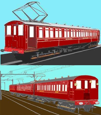
By about 1900 the basic bow collector had evolved into the double-diamond pantograph design, named after an adjustable parallelogram used in making scaled copies of drawings. The NER locomotives soon had one of these fitted to the roof in place of the bow collector (illustrated in Appendix Four - Electric Locomotives). An example of the double diamond pantograph is shown below on the MR electric motor coach.
The cross bar of the pick up on overhead collector systems has a deep droop on the ends so that should the pick up move out of line with the wire the wire could not then get underneath it (which would be dangerous as there would be no way to disconnect the engine and it might pull the wire down). Even modern pantographs have this but in the form of thin metal rods in a U shape on each end, making it less easy to see. On the modern pantograph these drooped ends are called horns', they are designed to break if they hit anything and when they do the (pneumatically operated) pantograph is automatically lowered to avoid further damage.
Overhead supplies can employ higher voltages and are the norm for high voltage AC supplies.
In 1908 the Lancaster-Morecombe-Heysham line, operated by the Midland Railway, was electrified using an overhead wire delivering 6.6 kV, 25 Hz AC supplied from the railway company generating station built to service their Heysham dock complex. This supply was chosen as the MR was operating their own power station (to supply Heysham docks) delivering this voltage but 6.6kV 25Hz was used in several locations in the USA at about the same time and was subsequently adopted by the LBSCR for their London overhead electrification. The eloectrical equipment was supplied by two firms and the two photographs I have found showing these units show different styles of pickup, one has a diamond pantograph type, the other usues bow collectors supported on twin booms. I am not sure if the two types were associated with different manufacturers or if the bow type was subsequently replaced by the diamond type.
Overhead supplies employ a wire suspended above the track to supply the current but wires tend to droop and even with two pickups the droop in the wire was often a problem. I understand the Midland Railway's Lancaster to Heysham line tried metal rail suspended above the track but that did not seem to have been a success. By about 1905 someone had come up with the catenary wire system, in which a supporting cable is allowed to droop in to its natural curve (the name of which is catenary), below this dropper wires carry the actual current delivering cable. The dropper wires can be closely spaced, so there is very little droop in the supply cable and the pantograph remains in good contact even when the train is travelling fast.
By the time of the First World War overhead supplies were in use in several locations, notably in the North East, and various supply voltages both AC and DC were in use around the country. The 1500v DC overhead system had proved very reliable, in use in the North East, North West and North London areas it had been adopted by several countries and was under serious consideration as a British national standard. Meanwhile however the French had been experimenting with 25kV overhead supplies and the British Transport Commission decided this should be investigated.
The former Midland Railway line to Heysham was used for trials of equipment for the new AC standard. The line was re-electrified using 6.6kV at 50Hz (although a number of components used were full size 25kV kit), this line was then used to experiment with the design of wire suspension systems and pantograph pick-ups in order to develop a suitable design for future high speed running.
The engines used for the trials were converted from LNWR four-rail North London stock dating back to just before the First World War. Up to this point the standard pantograph was essentially the same as that on the original Heysham unit shown above, two diamond shapes supporting a cross-bar. This design was found to have problems when running at high speeds. The Heysham trials included a singe-arm or 'arm and elbow' type pantograph from the French company Faiveley (who were involved with the Paris Metro system) and produced the early versions of the British arm-and-elbow single arm pantograph design, variants on which have been in use ever since (see also 'Appendix Three - Electric Multiple Units' for details of the stock used on this line).
The oft quoted '50Hz 25kV standard' was actually a dual-standard as BR built EMUs and locos up to the Class 87 were equipped to run on either the full 25kV or a reduced voltage of 6.25kV. The lower voltage allowed for tighter clearances in tunnels and under bridges and was widely used in the London suburbs, the Glasgow area and other parts of the country. In practice the lower voltage ran into problems with the electrical gear used, in Glasgow and London EMUs encountered problems with transformers burning out (due I believe to switching transients). It was then found that the clearances on the full 25kV supply could be rather tighter than had been thought and the 6,25kV was gradually eliminated from the system. I believe the last 6.25kV line changed over to 25kV in 1983.
The early 25kV electric locomotives used a variety of pantograph types, including a so called cross arm design which looked somewhat similar to the 'double diamond' type.
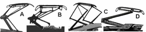
The sketch below shows four types of pantograph designed for use on 25kV services.
'A' Is the Stone-Faiveley single arm pantograph developed in the 1950s, as fitted in pairs to all the original AL1 to AL5 series engines and widely used on multiple units.
'B' is the Faiveley design dating from the 1960s and used on a number of multiple units and (I believe) on some early locomotives. This design had a substantial frame of one inch tubular metal and hence is sometimes called the 'bicycle frame type'.
'C' is the GEC/AEI cross-arm type used on some of the 25kV ac locomotives. The Class 87s were delivered with two of this type and a single Class 86 loco had them as well. A single Class 82 or 83 was fitted with one cross-arm type and one Stone-Faiveley 'A' type for comparison purposes.
'D' is the BR/Brecknell, Willis Pantograph, developed in the mid 1970s, which was retro-fitted to the high speed class 87s (geared up to run at 110mph) and is now used on British high speed units and locomotives as well as on systems in many countries world wide.
Fig___ Pantograph designs
In practice on modern equipment only a single pantograph is used, even on trains where two are available (such as the Pendolino) because the passing of the first sets the wire oscillating and this results in intermittent contact on the second. This is only an issue at high speeds, on the old trans-pennine 'Woodhead Route' line (which used 1500v DC overhead supply) it was normal to have both pantographs raised and on modern services where two or more sets of EMUs operate in multiple it is usual to raise all the pantographs as the speeds are slow enough to allow this. From a thread on the uk.railway newsgroup I gather that the Pendolinos were intended to operate with the trailing pantograph raised, so that if this became damaged, and damaged the wires, the fore pantograph could be raised onto undamaged wire to get the thing moving. Apparently this plan was then over ruled on aesthetic grounds and the units travel with the front pantograph raised when in service.
Non working third rail systems can be modelled fairly easily, one chap I know added a third rail to his OO system by taking a length of rail from some flexi-track and soldering this to dressmaking pins driven into the baseboard beside the track (actually gluing the rail to the top of the sleepers is an alternative approach). Four rail systems are slightly more difficult to model (in N Gauge at least) as the fourth rail, was mounted on insulators along the centre line between the running rails and this is problematic given the tight clearances on N Gauge track. Overhead systems require the production of large numbers of gantries or cantilever arm supports and fine catenary wire arrangements (these latter are available as brass etches, which makes life easier). These are mounted over the track, making cleaning and recovery of derailed stock more difficult. Of the two principal British systems the 25kV option is more difficult due to the complexity of the suspended wire arrangements, which require a lot of insulators and general ironmongery. All this is repeated at frequent intervals along the line.
25kV catenary suspension
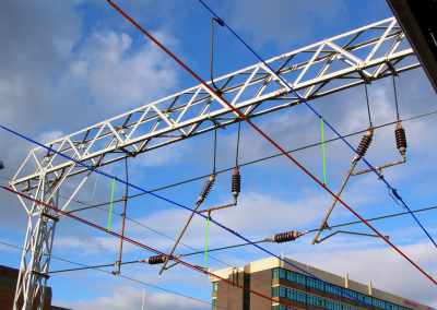
In the picture I have coloured the conductor wire red, the catenary wire blue and the suspension droppers between the two green, this may not be much help as the picture has to be small due to limitations on web space.
The older 1500v DC supplies were rather easier to model with, as a minimum, only a single rather small insulator between the catenary wire and the supporting gantry. The catenary wire often ran over the gantry on the lower voltage systems, the LBSC appear to have used a mast on the top with insulators either side supporting the line, the Heysham line, at least in Heysham station, had the catenary supported on a single insulator mounted vertically atop the gantry and the 1500v DC Woodhead line had some gantries with dropper arms carrying a pair of small insulators with the catenary wire sandwiched between them. The early Altrincham to Manchester 1500v DC system had, at least on part of the route, a curious arrangement with two gantries, one above the other and what appears to be two catenary wires suspended from these, however this is an area I am still researching. Not all gantries were lattice types, a simple I section beam with H section supports was also widely used where the span was small (such as over sections of double track). I hope to put together a more detailed description of gantries once I have gathered enough information.
The old (1960s) Triang OO overhead system employed plastic lattice gantries, the single conductor wire clipped into the underside without the supporting catenary wire. At the time I thought this looked rather good and the electric locomotives had a roof mounted switch to select either two-rail feed or overhead feed. Modern modellers would probably find this rather crude system visually unacceptable.
Battery Electric Locomotives
The
first serious use of electricity for a standard gauge railway locomotive was a
battery powered loco built for the Edinburgh & Glasgow Railway in 1842, unfortunately I have not yet traced an illustration of this locomotive.
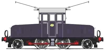
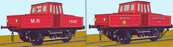
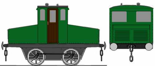
Both the Midland Railway and the North Staffordshire railway owned standard gauge battery operated 0-B-0 (0-4-0 in Whyte notation) engines (at least one each). These appear to be shunting engines, the MR got theirs (number 1550) in 1914, the NSR machine (an identical design) was built in 1917 and was retired in 1963. The sides and front of the bonnet sections are thick timber, probably lined with lead sheeting to protect it from spilt battery acid. I am not sure of the body colour on the MR engine, it may have been black rather than Midland Red. The livery shown on the NSR engine was taken from a photograph which was probably taken in the 1960s. The NSR tended to favour a rather minimalist livery on goods related stock, in earlier years it probably only had NSR on the left and the 'Staffordshire knot' on the right.
Fig___ Battery powered MR and NSR engines
Battery locomotives, including the Midland and NSR engines, tend to be of the centre or 'steeple' cab design and examples have been used over the years at locations where the dirt and red hot cinders from steam engines were undesirable. Not all used wood plank battery compartments, the Lancashire and Yorkshire Railway purchased a battery engine with sheet metal battery enclosures in 1917 for shunting duties at the company power station in Manchester. The battery compartments were probably lined with timber with an inner liner of lead sheeting to protect against leakages of the electrolyte. The photo of the High Level 4mm scale kit shown below is courtesy High Level Models, this 4mm scale model still requires glazing and final painting but shows the detail on the body.
Fig___ L & Y battery powered shunting engine
The sketch below shows an engine built by Hawthorne Lesley & Co in the early 1920s, it has 3ft 3 inch diameter wheels which are connected by coupling rods (unusual on this type of engine), it remained in use in industry at least into the 1960s, possibly the 1970s. The design is essentially the same as the MR and NSR engines but has the metal sheet body similar to that on the L & Y engine.
Fig___ Battery powered industrial engine
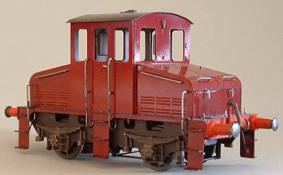
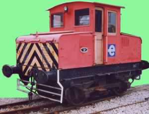
The engine shown below is a preserved example held at the Manchester Science Museum, this engine was used to haul coal wagons and materials about in a Manchester power station, hence the 'electricity board' livery. I have not yet confirmed the build date or employment history of this engine. The white metal bars under the engine are a form of 'cow catcher' to prvent people (or objects) getting under the wheels.
Fig___ Battery powered shunting engine
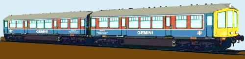
In Britain the only serious 'main line' use of battery power, other than the original 1842 locomotive, was the Ballater Battery Unit, introduced in 1958 and withdrawn in 1962. This was an experimental unit made up of an original Derby Lightweight two car set fitted with about thirteen tons of batteries for use on the Ballater line in Scotland. Hydro Electric power was being produced in the area and this unit was used to test its application to railway services. The set resembled the original Derby Lightweight vehicles but lacked the diesel engines slung underneath and the small grille on the front of the cab. The unit entered service in 1958, had occasional periods of withdrawal for fitting different batteries etc and was withdrawn in 1962 (but may have operated again subsequently (possibly as late as 1965). It was subsequently adopted by the Railway Testing Centre at Derby, renamed Gemini and used for trials of BRATO (British Rail Automatic Train Operation).
Fig___ Gemini Battery Unit
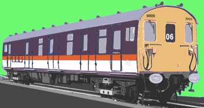
Battery power is also used on electrified lines when the power needs to be switched off. The third rail network around London, and the four rail London Underground, make use of battery powered engineering units. The ferry services from the various ports on the South Coast required regular trains and these tended to be burdened with luggage which had to be moved on and off the ships. The trains themselves could not access the quayside as it would be too dangerous to have third rail systems in such an area. Overhead supply was also ruled out on quays where ships were using cranes to load and unload, the solution was the Motor Luggage Van, a converted Mk.1 brake coach equipped with both third rail pick up and an on board battery pack to allow it to access the quay. Built in the 1950s these units survived into the later 1980s. The sketch below shows the London South East livery (later replaced by the Network South East livery, but not I believe on these units).
Fig___ Battery Electric Motor Luggage Van
Both these units are described in detail in Appendix Three - Passenger Stock - Electric \Multiple Units.
Battery power was also used on some tram systems, this was in the days when a steam tram engine was used to pull one or two passenger carrying trailers. Birmingham had at least one battery tram loco but overhead electrification became the norm.
Pneumatic Systems
In the later nineteenth century there were several experiments using pneumatic power for railways, I. K. Brunel tried pneumatic power on a line in Devon. They used a tube mounted between the rails with a piston attached to the loco by a blade passing between leather strips in a slot in the top of the tube. This worked well but the technology was not up to the job, the leather strips sealing the top of the tube proved prone to failure and Brunel was forced to give up on the system. When the line switched to steam locomotive power the engines found the steep gradients hard going and the service was substantially slower than the pneumatic trains it replaced. In the later nineteenth century one of the London underground lines tried pneumatic power, I have seen drawings of a system running the train itself as the piston in a close fitting tunnel, but this gets problematic in stations and this line may have employed a separate tube and piston system as on the South Devon line. In the event the technology let it down and the experiment was discontinued. There is nothing wrong in theory with a pneumatic system, the 'engines' can be in fixed installations, making maintenance easier and the trains themselves can be simple lightweight coaches as they do not require engines, motors or control gear (other than a brake), but it is a technology that remains unused as far as I am aware.
The alternative approach is to fit the vehicle with a pressurised reservoir of compressed air and this has been done successfully on several street tram lines. The basic idea was to use a large stationary steam engine to compress air which is then stored in cylinders on the vehicles, typically at pressures of about 20 to 30 times the atmospheric pressure. Several examples were trialed in the later nineteenth century, some systems operated a high pressure main supply to outlying filling points and remote depots. The French had the most success (the system in Nantes ran from the 1870s until the First World War, possibly later) but several British cities trialed compressed air trams. London, Liverpool, Chester, Glasgow and even the Wantage Tramway all ran experimental services in the 1880s. The system worked but in Britain they were found to use more coal than equivalent steam-tram services and electric trams were starting to appear. By the later 1890s the compressed air trams had disappeared from British lines.
^
Go to top of page
International Good Guys ~ Making the world a
better place since 1971 ~ Site maintained by

All material Copyright © Mike
Smith 2003 unless otherwise credited