Return to Appendix One Index


Roads and Roadworks


For model railway purposes there are a limited number of details that should be borne in mind. Most towns and villages had roads 20-25 feet wide, the main variation was the width of the pavements, three feet on minor or side streets widening to eight feet or more on main shopping streets. Main roads would be 30 to 35 feet wide, usually with pavements at least six feet wide to either side. Country lanes are all about 15 to 20 feet wide and usually have no pavements. Up to the 1920s everyone used the road, hand carts, horse drawn vehicles and motor vehicles with a fair few pedestrians (although the horse droppings caused most people to prefer the pavements).

Roads in country areas were plain 'macadam', off-white broken stone with a slight camber, in towns most roads were cobbled (photographs below). From about 1905 tarred macadam, smooth and dark grey, appeared in towns, spreading to country roads in the 1930s. Pavements were usually flagged with stone slabs about eighteen inches by two feet, the colour varied depending on the stone, granite being favoured. Kerbs were stone, same colour as the paving slabs. By the 1940s concrete paving slabs appeared and in the post war era became the norm, tarmac pavements were not very common prior to the 1950s, after which they spread quite quickly.

It was common to have quite wide open spaces especially at junctions, as motor traffic increased a lot of the open space at junctions was filled in to simplify the options available to the drivers and reduce accidents. The reclaimed areas were often grassed over but where there were a lot of shops they might be paved. One odd side effect of this practice was that water fountains, municipal clocks and memorials originally located in the centre of the road ended up on an island.

Fig___ Marooned drinking fountain
Marooned drinking fountain on a corner


Historical background

Prior to the arrival of the Romans in 43 AD anything bulky or heavy was moved on boats and the rest was mainly carried on pack horses. Britain got its name from the Romans, derived from the native Celtic peoples the Pritani. To deal with the hostile Pritani the Romans needed good communications and they made a range of improvements to rivers and harbours, they even worked on a few canals as well as building the well known network of roads.

Roman roads were built solidly and followed a fairly straight line. They were military and so avoided terrain which could allow ambush, where the roads passed through a wooded area the land was cleared to a distance of a hundred feet to either side. The main roads were 25 feet wide with drainage ditches to either side and 'services' at regular intervals. Lesser roads were 18 feet wide and had no side ditches.

After the Romans left in about 410 AD the Angles, Jutes and Saxons colonised the country, bringing with them the name England from an area in Germany. Roads and canals require continual maintenance but in the fragmented feudal post-Roman world finding the money and resources was never easy.

The Normans arrived in 1066 and they to set up an essentially feudal system but with a greater degree of centralised authority. To avoid the dangers of some baron raising an army and declaring independence the Norman system granted lands in scattered pockets around the country. One side effect of this practice was that the lords had little incentive to improve the roads as they would gain little by doing so. Over the years wealth based on trade increased, this in turn meant more goods were being moved around the country and the matter of inland transport became increasingly important.

The Highways Act of 1555 placed a formal responsibility for maintaining roads onto local parishes, it was this change in the law that saw roads start to appear on maps. This new arrangement was unfair but more importantly it proved highly inefficient as there was little incentive to build a road to allow people to pass through the parish. A subsequent law passed in 1565 required all parishioners to undertake six days work on local roads every year (the rich could opt to provide a man a shovel and a horse and cart in their place) but there were no proper surveyors resources were limited and road design remained basic.

Bridges were recognised as being too expensive for the parishes to build or maintain and where they existed they were paid for by the County or its sub-division the 'Hundred'. Most goods still traveled on pack horses and most bridges were too narrow to admit carts so in the main rivers were crossed by fords which were dangerous in times of flooding. Cattle and sheep followed their own existing cross-country routes, known as 'droving roads'.

By the seventeenth century the British forests had been largely cut down and coal was becoming important as a fuel. Sea transport was important but coal for London was cart-hauled from as far away as Wigan in Lancashire by the early 18th century. A coal cart could haul about four tons with a team of 8 horses and this meant that coal was expensive. Rules requiring wide wheels to reduce the rutting of the un-surfaced roads had little effect and many roads were often impassible during and after inclement weather.

In 1663 the Turnpike Act was passed, allowing people to set up toll roads. By about 1700 these privately owned toll-roads, operated and maintained by Turnpike Trusts, were bringing some improvement. These were not cheap to build, a typical estimate was for about eight hundred pounds per mile, rather more in real terms than a modern motorway. The turnpikes were in competition with each other, not all were successful and this eventually eliminated many of the duplicate routes between towns and laid the framework of what were to become the 'A' roads of today. The toll gates on the turnpike roads were auctioned, the buyer gambling that the revenue from tolls would more than cover the cost of his bid. In practice although the Turnpikes were originally moderately profitable the costs of maintenance proved too much for the tolls the public would bear. By the later 19th century the Turnpike Trusts were uneconomic and from the 1860's they were progressively closed down, the last (in Anglesey) went in 1895.

In 1835 the Highways Act relieved the parishes of their burden by setting up Districts charged with the maintenance of roads but still gave them no government funding. Pressure on the roads continued to rise and in 1889 the new County Councils were given responsibility for maintaining the main roads.

In 1894 the new Rural District Councils took responsibility for local roads, but it was another ten years before central Government provided any funding for road maintenance.

A Roads Board was established in 1910 to hand out money from central government to be spent on improving the roads. The First World War brought a realisation of the value of strategic assets and a realisation that the British road network was in a state of serious disarray. It was only when a lot of hot air had been expended in parliament that someone pointed out that no one was equipped with either the money or the necessary legal powers to start building new roads. The roads Board was then disbanded, its role becoming part of the remit of the new Ministry of Transport and in 1920 the first of the new roads was started, the Great West Road in Middlesex. This project, in the days before mechanical road building equipment, soaked up a large proportion of the unemployed men in Middlesex.

Between 1919 and 1926 all the roads in Britain received a unique number. It was as part of this process that some roads were effectively abandoned by the local councils responsible for their upkeep. These 'unadopted' roads were left unsurfaced when most roads were being given a tarmac coating. Sometimes only part of the road would be left, usually this was given a covering of red or more commonly black cinders, usually with a lot of pot holes. The street signs on these roads often had a separate plate bearing the word 'unadopted' added beneath, the lettering generally smaller than that on the sign itself. The example shown below was photographed in 2006, in the centre of a built up area but still officially unadopted, perhaps in part because the house frontages are too close together to allow a road proper between them. Obviously the residents had banded together to provide some form of road surface, although this was not as well maintained as the normal roads, and there are street lights as well.

Fig___ An 'unadopted' street in 2006
An 'unadopted' street in 2006

The street with no 'road' as such was more common than you might imagine, although a ten feet wide 'back alley' was still required for the 'night soil' men to access the outside lavatories (shown below left). The example below is sandwiched between another street and a canal, built in about 1863 it remains popular in 2006 in spite of the difficulty in finding car parking spaces nearby as it is quiet and peaceful. Such an arrangement might prove useful on a layout where, as with the prototype, an awkward space needs filling.

Fig___ A street with no road in 2006
A street with no road in 2006

In the early 1920s the government issued instructions to the county councils to improve their road signs as part of the general improvements and provided a set of guidelines on the design in 1921, producing the familiar white and black cast iron finger posts (see also App 1 - Road Markings and Street Furniture). In 1924 when the Government began looking for ways to reduce the high unemployment of the time they began a Trunk Road Reconstruction Program. This brought in investment, allowing contractors and councils to purchase heavy construction equipment.
The sketch below shows a steam shovel on the left, typical of the type in use since the First World War, it is loading narrow gauge spoil wagons (the use of light rail in road construction is discussed below). On the right is a typical mid 1930s 'oil engine' version from the same manufacturer.

Fig___ Steam and motor mechanical shovels
Steam and motor mechanical shovels

By the 1920's secondary 'B' roads were being covered with tarred macadam as well. As noted above it had been found that just pouring tar onto plain Macadam was not ideal, a much better option was to pre-mix the tar and small stone chippings and apply this to the road. The railways transported much of the tarred macadam traffic in the 1920's until the mid to late 1930's, almost all carried in PO wagons, usually no more than three planks high. Digging the tarred chippings out of the wagons to load into road vehicles for delivery was back breaking work, in cold weather it was near impossible, and for fairly obvious reasons this traffic had virtually all transferred to road haulage by the later 1930's. Steam lorries were always the favoured mode of transport as the steamer could heat either the cargo or (more often) the tools (mostly large pronged forks) used to offload it.

The first British dual carriageway (at the London end of the Great West Road) was opened in 1925 by King George V. The first one-way system was introduced at Hyde Park Corner, London, in 1926.

In 1930 the County Councils were given responsibility for maintaining the roads, then in 1936 the Ministry of Transport took on responsibility for maintaining trunk routes. Also in 1930 speed limits on all roads were abolished and the accident rate climbed alarmingly. The Highway Code was introduced in 1931, third party insurance became mandatory in 1932 and the driving test appeared in 1934. The re-introduction of a 30 mph (48 kph) speed limit for built-up areas in 1934 was greeted with howls of protest from the motoring organisations. It is worth noting that the death toll on the roads was greater in 1934 than it was thirty years later in 1964, by which time there were over twelve million cars on the road. Also in 1934 the first 'cats eyes' appeared on British roads, they were not seen anywhere else however as the inventor, a somewhat eccentric Yorkshireman by the name of Percy Shaw, refused to allow them to be sold or made abroad.

The first 'motorway' in the world was built in Italy in the 1920's, in the 1930's the Germans built a large network of modern roads (the Autobahnen), officially to alleviate unemployment but actually as a strategic military network. The British motorway network was first proposed in 1938 but it was 1953 before a definite decision was made to go ahead. The first stretch of motorway in Britain was the Preston By-Pass, opened in 1957 it became part of the M6 in 1963. Originally there were no speed limits on motorways and motor car firms regularly speed tested their new designs on the M1, so did a number of private motorists making it probably the biggest toy ever built by man. Some clot decided to take his new motor for a spin and was clocked at over 180 mph (290 kph) on the M1. Shortly thereafter, in 1965, a maximum speed limit of 70 mph (113 kph) was introduced.

From 1968 all new roads were standardised at 12 feet (3.6m) per lane with a maximum gradient of 1 in 25 (prior to this date the permissible gradient had been about 1 in 30).

The first 'pedestrianised' streets in London appeared in 1964 but these followed an experiment in Norwich. Shopkeepers had been concerned that not being able to park outside the shop would put people off but in the event the reverse was true and 'pedestrianised' shopping became increasingly popular until the 'out of town shopping centres' and giant supermarkets began to kill off the traditional privately owned shops in the 1980s.


Improvements in road construction

Over the years they had been many experiments in road construction, an 18th Century road in Sale south of Manchester bears the name Washway Road, the Washway being a road design having a recessed foundation with outlets at intervals. The theory was that the rain would wash the rising dirt back down through the stones and flush it away through the outlets. In practice this design was not a great success.

In the 1750's Blind John Metcalf (1717-1810, also known as Blind Jack of Knaresborough) although having no formal training began applying a more scientific approach in the North West. He was a violinist by trade, having lost his sight to Smallpox as a child, but he had a deep knowledge of the countryside. He eventually set up as a carter, hauling goods between York and Knaresborough and made a good living at the work. When a local road was to be turnpiked he put in for the job of building three miles of it, selling his cartage business to raise the money. Although he was by this time nearly fifty he spent the next thirty years in the road building business before retiring to a small farm (when he died aged 92 he left four surviving children, twenty grandchildren and ninety great grandchildren). Metcalf pioneered the building of roads over marshy ground by laying a foundation of bundles of reeds and brush-wood. This technique (first used by the Romans) was subsequently used in the building of the first inter-city railway between Liverpool & Manchester where it crossed the great bog at Chat Moss (even today you feel the 'springy' ride on that length of track). Metcalf's roads were concentrated in the areas where the new factories were being built and contributed to the rapid development of modern industrial practice.

In the early nineteenth century a Scot called Thomas Telford (1757-1835) turned from being a successful stone mason and official Surveyor of Public Works for the County of Salop to building roads and bridges. He built a bridge over the Severn not far from the famous Iron Bridge built by Abraham Darby some twenty years before and although almost a third longer Telford's bridge weighed only half as much. Telford used a technique for road building which had recently been pioneered in France, a foundation of carefully cut stone blocks with a gravel surface on top. As the Romans had discovered heavily built roads have their faults but given sufficient maintenance the new roads were a success. Telford was given the job of building roads in the Highlands of Scotland, which had never recovered from the Stuart rebellion of 1745. He also got the job of building the Caledonian Canal between Fort William and the Moray Firth. This work took about eighteen years in all, the roads were successful but the canal never paid for itself. He went on to build the suspension bridge over the Menai straits to Anglesey which opened in 1826. He became the first President of the Institute of Civil Engineers (which received its Royal Charter in 1818) and probably did more than any other to ensure that the profession was recognised. Telford's roads were all about 30 feet wide.

In 1815 John Loudon Macadam (1756-1836) developed his method of road building, he noted that only about a square inch of wheel was in contact with the road and suggested that providing nothing larger than an inch cube was used for the surface the ride would be smooth. To get round the problem of rain making the road a quagmire he added ditches to each side and built the road up into a gentle camber. By adding a top surface of sand and small stones and rolling this down hard he produced a semi waterproof surface that would drain into the ditches. This approach, omitting the sturdy foundation, was cheaper if less robust than Telford's design and after some testing in 1827 the Government commissioned Macadam to build roads all over the country. The spread of 'Macadamised' roads heralded the beginning of the stage-coach era in which road journey times between cities were dramatically reduced and standards of comfort improved. Average speeds on roads reached nine or ten miles per hour, three times as fast as the canals. To supply the broken stone for the new Macadam roads convicts were often given a sentence of 'hard labour', which usually meant breaking up stone with sledge hammers.

Fig___ Macadam road in cross section
Cross section of a 'Macadam' road

In the country areas roads would be typically twelve feet (4m) wide often with a ditch about two feet (60 cm) deep on one or both sides. In remote areas the roads were as little as six feet (2m) wide and these often had no ditch beside them. Horse drawn vehicles always tended to travel down the centre (until the traffic built up to the point where this was impossible) so any pot-holes or ruts in rural areas would be to either side of the centre line even on a wider country lane. On narrow roads and roads leading to farms cars and lorries stuck to the middle and there was often a slight ridge down the middle of the road.

In towns roads were generally wider, typical streets would be perhaps twenty feet (6m) wide whilst major roads would be perhaps thirty feet (9m) wide. Pedestrian pavements were seen in towns and in the shopping areas of country villages in the country and would be two to three feet (60-90 cm) wide on side streets, four to six feet (1.2-1.8m) wide on the more important roads and up to ten feet wide in main shopping areas in towns.

Macadamised roads would be light grey in colour, in British N a coating of fine Chinchilla sand from the pet shop (get the type without the seeds in it) serves well, a wash of very diluted water colour light grey tones down the stark white of the sand. There were a lot of hedges around fields, these were cheaper to set up and maintain than fences, but they tended to grow slightly out of true so in country areas there was often a grass verge running along the side of the road. The hedges can be made using the green pan scourers, cut into strips and teased out to make them thinner and with more holes in them. A good wash with brown and sap green acrylics tones down the very blue-green colour and a dressing of dyed sawdust of scenic scatter materials adds the foliage (with care in painting you can omit the scatter).

Fig___ Photo of an un-tarred Macadam road

Photo of an un-tarred Macadam road

Out in the country on farm tracks and minor lanes there was often a grassy strip up the centre, however this was not present at junctions. The example shown below is a 'one car width' lane, these were quite common in country areas right up to the 1970s and always had a raised centre as the wheels of vehicles wore down the sides. At intervals a wider section was provided to allow vehicles to pass each other (although this did entail someone reversing back to the passing place).

Fig___ Photo of a T junction on an un-tarred Macadam road

Photo of an un-tarred Macadam road junction on a 'country' lane

On farm tracks and works yards the top cover was often black cinders, although these drained through to the ground underneath and tended to form ruts and potholes. There were plenty of cinders available in a country with a large industrial base and although most were plain black or very dark blue I remember a couple of local farm access roads that were covered with red cinders in the 1950s. The red was actually close to a dark orange, there was for many years a slight ridge down the centre of loose material with flat wheel tracks to either side that seemed to stand up to the regular heavy cattle lorry traffic and farm tractors using the road.


Cobbled Roads

In general the towns opted for roads made up of stone sets or cobbles, these did not have the dust problem but although hard wearing the liberal daily deposits of horse manure and urine deposited on it left the surface rather slimy. Horses often came to grief and steam or motor vehicles could all too easily just slide off the side of the road (there is a commemorative plaque in Stockport to a team of firemen killed when their engine on its way to a fire and on a straight section of cobbled road slid sideways, mounted the pavement, went through a stone wall and plunged fifty feet into a valley below). The photos below show the two main styles of cobbled road, on the left is a typical street, note the cobbles along the gutter are set differently and quite visible. The picture on the right shows a small alleyway, note how the single gutter runs down the centre of the roadway, and again the cobbles above the drain are set visibly differently to the main road surface.

Fig ___ Cobbled Road
Appearance of cobbled roads

The German firm Faller offer a 'cobbled' embossed modeling sheet for covering roads however this featured the curved patterns characteristic of Continental cobbles, the British generally laid them is straight rows. For a British layout one option is to take a piece of thick card, say 40thou, and scribe this with the end of a pair of scissors (creating V shaped grooves), then lay 'turkey' Bacofoil or similar thick foil over this and rub down firmly with a scrap of balled up soft cloth. This will actually stretch the foil so it will retain the impression of the 'cobbles', the embossed foil can then be glued down with Evostick or similar. Remember that the cobbles in the gutters are (usually) laid along the road whereas the main body of the road has them laid across the road.


Ken Parkes was able to advise . . .
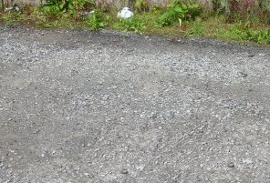
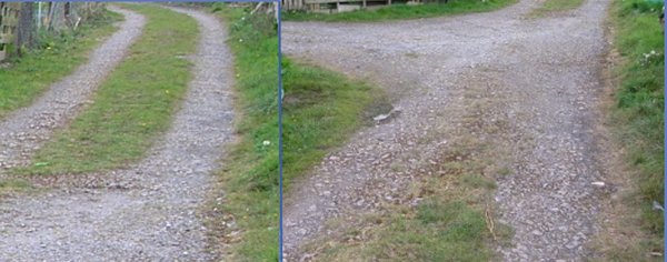
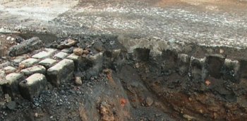
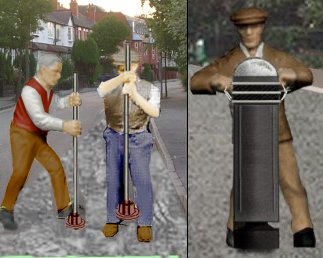
Spherical/ovoid cobbles occur just about anywhere in the north of England/South of Scotland, including under the tarmac outside my house. Except on the coast they are not normally taken from beaches. They were dropped by the receding ice at the end of successive ice-ages, and are dug out of deposits just as sand is. Mostly flattened ovoids, they are laid "on edge". Setts are cubic, and therefore dressed, granite (usually), and are of much more recent development.

At various times between 1832 and about 1860 experiments were made using wooden blocks for the surfacing of roads in London and other towns. The idea came from Russia where blocks were laid with some success at St. Petersburg. From a modeling point of view most of the British experiments had a top coating of tar from the gas works added, so use either 2mm or 4 mm scale embossed brick card and paint it dark grey. Following a discussion on the uk.rec.models.rail newsgroup I understand that there are in fact several examples of wood block paved areas still in existence in various parts of the country. The blocks are about 6" square laid end-grain up, apparently under traffic the end grain seals itself so it doesn't soak in the rain.
Again Ken Parkes was able to advise . .
A lot of the setts in Birmingham were wooden cubes until the 1950s. Quite treacherous in wet weather. Remember seeing them still smouldering in New Street after a blitz. I think they were only used in level areas, sloping surfaces were granite, the irregular edges gave better grip I presume.
Ken.
Regarding the colour of the wooden blocks Tony Clarke, another uk.rec.models.rail regular was able to advise -
Chocolate brown. It took me a while to note that's what they were: the unusual mattness and their being laid in a grid rather than staggered, distinguished them from stones.
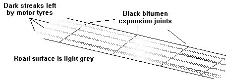
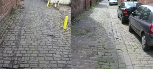
For colouring setts and cobbles in general, micro-variations between grey and dark beige would cover most areas. Granite setts are almost pure grey, but most of the browner hard stones will weather to a pretty nondescript colour, especially dry and in industrial areas, that can readily be replicated from the standard weathering shades and materials. Texture of laying is the thing, as it's rarely utterly geometric unless you're doing modern heritage setting or "best" such as civic squares or main streets - important if doing tram modelling but less so for railway scenery as goods yards/canal towpaths were laid more rustically and soon disfigured from use. Obviously there was a time in any building's life when its floor was pristine, and one might assume that any time pre-WW1 things were better maintained - certainly from official photographs it was: every sett swept, every siding rollered and every ballast shoulder as straight as a ruler! No ash piles or streaked whitewash to be seen when headquarters came to inspect! The Midland Railway seemed especially keen on "spit and polish" in their official material.
Tony Clarke
Modelling cobbles is not too difficult, one modeller working in OO used dried peas set in plaster to good effect. In N you could do something similar using small spherical beads from the local dressmaking suppliers (Singer shops carry a lot of interesting beads, handy for modellers). Alternatively you can lay a bed of Milliput or modelling putty and go over this with a couple of lengths of tubing (squashed to rectangular form) to emboss the depression between the cobbles, tedious but effective. A variation on this idea is to make a sample area using something like plastic metal and let it set hard, then lay thick 'Bacofoil' (the turkey foil is thicker) over this and rub down with a soft cloth. This will actually stretch the metal, permanently embossing the cobbles into it.


Tarred roads

The main problem with the Macadam road was the amount of dust thrown up, even horse drawn traffic caused a major dust problem. At various times people tried applying water to keep the dust down although this mixed with the dust and horse droppings to form a rather sticky mud.

In the 1820's experiments were conducted using cement as a grout on Macadamised roads, producing a form of concrete, but the cements of the day were not suitable, the mix was all wrong and the results were disappointing.

In the 1830's coal tar pitch from the gas works was experimentally applied to Macadamised roads in Nottinghamshire but the idea did not catch on at the time (Macadam himself was dead set against any kind of coating on his roads). It was the 1870's before this was tried on a wider scale but this was still only on short sections of road in towns as a cheaper alternative to cobbles, so road travel outside the town remained a dusty business in summer.

Asphalt imported from Trinidad was used as a top coating on town roads in the 1870's. Asphalt is a naturally occurring material consisting of porous rock such as sandstone soaked in an oily tar called bitumen, typically 10% bitumen by volume. It had been used extensively in Switzerland since the early eighteenth century but failed to catch on in Britain until the 1930s (mainly due to the cost of importing the material).

In 1901 a barrel of gas works tar fell off a lorry outside an iron works near Nottingham and split open on the macadamised road. The workers at the works threw powdery slag over the mess, some time later the local surveyor, one Edgar Purnell Hooley, noticed that the section of road had not deteriorated. Mr Hooley conducted some experiments and found the best method was to pre-mix small stones with gas works tar, laying this on the road and adding more small stones on top. In 1902 he obtained a patent on the method and set up in business as the TarMacadam Syndicate Limited. The product worked and Mr Hooley did well for a few years but then ran into financial problems. The TarMacadam road was evidently a winner and Sir Alfred Hickman, who owned a steel works and had a lot of slag to dispose of, purchased the rights from Hooley in 1905, changing the name of the firm to Tarmac.

Mixing the material on site was found to give inconsistent results so the tarred macadam was prepared separately in large plants and transported to where it was needed. To make this material the stone chippings are placed in a rotating steel drum, early examples were about five feet in diameter and ten feet long, and the heated tar was added to produce the thick porridge of tar and stones. Up to the 1930s the tar macadam was often made at the quarry (usually is a small building close by the railway siding) and transported by rail in low sided (three plank or the steel equivalent) wagons.

In 1903 the speed limit for lighter road vehicles was raised from twelve to twenty miles per hour (32 kph), but heavier vehicles remained constrained to the twelve miles per hour maximum. This increase in speed was in part due to the development of the 'metalled' road (commonly referred to as 'tarred macadam' or tarmac).

There was by this time a Roads Improvement Association, the secretary of which (a chap by the name of Rees Jeffreys), promoted the application of tarred macadam even arranging trials of tar spreading machines in 1907. The widespread use of steam engines for lorries was a boon to the industry as they could use the steam to heat the tarred macadam to make it soft enough to work with.

The application of a top coating of Tarred Macadam to a plain macadamised road reduced the dust in summer and mud in winter, it provided a much stronger surface and the small stones embedded into the top coating provided better grip, eliminating the need for steel studs on motor vehicle wheels. Cobbled roads were also coated, greatly improving the road holding for vehicles. The coating was only a couple of inches thick, topped off with molten tar and small chippings. The sketch below shows such a road under repair, in fact once the work was completed a layer of concrete was put down in place of the cobbles (which were doubtless sold off to refurbishing some very expensive driveway).

Fig ___ Tar macadam on cobbles
Photo showing a section through a Tar macadam road laid on cobbles

Later it was found that a final top dressing of molten tar, covered with small stones and rollered flat, improved the road surface and prolonged its life. This top dressing is not normally bothered with on areas such as car parks, or in side streets, but roads in town and in the country would normally received the top dressing. The small chippings of the top dressing lightened the colour of the road considerably when fresh, this then wore down to a fairly uniform light grey. As road surfaces became worn it was standard practice to add a fresh top dressing rather than re-lay the tarmac (see also road repairs below).

Tarred roads are not black, because of the small chipping laid on the top they start off very light grey, then after a few days they are quite a dark grey colour which then get progressively lighter as the tar is worn off the white stone surface material (if you think about black skid-marks on modern roads you get some idea of how light the road colour actually is). The best stone for tarred chippings proved to be limestone as its porous nature allowed it to key into the tar, as the tar is worn from the surface the white of the stone shows through, producing the ever lightening grey. Roads can be made using black rock such as basalt and these would remain black although I am not aware of any such roads in the UK. Similarly where a red surface is required the top dressing of the road uses a red coloured aggregate, this tends to be expensive and is I understand mainly associated with decorative driveways. When Britain had an extensive industrial base there were supplies of red material (red coloured cinders were used for several 'farm roads' in Cheshire well in to the 1960s), so there may indeed be or have been red tarmac roads somewhere in the country.

The 'roundabout' (technically an 'intersection for gyratory movement'), a French idea, arrived in Britain in 1910, the first was Sollershott Circus roundabout in Letchworth. For the first twenty years after it was built there was no indication of which way people should go, there weren't any accidents but in the 1930s the 'keep left' sign was added. It is now a Grade II protected monument. It was the mid 1960's before the rule giving priority to traffic on the roundabout was introduced. I understand that in Belgium the rule is the reverse, people approaching the roundabout having priority, which has I gather lead to some accidents involving tourists. The 'mini roundabout' appeared in the later 1970s.

Shortly before the First World War a start was made on replacing the old wood-block surfaced and cobbled roads in towns and cities with more modern 'metalled' road surfaces. In most cases the tarred chippings were simply spread over the existing surface. Cobbled streets remained in many places, quite major roads were still cobbled in the 1940's and I remember visiting a Yorkshire hill town where all the side roads were still cobbled in the late 1970's. Some cobbled side streets remained in use into the 1990's. I understand that wood block paving remained in place into the 1950s in some areas, and there are small patches of these still in place in 2006.

In the late 1930's oil refineries began producing quantities of bitumen which gradually replaced the tar from the gas works for producing tarred chippings. Also about this time we began to import bulk asphalt (mainly from Trinidad in the West Indies) for use in road making. This material is applied directly to the road surface, so the 'loose chippings' signs were not required when it was used, however the tar and chippings are still used to add a 'top dressing' to worn sections of roads. These days the process utilises purpose built lorries to deliver both the tar and the chippings. Top dressing work of this kind is only done in high summer as the loose chippings and tar require warm dry weather or the coating does not stick.


Concrete roads

Concrete roads had been built by the Romans and they were tried again in 1865 but the technical problems, and the cost, meant that concrete was little used until the 1930's. When the Great West Road was built they used a foundation of twelve inches of hard core rushed rock covered with a nine inch thick sheet of concrete but this was soon topped with two inches of tarred chippings. The original road was fifty feet (15.2m) wide but they had the foresight to extend the foundations and the concrete slabs to a width of eighty feet to cope with future expansion. A twenty five feet wide grass verge was provided to either side of the road, extending beyond the edges of the road foundations and the sewers, gas, electricity and telephone services were buried under the pavements so that future works would not impede traffic flow. This brought the total width of the road to about a hundred and twenty feet, about ten inches in British N.

Concrete roads are not a continuous ribbon, there are gaps at regular intervals (typically thirty feet or 9m along the road and at the lane demarcations) which are filled with a bitumen compound. These gaps allow the concrete to expand and contract and they are very visible. A concrete road surface is a very light grey with black lines at intervals and there will be distinct blackening where the tyres run. The tyre marks can be created using almost dry paint on a small brush and repeatedly working over the lines to build up the strip. The black lines of bitumen can be represented by coating the edge of a post-card with thinned black paint and pressing this onto the painted road at intervals of about two inches (50 mm).

Fig ___ Plain Concrete Road
Appearance of concrete roads

When building a concrete road the layer of hardcore topped with a sheet of concrete was the standard approach by the early 1930s, however there was actually rather more going on than you might imagine. The underlying hard core could be rock or 'clinker' recovered from industrial furnaces. This was covered with tarred paper (the tar makes the paper waterproof) to prevent the wet concrete seeping down or impurities in the clinker affecting it. The paper was brown on one side, black on the other and was delivered in rolls about three feet in diameter by about eight feet wide. Strips of this paper were laid with a large overlap along the carriageway, covering the full width. Timber shuttering was then put in position and a thin layer of concrete was poured, this was only a few inches thick. Then a reinforcing metal grid was laid, those I remember were made up of half inch steel bar formed into a grid of six inch squares, those I remember had two layers of these. Then the full depth of the concrete roadway was poured into the shuttered box, with steel 'dowels' set into it to keep the individual slabs in line. The top surface of the concrete was them tamped down using a long plank or a light metal frame the full width of the slab. This had handles at each end so two men could repeatedly lift and drop it onto the concrete. By the 1940s there were machines for this job, fitted with large feet and a vibrating mechanism to compact the concrete down. Once the concrete was laid it had to be covered, usually with wet canvass, to allow it to cure for a day or two before the shuttering could be removed.

To provide a better surface for rubber tyres a layer of a few inches of tarred stone chippings was then laid, covered with a 'top dressing' of molten tar and fine stone chippings (this process is described below under 'Road Repairs'). The tarred road surface provides a much better stopping distance and helps prevent skids (very important in the days before hydraulic brakes and more recently automatic braking systems).

In the late 1960's the price of oil and hence bitumen began to rise and plain concrete roads were for a time the standard. The original British motorways had concrete surfaces but over the years these have been covered with tarred chippings as repairs and improvements have been carried out.


Use of concrete and light railways in civil engineering

The use of concrete for producing buildings and roads was not a new idea, in the early 1930s a shortage of bricklayers had lead the Building Research Station and several larger contractors to explore alternative methods of building, however the understanding of the technology was still in its infancy and the preferred methods focused on prefabricated building parts assembled on site, generally with fairly poor results. Pouring concrete into a former was tried, Wimpey's No-Fines, Laing's Easyform and Wates precast concrete slabs were all developed by the named contractors during the 1920s and 1930s as ways of trying to industrialize the building process. They were based around poured concrete construction methods in which shuttering of timber or steel was set up and the concrete poured into this mould to set. The disadvantage of using a poured concrete system was the shuttering was expensive to set up so it only worked if large numbers of identical houses were being built. The shuttering was easier to handle if cranes were used, which was not common in the English construction industry and especially not during the 1930s. Flat roofs were a common feature of these buildings and curved walls were also often added to form bay windows. In practice it was found that concrete buildings were little if any cheaper than conventional brick buildings. The resultant walls were difficult to fix into and to cut accurately, problems were found in sealing the joints and the flat roofs were found to be a liable to leak over time. Following the second world war, during which research on concrete for building work had continued but the prefabricated 'system build' house or tower block remained the most common approach with little use of poured concrete.

Ready-mixed concrete was first used in the USA around the time of the First World War but ready mixed concrete is a heavy material which, unless additives are used, will become unusably solid within a couple of hours, greatly restricting the radius that can be served by a ready-mixed concrete plant. The idea did not catch on in Britain for many years, the first plant was set up in 1931 but there was little interest in the technology until the 1950s. In post war Britain there was a shortage of bricks, and a shortage of coal to fire the bricks, not to mention a shortage of brick layers. As a result concrete was seen as a potentially useful building material, by the early 1960s production had reached millions of tons and peaked in the early 1970s.

The sketch below left shows an early cement mixer lorry, up to the 1960s these had a separate engine for rotating the cement drum. The spit windscreen with wrap round corners date this machine to the later 1950s or early 1960s but similar lorries with an earlier style of cab were operating in the 1940s. By the mid 1970s the lorries were tending to get larger and the drum was larger in proportion to the lorry. The sketch in the centre shows a lorry fitted with a light weight hydraulic mechanism for rotating the cement drum, taking its power from the lorry engine. The cylindrical tank on the top of the turning gear is the hydraulic oil header tank. On the right is a sketch showing the rear of a machine, this machine dates from about the 1990s, note there is a conical hopper at the top, used for filling at the depot, this hopper was introduced (I believe) in the 1980s. Also shown is the feeder channel, this has two sections. In transit the bottom end is folded up and over to rest on the upper section, this is then hinged to lie across the rear of the vehicle.

Fig ___ Concrete mixer lorries
Ready-mix concrete lorries

The preferred alternative in Britain was to mix the concrete on, or very close by, the site. Early cement or concrete mixers were rather large machines with a rather small (to modern eyes) mixing drum powered by a separate steam or oil engine via a belt drive. The all-in-one petrol engined cement mixer was a viable machine by the early 1930s and was widely used in a range of sizes. The larger types were a bit high to be loaded with shovels so they often had a 'skip loader', basically an oblong bucket into which the cement, sand and aggregate could be poured, this was then lifted to load the mix into the rotating drum of the mixer. I have not yet found any suitable photographs of a skip-fed large mixer, the sketch below is based on an American type but serves to illustrate the general appearance. The basic mixing drum shape was the same for most mixers, so it is possible to use parts from a larger scale model to build one of the larger machines. The big machines had four wheels and were towed behind a lorry, the sketch below left shows a mid sized 1930s Lister cement mixer, this would have been towed to the site in the early 1930s, by the later 1940s it would have been fitted with pneumatic tyred wheels but may well have been moved on a trailer if it had to go any distance by road. Smaller two-wheeled cement mixers from the 1940s and 50s were (generally) fitted with pneumatic tyres and had a towing hitch allowing them to be taken to the site behind a lorry. By the 1970s it was common practice to put cement mixers onto a low-floor trailer to allow higher traveling speeds but I seem to remember occasional examples being towed behind a tipper lorry in the 1960s.

Fig ___ Concrete mixers
Concrete mixers

From the start of the road building boom in the 1930s and certainly up to the 1940s (quite possibly the 1950s) it was standard practice on major construction jobs extending over any distance to use a light narrow gauge railway to transport the materials used. Typically these would be 15 inch gauge to two foot gauge and councils hired in or operated fleets of small steam (later diesel) locomotives for use on major road projects. The Leighton Buzzard Railway is currently home to Pixie, a saddle tank 0-4-0 Kerr Stuart built in 1922 specifically for this kind of work.

The sketches below are based on drawings in a book published in the 1940s, however the book in question makes no direct reference to the use of these light rail systems. Replicating such a system might justify the building of a 'new road' on a layout. The tipper wagons have a turntable mounted bucket which was used to pour ready mixed concrete directly into the shuttering as the road progressed. Small 0-4-0 steam engines or diesel engines (with full cabs in the drawings I have seen) moved the tippers along the track. In the earlier stages of construction the spoil would have been hauled away using the classic V shaped side-tipping wagons, these were also used to bring in earth for building up embankments and broken stone for foundations.


Fig ___ Light railway used in road building
Light railway used in road building

For use in road building a battery of large mixers (often of the skip-loading type) would be set up, generally raised on a timber platform to allow them to pour easily into the tipping wagons. The materials would be delivered to the site in road lorries, barrels and later bags of cement would be covered with tarpaulins to protect them from rain.


Road works

Road works offer the distinct advantage to the modeler of bringing the traffic to a halt and suggesting activity. A road works allows a number of vehicles to be included in the scene without them appearing stalled in the road.

Lamps and lanterns associated with roadworks

On the railways a standard piece of kit was the 'flare lamp', a device resembling a coffee pot with a wick stuffed down the spout. The pot was filled with oil and the wick lit, this gave sufficient light for men oiling the inside motion hidden underneath railway locomotives. Flare lamps remained in use on the railways into the 1970's.

Flare lamps were used to illuminate road works at night, usually only two or three lamps would be seen, standing on the ground beside the hole. Flare lamps, also known as 'flamers' were generally replaced in the 1940's and 50's by red painted oil lamps as shown below. There were often quite a number of these supplied as the traffic density had increased. The flare type remained in use into the 1960's for use in foggy conditions where their brighter light was an advantage. In the early 1970's there was a general shift away from red to yellow for warning purposes (following the research done by British Railways in the 1960's) and some of the old oil lamps were then painted yellow. The mid 1970's saw the introduction of battery operated yellow flashing lights at road works, during the decade these gradually replaced the oil lamps.

Fig ___ Roadside Lamps

Warning lamps used at road works


Work clothing

In any road mending scene up to the 1970s there would be large numbers of men at work, even a small job might well have five or six workmen associated with it. From the early days of the railways men working on the roads wore everyday clothes, rather battered and often soiled but typical of the fashion of the times (women were hardly ever seen, those employed in this work wore men's clothing). By 1900 the 'suit' was in vogue and workmen wore a suit of jacket waistcoat and trousers, in warm weather the jacket might be removed but the waistcoat remained on, sometimes unbuttoned in hot weather. The trousers reached up to the waist, the belt (usually a two inch wide heather strap) was typically a couple of inches below the top of the trouser waistband. Shirt collars were separate and not usually worn by working men on the heavy flannel shirts they favoured (usually these had thin blue and white vertical stripes). Up to the early 1950s men often wore a coloured scarf round their neck, in cold weather a scarf (tucked into the front of the jacket) would be worn. In cold or wet wether it was normal to see men working on the roads wearing long overcoats (reaching down to the calf). Trousers were loose fitting and it was common practice from the later 1920s through to the early 1950s to fasten a thin leather strap (or even some twine) round the legs just below the knee to keep the trouser leg loose at the knee and to prevent dust and dirt blowing up the legs. The hats worn by men up to the 1860s were a mixed bag, the two common types seem to have been a wide brimmed hat, made either of soft felt or woven straw, and the cloth cap with a peak (resembling a uniform cap). In the 1860s the flat cap appeared, originally a hat for the sporting gentry but rapidly adopted as a practical bit of kit by working men. Also at this time the bowler hat appeared and became almost a badge of office for foremen and skilled tradesmen. The 'flat cap' remained standard working clothing up to the 1960s when hats generally disappeared.

Fig___ Typical men's working clothing 1860s to the 1940s

Sketch showing examples of typical mens working clothing 1860s to the 1940s

After the Second World War the waistcoat was often not worn but the basic 'suit' of jacket and trousers remained the normal working mans clothing (all men leaving the armed forces were issued with a suit, known as a 'de-mobilisation' or 'de-mob' suit. These were purchased in bulk from selected manufacturers (notably Burtons) but there was little if any 'tailoring' to get them to a reasonable fit, as a result these suits were generally kept as working clothing (this practice has been cited for the growing acceptance of ill-fitting off-the-peg clothing). In the later 1950s the American 'T-shirt', formerly worn as underclothing, became acceptable as working clothing and the 'dungarees' or 'jeans' (trousers made of tent canvass) became more common.

Prior to the second world war men working on the roads usually wore sturdy leather boots with 'hob nails' driven into the sole for grip. After the war, and certainly by the later 1950s, the cheap rubber Wellington boot was the most common footwear, usually with the top turned down to reveal the sand coloured inner lining.

After the second world war the waistcoat quite rapidly disappeared, leaving the jacket and trousers as the standard working man's kit. Boiler suits became more common but the 'flat cap' remained a feature until the 1960s. Dungarees or 'jeans' (trousers made of heavy tent canvass and designed to be hard wearing) appeared from America in the post war era and by the later 1950s were often worn by labourers. The use of jeans as work clothing spread to tradesmen and by the 1980s they were very common, however since that time tradesmen have favoured purpose design clothing made from lighter and harder wearing materials, often with special features such as pockets on the front of the legs for knee-pads (popular with plumbers and electricians).

In cold or wet weather heavy woolen jackets were worn, long overcoats were also seen during cooler periods. Shorter 'car coats' (overcoats ending above the knee to make it easier to get in and out of motor cars) only came in the 1970s, in practice these were a bit useless and one seldom saw workmen using them. Ex army 'greatcoats' were used by workmen throughout the inter-war period and well into the 1960s, a few were seen into the early 1970s (students favoured them at that time but the were falling from favour with workmen due to their weight). In the 1950s the 'donkey jacket' gained favour, this was a heavy woolen coat, black or very dark blue, reaching down to the hip and with black waterproof patches across the upper back and over the shoulders. The donkey jackets remained common into the 1980s.

In the later 1960s or early 1970s workmen started taking their shirts off in hot weather, prior to that the shirt, and often the jacket, remained on however hot it got. By the mid 1970s the shirt, jacket and trousers were generally replaced by jeans, t-shirts, often a thin woolen pullover and (in cold weather) a black 'donkey jacket'. In the 1980s orange 'high visibility' waistcoats were becoming available, however from memory it was usually surveyors and the like who wore these rather than the men doing the labouring work. By the late 1990s the hi-vis jackets were usually yellow and the health and safety rules required the workmen wear safety equipment at all times, plastic 'hard hats' in place of flat caps and steel toe capped boots in place of the rubber Wellington boots. Men working on the roads do not always wear hard hats, with no work above them there is no danger from falling debris, by 2000 men on building sites were always wearing hard hats. In 2005, during a particularly hot and humid spell the road workers were told they were not allowed to remove their plastic 'high visibility' jackets for 'health and safety' reasons.

Fig ___ Men wearing hi vis clothing 2006
Men wearing hi vis clothing


Road Maintainance Scenes and Equipment

Macadam's roads needed regular maintenance as ruts and pot holes formed. Convicts were used to break up stones for road repairs, when demand was high teams of men were hired for the purpose, the larger rocks being delivered to the site of the work where they were broken up with large sledge hammers to get them down to Macadam's required sizes. The local council would pay (usually elderly) men to sit by the roadside breaking up rocks with a hammer to fill-in the isolated ruts and potholes. The pay was not good but the alternative would have been the 'workhouse' (after 1930 the 'Poor Law Institution'), these 'road menders' were occasionally seen at work into the 1940s. They usually wore a hat (as did most men up to the 1960s) and often had the lower part of their trouser legs tied with string, just below the knee, as this prevents the trouser leg pulling on the knee when couching down and stops the dust blowing up their legs.

Fig ___ Road mender
Old man breaking stones to repair a macadamised road

During periods of high unemployment, such as those of the 1920s and 1930s, the local councils would fund road building work to provide a wage for unemployed men. Gangs of four or more men would be dropped off, with a pile of large rocks and some long handled sledge hammers and set to work reducing the rocks to a suitable size for road mending.

In towns there was (usually) a pedestrian pavement at each side of the road (mainly because the roads themselves were liberally covered with horse droppings). In the country there was seldom a pavement as such, usually there was an open ditch at either side as described above, so people had to walk in the road proper. Farmers had to fence in their land to prevent animals wandering and a cheap option was to grow a hedge along the road side. These tended to grow out over the road or field and the ditches often became clogged with brambles and the like. Farmers needed to cut back the hedges and clear the ditches at intervals. Prior to the 1960s this was done by hand, the hedge cutting was done using a five or six foot long pole with a two foot scythe on the end. The man doing this work, either a farm labourer or a self employed hedger, needed thick leather gloves and (certainly into the 1950s) often wore a 'smock' consisting of a sack cut open along the seams to provide arm and head holes. The ditches were cleared by whoever was responsible for the road itself, using a scythe to cut through the undergrowth, and a small hand saw for the thicker stuff, which was then taken away to prevent the ditch becoming clogged and filling with water (which they often did during periods of heavy rain). Oddly enough, although there were many women working on the land, hedging seems to have always been a man's job. In the sketch below left the sack is shown as dark, it could equally well have been a light cream colour, depending on what it had been made for, by the early 1970s it might well have been an orange polypropylene sack with black markings. Where grass needed cutting back, for example where there were wide verges between the road and the field hedges, the standard tool up to the 1950s was the two-handed scythe, a potentially lethal tool with a reputation for causing nasty injury. The example shown below right would serve for any period from the 1920s to the early 1960s, note the complex curve to the long wooden handle.

Fig___ Hedger and grass cutter

Man with hedging tool and sack smock and man using a scythe to clear a grass verge

Either of these offers the opportunity for a little cameo scene on a model railway. In the 1960s mechanical hedge cutters mounted on tractors and powered by the tractor engine appeared, however hand cutting was still occasionally seen up to about 1980.

The technical term for equipment and more especially vehicles used in civil engineering is 'plant', and plant-hire is today a massive industry. Up to about the 1960s the single most common vehicle used was however the wheelbarrow, invented in China about two thousand years ago these appeared in Europe in about 800 AD. Until the later 1930s the most common type was probably the basic wooden barrow although metal barrows were used for jobs such as handling hot coke or tarred stone chippings. To transport the equipment to and from the site the most common equipment was the humble hand cart. As can bee seen in the sketch below when resting on their rear legs these tilted back quite a bit, when on the move this meant the legs were well clear of the ground. To transport heavier or bulkier materials such as stone, tarred shipping or 'spoil' the preferred option was the one-horse cart. Quite a few of these two-wheeled carts were of the 'tipping' variety but a lot seem to have been a simple two wheeled cart with a drop-down tail gate that would need to be unhitched to be tipped (see also App 1 - Road Vehicles - Horse Drawn Vehicles and Bicycles for a photo of the tipping type of cart).

Fig___ Wheelbarrow, horse drawn and hand carts

Wheelbarrow, horse drawn and hand carts


An un-tarred Macadam road relied on being rolled down hard when freshly laid, initially this was achieved using gangs of men hauling a heavy roller with ropes. Horse-drawn road rollers appeared in the 1830's. Steam road-rollers were first used in France in the 1860's and introduced into Britain by Aveling & Porter of Rochester in 1866. Diesel and petrol road rollers appeared in the 1900's, the steam type were generally more robust however and the last were only retired in the 1970's. Petrol and paraffin engined rollers were built by a number of makers, to many and varied designs often incorporating a steam engine like flywheel on the side of the engine. Later diesel powered roller appeared, which were slightly less variegated in appearance and lacking the heavy flywheel. If considering a roller for a wagon load a typical weight for a road roller would be about eight tons.

Fig___ Steam rollers

Colour photos of steam rollers

The steam roller traveled about the place towing a living van and a water cart behind it, the diesel type were usually moved on a low loader trailer. The photos below show preserved living vans, that on the left was photographed at Tatton Park farm, those on the right were photographed at a steam engine rally in 2002 and show how the steps were mounted when the van was parked at the roadside.

Fig ___ Steam roller operators living van

Steam roller operators living van

There have been many and varied designs of steam roller over the years, including 'tandem' types with two rollers and even hand-operated power rollers, these are used for pavements rather than roads and appeared in the 1970s I believe. The illustration below shows an early Aveling and Porter tandem steam roller with a vertical 'coffee pot' boiler and a modern hand operated power roller. Either of these should be fairly easy to model and make a change from the more traditional designs.

Fig ___ Early steam 'tandem' roller and modern hand-operated roller

Early steam 'tandem' roller and modern hand-operated roller

One advantage of having a steam roller on site was that it could be used to power other equipment, notably a stone crusher. More usually associated with quarries (where they were powered by a 'portable' steam engine), one of these might be moved to a site where a substantial section or road required work, for example when preparing to cover it with a tarred macadam surface. The wheels on a stone crusher were small, intended only for moving about on site, they were moved long distances on a low floored trailer. The stone crusher was a simple beast with a hefty flywheel on each side, capable of breaking rocks such as limestone very easily. The loose rock was dropped into the top and emerged at the bottom more or less to the required size. In the sketch below (based on a photograph taken at a steam show) the crusher is in operation and is filling a (rather modern) wheelbarrow. An alternative would be to have the crusher brought in behind a traction engine, which would then serve to drive the thing, as so much of the work was sub-contracted by the council to private firms this was a common solution.

Fig ___ Steam roller driving a stone crusher
Steam roller driving a stone crusher

Road rollers switched over to motor power during the war, by the 1970s very few steam rollers were seen. The immediate post war rollers were similar in size and design to the older steam type. By the 1970s much smaller machines were in use, often these were 'tandem' machines with a full-width roller front and rear. The early small rollers had a fixed rear end with a steering roller at the front (as with the larger machines the steerable roller was split into two sections), by the later 1980s a common approach was to articulate the entire machine with a central hinge and hydraulic rams to alter the orientation of the front and rear sections. The photo below left shows the Matchbox model of a diesel roller, typical of the 1950s, the photo on the right shows a middle sized articulated roller photographed in 2006.

Fig___ Diesel road rollers

Colour photos of diesel rollers

The Aveling and Porter example shown below dates from the early 1980s (the 'C' registration is original), by which time a full enclosed cab was the norm. This machine was photographed in use in 2006.

Fig___ 1980s diesel roller

Colour photos of pavers hopper in use in 2006

Initially tar coating involved pouring gas works tar over the standard Macadam road, this served to reduce the dust but did not provide a very durable surface. The tar arrived in solid lumps and was heated in a large iron bucket on an open fire. The tar was inflammable and the whole thing going up in flames was not uncommon. To transport the buckets of hot tar a barrow would be used, the example below is a general purpose 'road mending' barrow, it has wide wheels to allow it to run over rough ground and a long low and rather narrow body, handy for items such as heavy kerb stones. This odd bit of kit would make a pleasing addition to a road mending scene at any time from 1900 up to the 1950s.

Fig ___ Road mending barrow
Road mending barrow

As noted above a more reliable road surface was produced by first applying a layer of pre-tarred stone chippings, limestone being the best material for the job at the tar bonded well to the stone surface, then covering this with a 'top dressing' of molten tar and fine chippings. A roller was then run over the surface to bed the top dressing into the road surface. The application of the top dressing came in at about the time of the First World War at which time horse drawn rollers were still common (and occasionally used into the 1930s) but the horse could not walk over the hot tar so hand rollers hauled back and fore by gangs of men using ropes remained in occasional use into the 1930's when a steam roller was not available.

The tar coated chippings would be delivered by horse drawn tip-cart or steam or motor lorries with tipping facilities and dumped close by the area to be coated. Men with six pronged forks, heavy rakes and wheelbarrows would then take this and spread it on the road. Metal wheelbarrows were used to transport the tarred stone on site, most wheelbarrows were wooden until the developments in pressed steel in the later 1930s. In the sketch below two types of riveted metal tar barrow are shown, both dating from about 1910. The example in the top right is divided into two so a coke fire in the rear can be used to keep the tarred chippings 'runny' and easy to spread. This barrow also has a frame that allows a tar pot to be heated for 'touching up' the job as described below.

Once the basic coating of pre-tarred chippings had been applied molten tar was added on top, initially by pouring from buckets (as shown in the sketch below) but in 1907 or 1908 four wheeled horse-drawn 'tar boilers' were introduced. These had an enclosed container for the tar, loaded by hoisting a wooden barrel on a small crane attached to the boiler. I believe Langley offer such a boiler in OO but not as far as I am aware in N. The boiler did not need to boil the tar, just heat it up to form a free flowing liquid. The sketch below left shows such a boiler fitted for haulage to the site by a steam or motor vehicle, it has a simple rigid tow bar in place of the horse shafts. The horse drawn type, when in use, had the shafts lifted up and tied off so people would not fall over them. On site the boiler would be parked close by the area to be covered. The boiler was fitted with a hand pump at one end operated by two men (one on each side in a see-saw arrangement) which forced the molten tar down a hose to a man with a 'lance' (a metal tube with an insulated handle at the top end and a spray attachment). A development of this was a boiler with a built-in spray rail on the rear. The example sketched below right uses a chain drive from the rear wheel to power the pump operating the spray, these would require a traction engine or steam roller to haul them along (the example shown is fitted for this) and would be taken to the site behind such a machine. The red flag, hung on the off-side of the boiler would warn other road users that it was in use and there was an engine in front.

Fig___ Tar barrows, bucket and boiler

Sketch of tar barrows, buckets and boilers

Bits that had been missed were then filled in by a man using a 'watering can' with a long spout or a tar bucket (this had a pouring spout and a cover fitted with a hinge allowing the rear to be lifted to drop in blocks of hard tar). The 'top dressing' of small stone chippings was then added, delivered by lorry, moved to the site in wheelbarrows and spread by hand using large bladed shovels. The surface would then be rollered to compact it down.

It is worth noting that molten tar is seriously dangerous in any kind of wind. What happens is that the outer surface solidifies, forming a 'curtain' whilst the inside remains molten and very hot. This envelope of molten tar is then lifted and carried by the wind and if this hit bare skin it would take the skin right off and eat into the flesh beneath, a very nasty injury and not that uncommon. Hence when tar was being applied, either by spray or by bucket, everyone would stand clear, people tended to watch the tar being applied.

Fig___ Road resurfacing

Sketch of resurfacing work

The hand-pump tar boilers remained in use certainly into the later 1950s, quite possibly into the 1960s, so if your layout is 'steam era' the scene shown above would be appropriate. Doing all this by hand was of course a slow business and as road vehicle technology improved more specialised equipment was developed.

Private road maintenance firms flourished in the 1920s as the government poured money into road improvements. The underwriting by government allowed these companies to purchase the expensive road making equipment and rent their services out to the county councils. One popular machine was the steam lorry equipped with a large steam heated tar tank used for tarring roads as part of the top coating of tar and chippings. Heating the tar with steam was much safer than the old wood or coal fired tar boilers (although these remained in occasional use into the 1950s at least). There were a range of designs, the six wheeled Foden 'overtype' lorry shown below seems to use a separate fire to heat the boiler (it has a chimney on top of the tank), this machine was still in use into the 1960s. Tanks were often rectangular on older machines,this may have been an insulated box around a curved tank inside. Some of the older machines appear to have carried two tanks but I am not sure why that should be. On later designs the tank was cylindrical (or by the 1940s oval) in section and the lorry used was typically of the 'undertype' design, this could be modeled using the Dornaplas Thornycroft tanker wagon but there would be quite a lot of work to do on the cab end to convert this to a 'steam' lorry. The tar spraying gear and tank could be removed, several examples exist where the stream waggon was converted to and from tar spraying during its life.

By the later 1940s petrol lorries were in use as tar sprayers, the larger examples, running on eight wheeled chassis, had a platform at the rear for controlling the spray gear, smaller examples had a set of valves on the side of the spray arrangement so a man standing beside the machine could adjust the flow. By the 1940s the actual spray gear was often enclosed in a rubber skirt, suspended from a box arrangement, this was presumably because of the dangers of hot tar being carried by the wind as described above. The sketches are all somewhat provisional as good photographs are hard to find, top left is the Foden overtype, still in use in the 60s. Top right is a Sentinel type (this example was actually in use as recently as the mid 1970s, note the post-war elliptical tank) and below that a 1950s petrol type with a 'crew cab' (not all tar sprayers had such a cab, most did not). One characteristic feature was the pipe extending from the spray boom at the rear to the top of the tank. This allowed the pump to be started with the tar circulating back into the tank, the operator could then adjust the proportion of flow diverted to the spray rail without altering the speed of the pump. On the Sentinel sprayer the pump was mounted half way along the 'off-side' of the tank, sitting on the flat bed of the lorry and often enclosed in a box.

Fig___ Steam and motor road tar sprayers

Sketches of tar spraying lorries

Resurfacing remains essentially the same in 2007, although the vehicles are more modern and the equipment more comprehensive. The scene below was photographed in 2007 and shows a lorry engaged in resurfacing work, there are heated tanks at the rear and a man is using a lance to spray the road surface. Another man was following about with the bucket of molten tar to fill in any gaps. I was the passenger in a car at the time so I was not able to stop and take better pictures.

Fig___ Road tar spraying in 2007

Road tar spraying photographed in 2007

Where a road was simply a bit worn it was standard practice to give it a top dressing of hot tar and small chippings, this exercise would (prior to the 1970s) still require a team of men to do the work, perhaps as few as four but usually more. Where the road surface was in poor condition and developing pot holes it was necessary to re-lay a layer of tarred chippings before adding the top dressing. As manholes and hydrants are cast metal tubes set vertically into the road it was necessary to strip away the road surface, leaving the tops of these protruding, before applying the new tarred chippings and top dressing.

One characteristic of the stone chippings and tar coating process was a large red sign, typically four feet wide by two feet high, with the words LOOSE CHIPPINGS on it in white. This was left in place for a day or so after the road had been surfaced (longer on little used roads) to give time for the chippings to bed into the surface. More recently (late 1990s, possibly earlier) the loose chippings signs have been replaced by a similar sign saying wet tar. The frequency of using loose stone chipping over wet tar may be judged by the fact that a standard European road sign was devised to indicate their presence. This is a warning triangle containing a car with bits flying out from under its wheels.

Fig___ Loose chippings signs


Sketches of Loose chippings signs

A pothole on a tarred macadam road is not merely a depression in the surface, usually the tarred chippings are lifted away as vehicles bounce over the damaged surface, revealing a rim of dark tarmac and a bottom of white stones.

Fig___ Colour photo of a pot hole

Colour photo of a pot hole

The usual method of repair is to fill the hole with tarred chippings until it is slightly proud of the road surface, this is then worn down more or less level by passing traffic. All too often however the area wears down too much, resulting on a dip in the road, this is especially true where a section of road has been dug up to lay sewer pipe, electricity or telephone cables and the like and the ground has compacted after the trench was filled. To help prevent this the infilled area was tamped down, initially by men with a pole fitted with a weight on the end which was lifted and dropped repeatedly. This method was not very successful on roads but remained in use for tamping down pavements at least into the 1980s. By the 1950s a 'powered tamper' was in use which did a much better job. This machine was a five foot tall roughly cylindrical device with a set of metal rings near the top surrounding some vents and a heavy circular 'foot' at the base mounted on a piston. Inside was a single cylinder internal combustion engine. In use the operator pulled a trigger on a semi-circular tubular metal handle near the top and the base was fired down (with a distinctive 'whump' sound), throwing the machine about a foot into the air. By angling the body of the machine the operator could walk it over an area in a series of hops. I have not seen any in use since the later 1980s, however the simple vertical movement would lend itself to a working model, using a cam to lift the tamper at intervals. Running flat out these machines could manage about two 'whumps' a second but it was usual to operate them rather more slowly, firing perhaps once every second or two.

Fig___ Hand and mechanical tamping

Sketch of Hand and mechanical tamping

As the tarmac used on road repairs is fresher than the rest of the road these works are usually visible as a dark patch or strip on the road surface. As repairs accumulate the entire area becomes a patchwork of strips and rectangles of differing shades of dark gray.

A specialised variant on the wheelbarrow was the 'tar barrow', developed for moving tarred chippings about on site. They consisted of a rectangular body, with a sloped front as per a standard wheelbarrow, but had two wheels set back under the body. Having the wheels set back in this way allows the barrow to take more of the weight and the body was about twice the size of a standard barrow. I do not know when these first appeared but they were standardised by the early 1950s, by which time all barrows (other than small domestic types) had pneumatic tyres. The handles on the type I remember were tubular metal formed into a continuous U shape instead of the two separate handles on a standard barrow. The tar barrow was seen at most roadworks and also in a number of construction sites although the two wheels meant it was no good for muddy ground as it could not be run along a plank. By the 1980s the motorised tar barrow was in use at major road construction jobs, although the bulk of the work was by this time being done by large specialised machines rather than men with spades.

Fig___ Post War Tar barrows

Tar barrows

The problem with a tarred macadam road comes when it needs to be dug-up. The surface is hard wearing and difficult to break through with pick axes and the like. The French engineer Germain Sommeiller (1815-1871) developed the pneumatic drill 1861 for tunneling in the Alps. Use on road works required the development of portable compressors but pneumatic road drills were definitely annoying people nearby by the mid 1930s. The early compressors appear to have been substantial machines carried on a four wheel trailer with open sides. The sketch below was made from a tracing of a photo dated '1940s'. The drill supply hose can be seen connected to the machine just behind the radiator, at the rear there is a large cylinder (with flat ends) which is I believe the compressed air reservoir, with the rectangular petrol tank above it. The exhaust pipe was fitted with a hinged lid that covered the hole when in transit, on the machine in the sketch the exhaust was short (the silencer being inside the chassis) but the hinged flap can be seen. Note that in photographs from the 1930s and 40s there seem to have been two men to each drill, a single compressor of this type could support perhaps four drills. By the later 1960s the big four wheeled compressors were falling from use, replaced by much smaller two-wheeled machines, usually with a taper to the top and fold-up sheet metal side panels. By the early 1990s the size was reduced still further and the body was typically a fibreglass shell and usually painted yellow. In the sketch the example on the left would serve from the 1930s to the early 1960s, the type on the right was in use from the 1960s until the early 1990s. The pictures below show a compressor and drill in 2006, by which time the compressor and the drill were both rather smaller than earlier models.

Fig___ Compressors used for pneumatic road drills

Sketch showing compressors

As noted above when a road is resurfaced it is often necessary to strip away the top few inches of road so that manholes will not be affected. This was originally done using pneumatic drills fitted with a spade attachment to break up the road surface, this was then cleared away using shovels and wheelbarrows and taken from the site by horse drawn cart or (later) motor lorry. The illustration below shows the older method with the broken old surface being shovelled into two wheeled carts.

Fig___ Re-laying a road

Shows a road being relaid

One point to note is that, as this is a small shallow hole, there is no fencing as such, only the metal sign at each end of the strip being worked on to warn road users. The ROAD GUARD marking was unusual, a more common marking would be ROAD CLOSED.

By the 1980s specialist machines were in use for removing the top few inches of a road surface so that it could be relaid with fresh tarmac. These are big beasts with a long arm carrying a conveyor belt for the debris extending forwards (the arm can be swung to either side if required but only by a few degrees). This machine, eight feet wide, trundles along at about 2mph ripping up the top few inches of road surface and feeding this into a large tipper lorry in front.

Fig___ Road surface stripping machine

Road surface stripping machine

Where heavy parts, such as cast metal manholes or heavy pipes, had to be lifted into place a simple but sturdy timber crane was built over the hole. These timber hoists remained in use into the early 1930s, although by that time there were traction engines with front mounted cranes and even caterpillar tracked steam cranes available. The snag with these mechanised alternatives was that they occupied road space whereas the timber frame was built over the hole itself. By the later 1930s a small four wheeled petrol or diesel crane was the preferred method of handling heavy parts.

The Second World War provoked a number of major changes to road maintenance practice, in part because of the manpower shortages in the post war era and also the availability of large quantities of ex-military equipment that came on to the market. Prior to the war the vertical boiler steam crane was regularly used at larger work sites, by the 1950s they had virtually disappeared as petrol and diesel powered cranes and excavators of various kinds were sold off by the military. The problems of high pressure hydraulics were still causing difficulties however, so these machines all operated on pulley wheels and cables. The mechanical shovel shown below left is typical of the post war era, when pressed metal body parts were used in place of the wood and corrugated iron for the cab and engine housing. The prototype (on which the sketch is somewhat loosely based) had a 70 horse power diesel engine, to put that in some kind of perspective the Morris 1000 motor car had a 48hp engine. The bucket or 'dipper' has a hinged rear, which can be opened to empty the thing. The dipper is mounted on the 'dipper arm' which passes through a rack and pinion gear which allow it to be moved relative to the jib, an action called 'crowding'. The rack is on the dipper arm and the pinion gear is driven by a chain, this mounting is itself also pivoted, allowing the bucket to swing through an arc (technically called 'digging motion'). The jib itself can be raised or lowered, called 'luffing' and the body of the crane is mounted on a turntable so the jib can move from side to side, called 'slewing'. The small four wheeled crane is typical of the types produced for use by the armed services during the war, this example would probably be able to handle a lift of about one ton. Note the driver has no protective cab at all, if a wheel dropped into a trench and the thing went over the operator was supposed to 'jump clear'.

Fig___ Diesel powered mechanical shovel and petrol engine light mobile crane

Sketch of a mechanical shovel and a light petrol crane

For more information on cranes see also Wagon Loads & Materials Handling - Materials Handling - Hoists and Cranes.

One of the most common machines at the site of any civil engineering work since the 1940s was the 'dumper', a simple four wheeled truck, with rear wheel steering and fitted with a large tipping bucket on the front. These replaced wheelbarrows in a range of duties and were often used in road maintenance transporting materials such as tarred stone chippings on site. I am not sure when this machine came onto the scene, they were certainly in widespread use during World War Two and by the 1950s most building sites had at least one in evidence. They were licensed for road use, and could manage perhaps twenty five miles per hour on the open road, they could be used to ferry tools and equipment between sites a up to a couple of miles apart, a common cargo in this role being a 45 gallon oil drum or two. The dumper was simple in the extreme and the characteristic 'tonk tonk' of the engine is a sound redolent of the post war building boom. The modern equivalent is rather more complicated, the front and rear are hinged so it steers by bending, everything is controlled by hydraulics (you no longer have to haul the bucket back by hand) and for modern health and safety regulations the driver, now seated in the centre, has a protective hood. These days there are also smaller types which have the bucket on a turntable so it can be emptied to the side as well as to the front.

Fig___ Dumper trucks

Sketch of an old and a new dumper

During World War Two there was a need to rapidly build and maintain roads and airfields and a range of machinery was developed for this purpose. The Americans had, since manpower shortages caused by their Civil War, favoured the use of machines rather than people and they produced a range of highly specialised equipment for road building. Examples include the 'grader', a kind of long bulldozer blade suspended under long a four wheeled vehicle and the 'onion scraper' which consists of a large bucket-bodied trailer, the base of which can be lowered to scrape off and gather the top foot or so of earth. The sketch below shows a towed scraper on the left, the lowering of the scraper was controlled by the winch on the towing tractor. Towed equipment was common in the fifties and early sixties but had largely been replaced by self powered designs by the early 1970s. The pre-war graders were also often towed (although the Americans had been using self powered types since the 1920s) but during the war the need for airfields saw fleets self powered graders produced, many of which passed into the hands of contractors after the war.

In Britain the road network had been laid down for many years and completely new roads were unusual and generally only a few miles long. As a result there had not been enough work to justify investment in heavy plant of this type and they were rare in Britain. Another factor was the nature of the roads and the traffic they carried, at the slow speeds of pre war traffic the road followed the rise and fall of the ground and traffic was not unduly affected. As speeds increased a gentle hillock on a long straight road could catch the unwary motorist by surprise, throwing the car upwards, reducing traction and possibly leading to a loss of control and a crash. As a result the new roads built in the post war era have been much more level, requiring greater use of equipment such as graders and scrapers, and these were commonplace where the new roads (especially motorways) were being built.

Fig___ Scraper and grader

Sketch of a Scraper and a grader

Up to the 1960s much of this plant was painted in contractors colours, all-over red and all-over green being common, by the later 1960s all-over yellow was increasingly the norm.

The grader and scraper are essentially road building machines however the associated 'paver', used to lay down the top coating of tarred chippings, is also used to resurface the road after road works. The classic post war machine was built by Barber Greene however fifty years later machines to essentially the same design remain in use. Sizes vary, the photographs below show a smaller fully-tracked type and a larger wheeled version. Note how the front hopper folds inwards (shown upper right) to reduce the width for traveling, this also allows the tar to be fed down into the feed conveyor (consisting of a set of transverse bars) in the centre of the hopper. The post war machines I recall were all wheeled types but rather smaller than the wheeled machine in the photographs (about the same size as the little tracked paver shown in the photographs). In the 1950s these machines all seemed to be painted dark green and were heavily stained with black tar. The examples shown below were in use in 2006 and were generally clean.

Fig___ Pavers

Colour photos of pavers in use in 2006

In use the paver pulled up behind the tarred chippings lorry which filled the hopper, standard practice was for the paver to push the lorry ahead of itself as the lorry emptied into the hopper, but this became impractical in the 1970s as the size of lorries increased and things started to get expensively damaged by this practice. In 2006 I saw a paving operation in which the paver was filled using a mechanical shovel, collecting the tarred chippings from a pile dumped by a (rather large) tipping lorry.

Fig___ Detail of the hopper and rear of a wheeled paver

Colour photos of pavers hopper in use in 2006

The developments in hydraulics during the war and afterwards paved the way for the archetypal piece of road maintenance equipment the 'JCB front loader and rear backhoe excavator', better known as the JCB. J. C. Bamford set up making agricultural trailers in 1945, in the mid 1960s he came up with a design for a tractor with a front mounted hydraulic shovel (technically a 'front loader') and a rear-mounted articulated hydraulic 'backhoe' which became a world classic (this company still has one-in-four of the world's sales in its category). The front bucket can be of various sizes, fitted with chains it can be a handy little crane for moving heavy kit about. The rear mounted backhoe can also be fitted with a range of buckets and is very useful for digging trenches. The backhoe can also carry a hydraulic drill, a steel spike repeatedly hammered by a hydraulic drive and used to break up road surfaces in place of the man with pneumatic drill (but just as loud).

Fig___ JCB

Colour photo of JCB in 2006

Prior to the JCB era the tractor mounted shovel was not common at roadworks, although steam and diesel excavators had been used on larger jobs since the 1920s. Sketches of the pre-hydraulic 'front loaders' will be found in the section on Railway Company Goods Facilities - Coal, Coke and Heating Oil as these were used in coal yards.

By the 1970's tipping lorries were getting very large and by the later 1980s a hydraulic crane was a standard fitting on many of these. The articulated arm of the hydraulic crane was by this time used for a wide range of tasks, doing many of the jobs formerly done by men with shovels and wheelbarrows. The photographs below show kerbs being replaced, with only about five or six men on site. Prior to the introduction of the hydraulic equipment a much larger team of men would have been needed. Firstly the pavement was covered with tarmac, so this would have been broken up with pneumatic drills (or from the 1950s electro-pneumatic 'kango' drills). Then the old kerb stones would have been levered out using crowbars and carried away on wheelbarrows to be collected by a lorry. Then a team of 'precision diggers' would have dug the trench for the new kerbstones, and a lorry would have dropped off a pile of sand which would have been collected in wheelbarrows and used to fill the trench to the required depth and tamped down with hand tampers. Men would then have lifted in each of the stones, using big rubber ended hammers to get them correctly aligned. Finally a tipping lorry would deliver fresh tarred chippings which would be collected by men with wheelbarrows and used to fill in the pavement side of the kerb.

In 2006 the big tipping lorry arrived with the new kerb stones and a few tons of sand, using its hydraulic grab to place the sand in piles and the kerbstones close to where they would be used. The four wheeled hydraulic digger then arrives and lifts out the old kerbstones, dropping them into the now empty lorry. This machine also digs the trench, widening the hole left by the old stones and dumping the waste into the lorry. It has enough power in its arm to break through the existing pavement surface. One man with a spade and wheelbarrow collects the sand from the piles and back-fills the trench. When a length of road has been prepared the hydraulic digger is used to lift the new kerbstones into the trench and nudge them into position. Finally the new tarred chippings arrive, the delivery lorry can use its on-board crane to place this into the trench, requiring the men to level it out.

Fig___ Replacing kerbs in 2006

Kerb replacement in 2006


Fencing and barriers at roadworks

At larger sites standard practice was to have a watchman on duty, during the night and sometimes during the day as well. Prior to the Second World War it was common practice to have a small 'sentry box' type timber shelter and a braiser (a steel drum punched with holes to contain a coal or coke fire) so that a night watchman could keep an eye on the tools and other equipment during the night. The night watchman became increasingly rare in the 1960s as the general shortage of labour brought higher wages and I do not remember seeing one in the 1970s. In the sketch below, based on a photograph taken in the 1930s, the green 'corporation highways department' hut can be seen with a small braiser in front of it. In the photograph there were no warning signs in evidence, nor any form of protective barriers other than (what appears to be) an oil drum full of rubble just beyond the hut. One point to note is that the hut has been placed on some rubble, so the base is not flush with the road surface, this tends to happen on a model anyway but in this case you do not need to worry too much about it.

Fig___ Night watchman's hut and brasier

Night watchman's hut and brasier

Obviously where roads were dug up to lay underground pipes and the like there was a danger of people or vehicles falling into the hole, especially at night. In towns it was common to set up a timber fence around the site, for a big hole or a large job a high palisade was often set up, perhaps eight or nine feet high made up of wide planks nailed to timber supports. This also allowed the equipment to be left safely on site. In the sketches below the example on the right has been whitewashed as an additional safety precaution. Having discussed the photographs on which these illustrations were based with an experienced 'ground worker' I gather that on the left they were probably fitting a cast metal manhole, on the right they appear to be re-lining a sewer with new bricks.

Fig___ Fenced in roadworks - 1900 to 1930s

Fenced in roadworks - 1900 to 1930s

As can be seen the site could be closed off using a removable or hinged section of fencing to protect equipment during the night.

Where a small hole was dug in a road a simple sign at each end of the hole was all that was required, road traffic, especially outside the centre of town, was so light that accidents at roadworks were not commonplace. For a smaller job, especially outside the towns, it might only be a simple barrier of red painted planks supported on timber posts mounted on a wooden X frame. By the 1930s one commonly used option was to drive a steel post perhaps four feet high into a timber plank, the plank was laid on the ground with a few bricks or cobbles resting on it and a rope was strung between the posts to 'fence off' the area. This approach was useful where a cobbled road was being worked on as it is not possible to drive the posts into the cobbles. The chap on the right, bent double and chipping at a cobble stone, shows how this kind of work was done, it must have been backbreaking work.

Fig___ Fencing at roadworks from photographs

Fencing at roadworks from photographs

By (I believe) the mid 1930s five foot long metal rods with a small U shaped bend at one end were commonly set into tarred macadam roads and a rope strung between them, by the 1950s this was the standard way of fencing off road works as the pneumatic drills could punch suitable holes in the road surface. Sometimes scraps of red bunting (a light cloth used for making flags) were tied to the rope. In the illustration below the trench is protected by these posts and ropes, at each end there would be a rectangular warning sign, typically two to three feet wide by two feet high saying something on the lines of DANGER ROAD WORKS in white lettering on a red background.

Fig___ Post and rope fencing at drain laying site

Post and rope fencing at drain laying site

By the 1950s the red oil lamp, described above, was in plentiful supply and every road works site would have at least half a dozen of these, often they were laid in a line on the road beside a trench, or suspended from the metal poles supporting the rope. Those on the road itself, even when very close to the edge of the trench often got driven over, so the odd flattened example would be prototypical. These were also hung on the side of plant such as compressors or generators left on site to help motorists avoid them at night. Another simple expedient was an empty oil drum filled with rubble, sometimes painted red with a white band around the centre but often just an old rusty brown drum with a white band or the remains of an overall coat of white paint. These were placed on the approach to the site, to prevent motorists driving straight into the trench or work area, I do not remember seeing any used along the sides of a site for protection. The earliest photograph I have seen showing one of these was taken in the 1940s, they may have been used in the 1930s but I suspect the drums were then too valuable. These drums were also used to support signs mounted on a single post (notably the 'site entrance' sign guiding arriving delivery drivers) and I recall once seeing an electric road works traffic light mounted on a post sitting in such a drum.

In the later 1950s one fairly common piece of kit was a folding tripod made from 2 inch (50mm) diameter metal pipe, bent at the ends and fastened together with a steel pin. They could fold flat for transporting, the lower part of the tripod was painted red, the top ends white. They could be used to support a painted plank of wood as a barrier but were often seen standing alone, although they were handy for hanging a workman's jacket on. By the 1970s the red bunting on a plain length of rope slung between the steel posts was considered not sufficiently visible and a lightweight 'ladder' strip of red or orange plastic was used. This was about eight inches wide and supplied on long rolls. Traffic had built up considerably by this time and there tended to be more signs and oil lanterns sitting on the roads to warn motorists of the hazard, the triangular sign 'man having trouble with an umbrella' appeared as part of the shift to a Europe wide standard set of signs after 1967. The traffic cone appeared on British roads in the 1970's and by the 1990s a new bit of plastic kit arrived in the form of a simple barrier. This has a white tubular post sitting on a moulded red base and has a top cap fitted with sockets into which a plastic horizontal bar painted in strips of white and red can be fitted. These are mainly used to provided a protected walkway for pedestrians on the road where the pavement itself is being dug up.

Fig___ Folding metal and plastic barriers

Folding metal and plastic barriers

As more machines became involved in road maintenance, notably cranes and tipping lorries, the high palisade fence was more of a hindrance and moveable barriers came to be the norm. At larger sites fencing was still required for security, the timber wall remained in evidence into the later 1960s, often incorporating old paneled doors but by the 1960s many building sites favoured tubular metal frames with a light metal mesh, those I remember were about six or seven feet high. In the building boom of the 1990s and early 21st century the profit on buildings was sufficient to allow the mass production of fencing units.

There was no standardisation regarding barriers and fencing, almost every photograph I studied showed a different approach.


Warning signs associated with roadworks

There were a number of warning signs associated with road works, however as most of the work was sub-contracted to private firms there was little standardisation prior to the Second World War. One common sign was a red painted board perhaps four feet long by six inches high with ROAD CLOSED on it in white capital letters, on some signs the background was white with red lettering. These were supported on timber posts set on a timber X frame, or had legs permanently attached (as in the example shown below, note the sand bag on the base to prevent the wind blowing it over). By the 1930s a variant was in use with a light metal supporting frame, although this did require a sandbag or two to hold it in place. These 'road closed' signs were used even when the road was not closed as such, only a strip was being worked on. A variant on the was the same metal folding sign but marked ROAD GUARD, this marking was not common (and may have been a regional anomaly), an example is shown above in the illustration of men removing the old tarmac surface ready for re-laying the road. Following the war sheet metal signs were produced for sale or hire and a standard red background with white lettering was adopted (this had been fairly standard beforehand). Probably the most common sign in use was a large rectangle painted red with ROAD WORKS AHEAD written on it, up to the 1960s this sign might be only a few feet from the men working but where the works were hidden by a corner the sign was usually positioned before the bend. The example shown below has glass reflectors embedded into the letters, called Mur-Rays these were introduced (I believe) in about 1940.

Contractors still used their own signs however, the white wooden sign with raised lettering was sketched from a photo dated 'early 1950s'. The sign was propped up against a lamp post close by a rather deep hole in the road, with only a couple of red oil lamps around it as protection.

One odd sign was 'RAMP AHEAD' or 'SLOW RAMP', indicating a change in road level, usually covered by a heavy steel sheet. This was (from memory) mainly associated with work done on bridges where the approach ramp to the bridge would have a set of steel plates laid on it, although timber strips might be laid there would still usually be at least a one inch 'step' in the road.

Folding wooden signs were in widespread use by the 1940s, and remained common into the early 1970s, often the sheet metal signs were screwed to these as their weight made them more stable and less likely to blow over. Following the introduction of the continental warning signs in 1967 some of the old wooden type were re-painted all-over red and had the new style metal sign fixed to them (being heavier they were less likely to get knocked over by wind or the draught from passing traffic). By the mid 1970s the triangular metal signs were usually supported a lightweight metal frame support, again this required a few sandbags to hold the sign in place. The growth of car ownership has seen a move away from technically proficient motorists to a preponderance of less capable car operators and the modern metal signs tend to get driven over a lot and are often rather bent and battered. Since the later 1970s there has been a proliferation of warning signs associated with major road works or other civil engineering jobs, most warning road users of hazards, some offering guidance to visiting vehicles.

Fig___ Warning signs from photographs

Warning signs from phtotgraphs


Traffic Control Signs and Lights

By the early 1930s a standard bit of kit was the 'stop-go' sign, a light metal disk showing a red face with stop or a green face with go, the lettering being white. These were used where one half of a road was occupied so traffic had to take it in turns to use the remaining half. There were two types, the simplest was a pole with the double sided disk on top, typically two feet in diameter. If the section of road affected was longer than about a hundred feet two men with stop-go signs would be used. There was a more sturdy type, consisting of a disk supported on a tripod with a hinged semicircle, this could be lowered to show stop or raised to show go as required. Both types of sign required a man to operate them but the tripod type was easier to handle on a windy day and did not require to man to stand there holding it. The tripod type were handy on country roads where traffic was sparse, they could be erected at either side of the job and set to stop. Then when a car turned up a man could walk over and change the sign at that end to go. In the 1930s red and green electric traffic lights mounted on light metal tripods appeared, running on battery power, by the 1960s these were more common and usually powered by a small generator sitting close by on the road (this produced some odd voltage so there would be no point in people stealing it). The stop go signs were still occasionally seen into the 1980s but the traffic lights became the norm, modern versions use low energy LED lights and are powered by a battery pack in a two wheeled trailer and charged using a solar panel mounted on top of the trailer. The sketch below was based on a photograph taken in the 1930s, note the hand painted sign. A more common sign associated with lights of this type was seen from the 1940s, as shown on the upper right below. From 1967 the new standard sign for road narrows was also required, as shown in the lower right below.

Fig ___ Traffic control signs and battery lights

Traffic control signs and lights

For those interested in such matters the website of the Road Roller Association might be worth a visit. The last time I visited they had not set up their gallery page but when this arrives it may well offer some useful pictures of road works and associated equipment.


^
Go to top of page


International Good Guys ~ Making the world a better place since 1971 ~ Site maintained by Disabled Access to Computing
All material Copyright © Mike Smith 2003 unless otherwise credited