Return to Appendix One Index


Engines and Prime Movers


Engines

A key element in the Industrial Revolution was the application of wind, water and steam power to drive machines. It is perhaps worth noting that in the mid 1980's about half the world was still solely dependant upon human or animal muscle power. Even in Britain horse powered systems remained in use in to the middle of the twentieth century, mainly on farms and at smaller mines and quarries.

The most common horse engine was the 'gin' (a shortened form of 'engine') or 'whim', a capstan fitted with a long arm to which the horse was harnessed. The horse walked round and round and the capstan could either wind up a length of rope to pull trucks along a plate-way or, via gears, drive a shaft to power a small mill or machinery such as a corn threshing machine (invented by Andrew Meikle in 1784).

Where these horse powered gins were used at mines and the like they were usually in the open, on farms, where they powered fixed threshing or milling equipment, they might be enclosed in distinctive circular buildings. By the 1990's there were very few of these buildings left in existence. There is a very nice model of a portable gin on the Pendon Museum 'Vale Scene', it is hooked up via a rigid shaft to an elevator being used to build a hay stack on one of the farms. The example shown below is a type that was mounted inside a building, the horse would be attached to the harness on the left. This example can be seen at the Manchester Science Museum.

Fig ___ Horse power
Horse whim at Manchester science museum

The example shown is identical to one used at a mine in the early nineteenth century, however I would doubt that mines would have used these after about 1850.

Windmills were developed in the Middle East and only arrived in Britain in the thirteenth century. They are primarily associated with the eastern counties of England, to the east of a line from the Trent down to the Severn but there were isolated examples in most parts of the country.

There are two types of windmill used for grinding corn, the post mill, which has a central post on which the whole building is turned to face the wind and the tower or smock mill, which has the sails mounted on a rotating top section called a cap. Tower mills were built of brick or stone, smock mills and post mills were built of wood. These windmills provided about sixty horsepower in a stiff breeze.

Fig ___ Windmills
Sketch showing typical windmils of the post and mock type

The tower or smock type of windmill was also used for driving wood cutting circular saws and other light industrial tasks. In the 1970's many windmills were restored to working order, a restored post mill similar to the well known Airfix kit in 4 mm scale can still be seen at Wraby, near Brigg in North Lincolnshire and a similar mill operated near Liverpool up to about the time of the First World War.

Fig ___ Windmills internal workings
Sketch showing cutaways of typical windmils of the post and mock type

a Fan to keep sails into the wind. b 'Trundle' connects drive to vertical shaft c Feed hopper d Receiving bin for flour e Gearing, vertical shaft to base of mills stones f Mill stones g Arm for turning the post mill into the wind h Base and central post i Levers to rais and lower stones j Toothed wheel on shaft of sails k Shaf for sails l 'Basket' a simple form of wooden bevel gear to transmit power from sail shaft to the stones m Mill stones. Faller offer a smock mill (2250) and Kibri offer a kit of two post type mills (B-7132) which are sufficiently generic to be used in a British setting. The photographs below both date from the 1920s and show (left) a Cambridgeshire smock mill and (right) the base of a Suffolk post mill, the scans were taken from a tourist book published in the 1930s.

Fig ___ Windmills in use in the 1920s
Sketch showing typical windmils of the post and mock type

Windmills of lighter construction, typically a light metal framework tower topped with a multi-bladed propeller, were widely used for pumping water, either draining flooded land or lifting water from wells. An OO scale etched brass model of the standard agricultural windmill, used for pumping water, is available from ScaleLink. The top section of this could be mounted on a small circular building to represent a larger Victorian 'pump house'. These were not common however and they need to be mounted on a piece of high ground.


Water wheels were used by the Romans but fell from use when they left until about the eighth century. The number of water wheels then steadily increased until by about the thirteenth century most villages had at least one water powered mill for grinding corn. Later water wheels drove the bellows in the iron works and the spinning machinery in the textile mills, water wheels are more reliable than wind power although droughts and dams could affect their use.
The British Engineer John Smeaton (1724-1792) did a lot of work on water wheels and proved that the over-shot wheel, driven by the weight of the water, was more than twice as efficient as the undershot type then in common use, which is driven only by the flow of the water.

The first all-metal water wheels were built in the 1830's and they gradually displaced the wooden types as these fell due for renewal.

XXX Info on Laxey wheel XXX

Water powered installations have certain characteristic features which identify them even when the wheel itself is mounted inside the building.

Fig ___ Water mill
Sketch showing typical water mill


Water turbines date from the early nineteenth century when a French engineer called Benoit Fourneyron built a horizontal high speed water wheel. This is the earliest example I have found of a ball bearing, used to carry the shaft to allow high speed operation, the balls were made of marble and ran in wooden tracks. Fourneyron went on to build over a thousand turbine installations all over the world and Fourneyron turbines are still used today where there is a low pressure flow of water such as a river. In 1889 (following ten years research) an American engineer called Lester Allen Pelton (1829-1890) patented an improved design known today as the Pelton Wheel. This is the turbine used for high pressure water turbines which are used where a high head of water is available such as at a waterfall or a purpose built dam. Pelton turbines are employed in hydro electric power stations. Hydraulic engines and rams were only developed in the mid Nineteenth century, these machines are discussed below. Water power used to drive simple mechanical devices continued in use into the twentieth century but as steam engines were improved they became increasingly popular and steam remained the major source of power into the first half of the twentieth century.

Steam engines were developed partly because of the shortage of water supplies to drive water wheels. This was most notable in Cornwall where there is little surface water, and it is no surprise that so many of the pioneers of steam power came from that part of the country.

A French inventor called Denis Papin (1647-1712) produced the first piston engine in 1690. His engines was too inefficient to do practical work but the idea was later taken up by others, notably the Englishman Thomas Savery (1650-1715). Savery patented a primitive steam engine for pumping water from mines in 1698, called 'The Miners Friend' it was a simple design and was rather prone to exploding. The engine worked on air pressure, steam was blown into the cylinder which was then cooled. This condensed the steam causing a partial vacuum and the air pressure pushed the piston into the cylinder. Thomas Newcomen (1663-1729) a blacksmith and inventor developed an improved version of this engine when working with a John Cawley. Newcomen subsequently went into partnership with Savery and their firm introduced the first really practical steam engines in about 1712. The Newcomen engine was not terribly efficient but the same basic engine remained in use into the nineteenth century, partly because of the charges levied by the patent holders on more advanced designs.

In 1775 John Wilkinson, a Staffordshire iron maker, developed a practical boring machine able to bore a near perfect circular hole in solid metal. This was a major advance when applied to steam engine cylinders, the resulting cylinder was much stronger than the earlier designs based on riveted plates but more importantly as it was accurately drilled it did not leak nearly as badly. Newcomen's pistons had to be up to two inches smaller than the cylinder and leather washers were used to form a seal.

James Watt (1736-1819) patented his improved steam engine in 1769, this had a bored cylinder with a close fitting piston and there was a separate condenser connected to the cylinder, allowing the cylinder to remain warm when the steam was condensed. In the mid 1770's James Watt and Matthew Boulton (1728-1809) set up in partnership at the latter's Soho works near Birmingham and started producing steam engines. In 1780 Watt built the first steam powered flour mill and in 1782 he invented the double acting cylinder, in which steam is admitted at alternate ends to drive the piston in both directions. In 1788 Watt invented the flyball or centrifugal governor which uses two weighted arms mounted on a rotating shaft connected to the engine. As the speed of the engine and hence the rotation of the shaft increases the arms tend to fly outwards, this motion is then linked to the steam valve to bring the speed back down again. This meant that engine speed would be maintained with changes in temperature in the boiler and with varying loads, amongst the first examples of feed-back control systems this simple mechanism remains in use today.

Fig___ Fly ball governor principle of operation

Fly ball governor
The example below is typical, this one is on a machine at the Manchester Museum of Science and Industry.


Fig___ Fly ball governor

Fly ball governor


These early steam engines were still large and not terribly efficient however and they were mainly used to pump out water from mine workings. Watt was still using low pressure engines operating at only a few pounds per square inch but by this time interest was growing in the idea of higher pressure steam engines which used the steam pressure to drive the piston directly. A Cornish mining engineer called Trevithick developed steam engines which used much higher pressures than the Newcomen/Watt types, originally intending to build engines for pumping water out of the Cornish tin mines. He went on to build a steam powered road carriage (in 1801) and a steam locomotive (in XXX).

The design of the steam boiler evolved slowly. Early engines used a curiously shaped container made of riveted plates called a 'haystack' boiler. This was based on the kettle of the day and had sides which sloped inward toward the bottom to increase the area in contact with the flames. Next came the cylindrical boiler, often called a 'wagon boiler', again this was heated from below and was not terribly efficient but it was easy to make such a boiler mobile.

The next development introduced a pipe through the boiler, the hot gasses from the fire were lead through this pipe to heat the water, this was called a Cornish boiler. Fitting fire bars to the boiler itself (the fire was actually inside the boiler) produced a self contained unit that proved popular as a heating boiler. Adding a second tube produced the self-contained 'Lancashire boiler' and this proved a reliable and easily maintained option for industrial use. These are of particular relevance as many were later converted to serve as water tanks for industrial stream railway systems. All you need is a tube ten to twenty millimetres in diameter, add flat ends and two discs punches with a leather punch at each end to represent the blanked-off fire tubes.

Fig ___ Cornish and Lancashire Boilers
Cornish and Lancashire Boilers
The 'Scotch boiler' had multiple tubes through which the hot gasses were passed, this raised steam more quickly and enabled higher pressures to be obtained. In spite of its name it was originally developed by a French engineer called Marc Segun (1786-1875), this type became the standard design for steam ships and railway locomotives.

By the 1950's new ways of burning the fuel were being developed and there was a shift to putting the water in the tubes, producing the 'water tube boiler'. This type of boiler generates steam very quickly as you do not have to heat the whole boiler up to temperature to start, but it is only economical in applications where you will use a lot of steam such as in power stations.

In 1807 an American called Robert Fulton (1765-1815) built a successful steam powered ship, this was not the first steam ship but it was the first to be a commercial success. In 1819 the American sailing ship Savannah used an auxiliary steam engine in her crossing of the Atlantic. Passengers generally preferred the peace and quiet of sail, the noise and vibration when the steam engines were used was reportedly most annoying.

Robert Stephenson (1803-1859), with his works at Newcastle, was probably the most influential locomotive engineer of the time and his father George Stephenson (1781-1848) was one of the strongest advocates of steam-hauled railways. George Stephenson was appointed as the engineer for the Stockton & Darlington Railway of 1821, built primarily to carry coal this was the first successful 'public' railway to use steam engines. Passenger traffic and some of the goods traffic was handled by sub-contractors with their own stock, all of which was horse drawn. The photo below was scanned from a book published in the 1930s, the photo was taken at the Centinery exhibition on the line in 1929 and shows a replica engine built for the occasion which proved capable of speeds of up to 12 miles per hour when pulling a full load. The telegraph pole with its bank of insulators would not have been present when the original engine was in service.

Locomotion No.1 replica on the Stockton and Darlington line


Steam railway locomotives remained ungainly and unreliable machines mainly developed for use on short runs in collieries but progress was rapid. A horse could pull typically four coal wagons at about three miles per hour (5 kph), by 1830 steam locomotives were pulling upwards of twenty wagons at anything up to twenty miles per hour (32 kph). In 1830 railway engines developed from the successful Rocket began operating on the Liverpool and Manchester Railway and soon proved their worth.

In 1845 William McNaught (1813-1881), an American, invented the 'compound engine' or 'double expansion' engine in which the steam is first used to drive a high pressure cylinder, then re-used to drive a second low pressure cylinder. It was not long before a third cylinder was added, producing the 'triple expansion engine' . These were not initially very successful but when forced draft ventilation of boiler fires was introduced, greatly increasing the pressure of steam produced, they became the engine of choice for steam ships. Some years later various railway companies built locomotives with two-stage 'compound' engines, one example being the Midland Railway 4-4-0 as offered by Graham Farish. This locomotive has two cylinders mounted on the outside as normal but with a third (high pressure) cylinder hidden underneath and connected to a cranked axle on the leading pair of driving wheels.
In 1859 William Rankine (1820-1872) produced the first comprehensive manual for steam engine design.

There are several commercial 'boiler houses', complete with chimneys, available but in some cases additional structures are required to house the primary machines that powered the rest of the factory using rotating shafts and belt-drives.

The boilers would often be housed separately from (although usually close by) the cylinders that powered the large flywheel, which in turn drove the iron rods running through the building to turn the local belt-drive on the machines. These wheels were really impressive things, there are several on display at the Manchester Science Museum and the last surviving steam powered cotton mill (Queen Street Mill, Harley Syke in Burnley, Lancs) is now a working museum. These engines used coal for fuel, so you will need a stockpile somewhere close by.

Where power was required to be mobile a 'portable steam engine' was a popular option. This machine resembled a steam traction engine but it was towed from place to place. They were often used on farms for driving machinery such as threshing machines into the late 30's, and some were still in use driving stone crushing plant in quarries right up to the 1940's. The pistons, flywheel and power take-off shaft for belt drive were all mounted on the top of the boiler.

In a small works a redundant steam boiler from a locomotive might be used, often this was housed in a rough and ready structure close to where the steam would me used. As an example a wood yard might have such a boiler for operating a steam driven circular saw which justifies the occasional coal wagon. The photograph shows such and engine being used at a steam ploughing competition in 2003. When in transit the chimney would be folded down to rest in the U shaped support above the firebox.

Fig ___ Portable Engine
portable engine in use at a show

Steam was also used to heat things up in a range of processes, the boilers used were most often of the Lancashire type. The Lancashire boiler had only a limited heating area, the hot gasses in the two fire tubes did not stay long and a lot of heat went up the chimney. Railway engines needed more steam and a number of enhancements were developed. The sketch below shows the basic arrangement they came up with. The fire in the fire box is used to pre-heat the boiler feed water, the hot gasses pass through a lot of 'fire tubes' which gives a much greater heating area and the exhaust steam from the cylinders is fed into the bottom of the smoke box at the far end via a tapering 'blast pipe' under the chimney, where it 'draws' the gasses through the pipes and causes the fire to burn much hotter.

Fig ___ Railway Engine Boiler
Railway Engine Boiler

The railway engine boilers were more efficient but for some jobs they were an awkward shape. The solution, widely used for ships engines, was to take the Lancashire boiler and add the railway boiler fire tubes running back through the boiler itself. This produced a more compact albeit taller installation known as a 'Scotch' boiler.

Fig ___ Scotch Boiler
Scotch Boiler

All of these are 'fire tube' boilers, the hot gasses are fed through tubes in a tank of water. If a great deal of steam was needed the 'water tube' boiler was used, in which the water passed through tubes in a heated space, this converts the water to steam very quickly but uses a lot of fuel. These water tube boilers were (and are) used for driving steam turbines in power stations and faster ships.

The Stirling gas engine was patented in 1816 by the Scottish clergyman Robert Stirling (1790-1878) and was used as a small power source in many industries during the 19th and early 20th centuries. The Stirling engine is simple in design, a sealed series of chambers contain a quantity of 'working gas'. This starts in a cool chamber where it has been compressed. The gas is then passed to a 'hot chamber' (heated by an external flame) where it expands and drives a piston that delivers the work. The gas is then passed into a radiator to cool down and is then compressed and returned to the original cool chamber. The expansion of the gas at high temperature delivers more work than is required to compress the same amount of gas at low temperature. The heat for the expansion chamber is provided by an external burner supplied with any one of a range of fuels and the exhaust generated has very low free carbon and toxic gas levels. The Stirling engine runs smoothly but the need for a big radiator makes it unsuitable for motor vehicles.

The growing need for motor vehicle engines with relatively clean exhausts has revived interest in the Stirling engine, and prototypes have been built offering up to 500 horse power and with efficiencies of 30 to 45 percent (modern motor car engines have efficiencies in the range of 20 to 25 percent).

Steam engines and the Stirling engine are classed as 'external combustion engines', that is the fuel is burned on the outside of the engine. Internal combustion engines, which burn the fuel inside the engine, were actively researched from the mid seventeenth century. The famous Dutch physicist Christian Huygens (1629-1695) built a machine with used gunpowder to push a piston up a cylinder, falling again by its weight and by air pressure as the explosive gasses cooled and contracted. He was never able to solve the problem of repeating explosions however and is famous today for inventing the pendulum clock and for his work in astronomy.

In 1794 an English inventor by the name of Robert Street designed an engine to run on vaporised turpentine fuel and obtained a patent on the device, this was the first internal combustion engine to use a liquid fuel (it pre-dates the invention of coal gas by Murdoch in the late 1790's). In 1831 a chap by the name of William Barnett of Brighton patented an engine which was intended to use hydrogen gas as a fuel.

In the mid nineteenth century Frenchmen such as Earnest Lenoir (1822-1900) and Beau de Rochas (1815-1891) did a lot of basic work on internal combustion engines and in 1876 the German engineer Nicholas Otto developed a practical engine to run on coal gas. The 'Otto cycle' four-stroke engine has formed the basis of all subsequent internal combustion designs (with the exception of the 'gas turbine' engine). In 1885 the German engineer Karl Benz (1844-1929) produced the first practical three wheeler motor car, using a gas engine of the Otto type. Also in 1885 Gottlieb Daimler (1834-1900) patented his engine which could run on petrol or gasoline and which ran at much higher speeds than earlier types, offering greater power. In 1889 Daimler built a two-cylinder engine which soon proved its worth in races and was adopted by several motor manufacturers.

In 1892 Rudolf Diesel (1858-1913) invented the compression-ignition engine. The Diesel engine did away with the need for a spark plug and its associated unreliable electrical equipment and allowed heavier, less refined, fuels to be used.

At about the time of the First World War the 'semi-diesel' engine appeared. This is a diesel engine which develops a 'hot spot' in the cylinder (some were equipped with an electrically heated bulb) and this allows lower grade fuels to be used. Semi-diesels often needed pre-heating with a blow-lamp to get them started but the big advantage was that they would run on almost any fuel, including waste engine oil diluted with paraffin. Semi diesel engines were used on agricultural tractors into the 1950s.

In 1912 an American by the name of Charles Kettering (1876-1958) invented the electric self-starter for internal combustion engines so drivers no longer had to crank the engine by hand, risking a broken arm if it back-fired. Petrol engines were still temperamental, one big problem was 'knocking' and the oil companies experimented widely to try and eliminate this problem. Knocking is what happens when not all the fuel is burned on the combustion stroke and a little remains, this then explodes under compression during the exhaust stroke. One idea which caught on was that the colour of the fuel could be a factor and several companies added dyes to their petrol. The origin of this theory is unclear, it may have come from experiments in which a catalyst was present in the dye used.

In 1921 Thomas Midgley (1889-1944) discovered that adding tetraethyl lead to petrol eliminated the knocking and this was then added to all motor fuels until the 1980's. The lead acted as a pure catalyst, it was not destroyed or combined with other materials during combustion and it passed through the engine to form an aerosol in the exhaust. By the 1980's someone had worked out just how much lead was being spewed out and scientists had calculated that this was sufficient to cause damage, particularly to the young. There was a lot of resistance to the banning of lead in petrol, the existing engines did not perform well on un-leaded fuels and the motor manufacturers and motoring organisations had a strong voice in parliament. When it was found that the aerosol lead was accumulating on un-wrapped sweets, making them particularly harmful, there was talk of banning un-wrapped sweets. In the event the Americans went ahead with banning lead, the motor companies developed 'lean burn' engines and after some delay the British began the change to unleaded fuels.

An alternative internal combustion engine is the gas turbine or 'jet' engine. The word turbine was coined by a French engineer Professor Burdin, who was studying water wheels at the Ecole de Saint-Etienne, for a new type of horizontally mounted water wheel. The word was then used by the British engineer Charles Parsons to describe his steam powered engine (1884). He developed the engine for marine use and startled everyone at a Royal Fleet Review in 1897 by outrunning everything the Navy had. The photo below was taken a few years later, it was scanned from a 1930s book on engineering.

Fig ___ Turbina running at speed.
Photo of Turbina running at speed

The Parsons engine used steam from a separate boiler to drive the turbine and Parsons believed that an internal combustion turbines were impossible to build. This was proved wrong by another British engineer called Frank Whittle who published a paper on the subject shortly before World War Two. In the event it was the Germans who first produced a working gas turbine, they used it to power aircraft for which the very high power to weight ratio is a major advantage. The gas turbine jet engine has replaced piston engines for larger aircraft and most helicopters but it is less suited to more mundane tasks. Although it is generally more reliable and requires less maintenance than a piston engine it is not very fuel efficient at low altitudes and the gearbox required to provide direct drive to wheels is impracticably heavy.

The jet engine has been used to drive electrical generating equipment on railway locomotives, an idea pioneered by the Swiss in 1944. The Great Western Railway ordered two such locomotives in the late 1930's (delivery was delayed by the war) and British Railways used this kind of engine for the prototype Advanced Passenger Train in the 1970's.

The electric motor was invented in 1856 by Sir William Siemens (1823-1883) and electrical power was first applied to machines in Vienna in 1873. The limitations of battery design restricted the practical use of electrically powered road vehicles but track based systems such as trams and railways were able to use electricity delivered via the rails or from overhead wires. There was considerable debate regarding the relative advantages of DC and AC supplies, most British engineers preferred the DC systems but by the 1930's the economies of generating and distributing AC power had won the day.

The first serious use of electricity for a standard gauge railway locomotive was a battery powered loco built for the Edinburgh & Glasgow Railway in 1842. After developments in the USA and Germany a short narrow gauge electric railway was operated in the Brighton area from about 1883. By the late 1880's Nikola Tesla's work on alternating current had made three phase power transmission over long distances practical and power stations were being built in cities around the world.

In 1890 600v DC third rail electric power was introduced on the London Underground and in 1893 it was used for the Liverpool Overhead Railway, an elevated structure which remained in use until 1956.

Fig___ Original Liverpool Overhead Railway commuter train
Sketch of a Liverpool Overhead Railway electric commuter train


Since the late 1920's there has been an increasing trend toward using electricity to power industrial machinery. At the start of the First World War only about a quarter of the industrial processes were electrically powered, by the time of the Second World War this had risen to over two thirds. Electricity is one of the easiest fuels to distribute and it can power small inexpensive motors attached to individual machines, offering many advantages for industry.

Electric coal cutters appeared in mines in about 1885 but although electric light was common other forms of electric equipment remained rare in mines until after the 1920's.

A further option for driving machines is to use pressurised water (hydraulics) or compressed air (pneumatics), the main advantage of both of these systems is safety as there is no danger of electrical sparks and no risk from leaking gas or oil.

A key figure in the development of hydraulic engines was Sir William Armstrong a lawyer turned inventor living in Newcastle. It was Armstrong who built the first really practical hydraulic machine the hydraulic multiplier or 'jigger'. A jigger is a long cylinder with a piston inside and the piston rod extending through the end of the cylinder. Water is used to drive the piston back and fore and ropes or chains attached to the end of the piston rod or 'ram' then operate the machinery. Things get interesting when you add a set of pulley wheels to the bottom end of the piston and a further set to the end of the ram. The rope or chain is then attached to the ram and lead over the pulleys in a series of turns, this 'amplifies' the movement of the ram by the number of turns taken round the pulleys.

There is a trade off between the weight that can be moved and the distance it is hauled but this system was extremely popular in docks and larger industrial establishments who used it for opening dock gates and driving hoists and cranes. Armstrong's firm built the first hydraulic cranes on a Newcastle quayside in 1846, using water supplied from the local water mains. The example below is on display at the Manchester Science Museum.

Fig ___ 'Jigger'
Jigger on display at Manchester Science Museum 
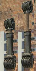
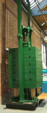
On the Hydraulic multiplier or 'jigger' the pulley system amplified the distance the lifting rope moved for a given movement of the piston, this also meant that the load moved up or down a lot faster than the piston. There were occasions where rapid loading and unloading was an advantage, a good example being a canal, river or sea wharf, and hydraulic hoists and cranes were common in these applications. They were also common on warehouses, usually mounted near the top of the building and providing access to a series of opening ranged up the building for each floor.

The jiggers could be mounted either inside or outside, on free-standing hydraulic cranes they were mounted inside the base of the crane. Where the crane or hoist was mounted on a building they were usually bolted to a wall close by the lift (on the outside of buildings it was typically set vertically into a recess). The example shown is a Jigger of this type. The moveable dock crane, running on rails or small wheels on the quay side, had the jigger mounted inside the base. This had a pulley set at the top but at the bottom there was a set of pulleys on either side as the bottom of the ram was mounted on the frame of the crane. This resulted in a characteristic tapering base to the crane.

Fig ___ Hydraulic Accumulator
Hydraulic accumulator on display at Manchester Science Museum Mains pressure was rather low and was often not available in docks areas so Armstrong invented a water storage tower, called an 'accumulator' in 1850. This consisted of a tall tower containing a water tank with a weighted piston mounted at the top. The water was pumped up the tower using a water wheel or steam driven pump and the weight on the piston provided the pressure and made the practical use of various forms of hydraulic engine possible. These towers were often the tallest structure around, usually brick built and square in form with a slightly bulbous top section reminiscent of a very tall clock tower but without the clock.

Armstrong's firm subsequently became Armstrong Whitworth when they purchased the Whitworth factory in Manchester, and they soon established themselves as the main supplier of hydraulic machinery in Britain. This firm was incidentally also at the forefront of the development of modern artillery.


Fig ___ Warehouse access using Hydraulic jigger
Manchester factory wiuth external hydraulic lift Hydraulic power proved effective and in several cities a system of high pressure hydraulic mains were installed, allowing warehouses and factories to employ jigger-driven hoists without having to build the accumulator and provide an engine to pump it up. The example shown is on a small former garment factory on a side street in Manchester which (I believe) employed the hydraulic mains to power a jigger for their external lifting arrangement (the 'cat head' at the top has since been removed). Built to lift bolts of cloth the doors are only two feet six inches wide.

One odd option that found favour with several smaller firms was to pay for the hydraulic connection and use this to drive a water-wheel driven generator for electricity supply. Apparently this was often a more reliable supply than the available electrical mains.

People had experimented with pneumatic power for some time but there were problems as the technology of the time could not make tight fitting joints. Pneumatic power offers the possibility of using flexible hoses to supply the air to machines and simply venting the air after it has been used. Hydraulics can be connected using flexible hoses but the water inside makes these heavy and for most applications you have to add a second pipe for waste water return.

In 1861 a French engineer by the name of German Sommeiller (1815-1871) developed the first practical pneumatic drill whilst working on a railway tunnel in Europe. This drill was a success and subsequently reciprocating pneumatic drills were widely used in mining and quarrying whilst rotary 'air motors' were developed for use with grinding tools, circular saws and hoisting motors. In Britain compressed air tools were first used underground in about 1849 at a coal mine near Glasgow.

Industries involving inflammable materials such as oil and paper use pneumatic control systems, for example a valve in an oil refinery might be electrically operated but the motor would be controlled by pressure in an air line.


Control Systems & Instrumentation

The word industry appeared about five hundred years ago, although originally it meant something like skill or inventiveness. The modern meaning of the term came with the development of machines (mainly in connection with textiles), and the buildings erected to house them. The word Automation was coined in 1947 by J. Diebold and D. S. Harder, originally it meant a powered, self guiding machine but it is now much more widely applied.
Up to the 1930's most industrial machines and engines were directly operated by people using valves and levers. By the end of the 1930's however remote control systems, often including a degree of automation, were in place. Up to the 1970's most of these control systems relied on 'analogue' functions, a constantly varying electrical voltage, gas pressure or mechanical linkage. Things began to change in the later 1970's as 'integrated circuits' or 'chips' came onto the market and by the end of the 1980's many systems were controlled by a digital computer of some form.

Boilers using higher pressures were prone to exploding, one reason was that no one had worked out a method of gauging the pressure in the boiler. This problem was finally solved in 1849 by the French engineer and instrument maker Eugene Bourdon (1808-1884). Bourdon made a device consisting of a spiral of metal tube with its outer end fixed to the gauge and the inner end connected to the needle. As the pressure in the tube varies the tube tries to straighten out and this moves the needle. The simple and reliable Bourdon tube remains the standard device for local pressure measurement today.

bowden cable

Hydraulic and Pneumatic Propulsion

Pneumatic propulsion has been used in a variety of ways, on the continent and in America there have been numerous compressed air powered locomotives used in mines since the 1870's but the idea did not catch on in Britain. On the surface there have been several attempts to use air pressure to drive railways, the first seems to have been an Irish line in the early 1840's followed by a line from London to Croydon (1846-47) but probably the best known in Britain was the South Devon Railway of the 1840's. The line had a tube running along between the tracks, there was a slot along the top of the tube sealed by a leather flap and pumping stations at intervals extracted the air from the pipe. The coach or wagon had a piston secured beneath the chassis which ran along the tube and air was allowed into one end of the tube to drive the vehicle or vehicles along. The system performed well in service, speeds were high, gradients were coped with easily and of course there was no smoke and little noise. Unfortunately the technology of the time was not up to the job and the leather seal on the pipe gave endless problems. The railway was converted to normal steam hauled operation in 1848 and it soon became apparent that steam engines hauling heavy coaches were having problems on the steep gradients which had posed no problem to the light weight atmospheric vehicles. A variation on this idea was to build a 'tube' type underground railway in which the coaches function as pistons and this was tried in the late nineteenth century but did not catch on.

Hydraulic power has been used on the railways only as a means of coupling a petrol or diesel engine to the locomotive wheels, this is called hydraulic transmission. Hydraulic transmission offers a better power to weight ratio than the more common diesel-electric systems used on locomotives. In the 1950's and 1960's Western Region of British Rail built several classes of diesel-hydraulic locomotive, most of which were successful although their maintenance costs were higher. When using hydraulic transmission there is no risk of electrical sparking so it is safer for use in areas where fire might be a hazard such as oil refineries and is often used for small industrial railway locomotives and lorries.

One quite common machine since the 1970's is the road-rail lorry with diesel hydraulic transmission, which can be used to move railway vehicles as well as for general haulage duties in a refinery or similar establishment.


^
Go to top of page


International Good Guys ~ Making the world a better place since 1971 ~ Site maintained by Disabled Access to Computing
All material Copyright © Mike Smith 2003 unless otherwise credited